OTC Tools 3182 User manual

3182
Digital Battery Load Tester
Test Time: 10 seconds Max Time: 15 seconds
Digital 130 Amp Battery Load/Alternator Tester
Load Switch
OPERATING INSTRUCTIONS

2
When Working on Vehicles
• Always wear approved eye protection.
• Always operate the vehicle in a well-ventilated area. Do not inhale exhaust
gases—they are very poisonous!
• Neversmokeorhaveopenamesnearvehicle.Vaporsfromgasolineandcharging
batteriesarehighlyammableandexplosive.Alwayskeepareextinguishersuitable
forgasoline/electrical/chemicalreshandy.
• Alwayskeepyourself,tools,andtestequipmentawayfromallmovingorhotengine
parts.
• Neverlaytoolsonvehiclebattery.Youmayshorttheterminalstogether,causing
harmtoyourself,thetools,orthebattery.
• Always turn ignition key OFF when connecting or disconnecting electrical
components,unlessotherwiseinstructed.
• Keep away from engine cooling fan. On some vehicles, the fan may start up
unexpectedly.
• Neverleavevehicleunattendedwhilerunningtests.
• AlwaysmakesurethevehicleisinPark(automatictransmission)orNeutral(manual
transmission)andthattheparking brakeisrmlyset.Blockthedrivewheels.
• Alwaysfollowvehiclemanufacturer’swarnings,cautions,andserviceprocedures.
Additional Precautions When Testing
• Discharged batteries will freeze. Store batteries above 32°F (0°C) or maintain
batteriesinachargedcondition.
• TheBatteryLoadTesterbecomeshotduringtest.Allowittocoolbetweentests.
Thedisplaybeginsdimmingwhenthetesterisnotallowedtocool.Repeateduse
intheoverheatedconditioncandamagethetester’selectronics.
• Lead-acid batteries contain sulfuric-acid as the electrolyte.The electrolyte is
extremelycorrosiveandevolvesoxygenandhydrogenduringcharging,whichcan
igniteandcauseanexplosion.Haveventilationandkeepamesandsparksaway
fromchargingbattery.Followthemanufacturer’schargingprocedures.
• Ifelectrolytecontactsskin,immediatelyrinsewithwater.Ifelectrolytecontactseyes,
usheyeswithwaterandcontactphysician.Whenhandlingbatteries,weareye
protection,chemicalresistantglovesandprotectiveclothing.
DISCLAIMER!
Duetoinherentdangersassociatedwithautomotivemaintenanceprocedures,
themanufacturerandallpartiesinvolvedwiththedistributionand/orsaleof
thisequipmentwillnotbeheldliableorresponsible,eitherwhollyorinpart,
foranyinjury,damageorclaimsresultinginitsperformanceortheuseofthe
instructionscontainedinthismanual.
SAFETY PRECAUTIONS

3
Battery Load Tester
The3182DigitalBatteryLoadTesterisahand-held,diagnostictoolusedtotest12V
(volt)and6Vlead-acidtypeautomotivebatteries.A10-secondtestdeterminesthe
conditionofthebattery:Good,WeakorBad.Furthertestingwillidentifypossible
problemsinthechargingandstartingsystems.Testscanbeperformedonfully
orpartiallychargedbatteriesbyinspectingtheelectrolyteoropen-circuitvoltage
andadjustingthevaluesfortemperaturesotherthan70°F(21.1°C).
• Iftheelectrolyteisaccessible,measureitsspecicgravitywithahydrometer.
Thespecicgravityreadingshouldbe1.225orhigherat70°F(21.1°C).For
every10°F(5.6°C)above/below70°F(21.1°C),add/subtract0.004to/fromthe
reading.
• Theopen-circuitvoltageshouldbeatleast12.45Vat70°F(21.1°C).
TheBatteryLoadTestercontainsafour-characterLCD(liquidcrystaldisplay)to
displaybatteryvoltage,aswitchtoapplythetestloadandaredLEDthatisused
toindicatetheconditionofthealternator.Thetesterispoweredbythebattery
undertest.
CAUTION!
• Test procedures and information provided in this manual are intended
as general guidelines for engine tune-up and adjustments only. Consult
the applicable vehicle service manuals for all specic tests.
• Before testing, read and follow all safety precautions.
• Do not activate and hold the load switch for more than 15 seconds.
This will overload the tester resulting in damage and void the warranty.
Test Preparation
Multi-Battery Systems
Inallmultiplebatterysystems,allbatteriesmustbetestedseparately.Batteries
may be connected in series, parallel or a combination of both. Only batteries
connectedinseriesmayremainconnectedduringtest.See Figure 1.
Forseriesconnections,allbatteriesareconnectedfromthenegative(-)terminal
ofonebattery,tothepositive(+)terminaloftheother.Onlythenegativeterminal
oftherstbatteryandthepositiveterminalofthelastbatteryaretobeconnected
tothevehicle.Anynumberofbatteriesmaybeconnectedinaseries.However,
each battery must be tested separately.
Forallotherconnections(paralleloracombinationofparallelandseries),the
batteries mustbedisconnectedandelectricallyisolatedfromeachother.
TO VEHICLE POWER TO VEHICLE GROUND
POS NEG POS NEG POS NEG
Figure 1 Multi-Battery Test Conguration
4
Vehicle Battery
1.TurnignitionkeyOFF;notintheACCESSORIES
position (Figure 2).EngineneedstobeOFFand
all electrical loads must be removed from the
batteryforpropertesting.Ifloadsstillexist,refer
tothevehiclesoperatorandservicemanual.
2.Ifbatteryisbeingcharged,thenstop,turncharger
OFFanddisconnectclampsorleads.Thebattery
cannotbetestedwhilebeingcharged.
3.Theconnectionsmustbecleanandmustmake
goodcontacttoachievecorrecttestresults.
4.On side-post type batteries, install terminal stud adapters. These are not
included,butareavailableatmostautomotivepartsstores.
Battery Temperature
The most accurate test results will be obtained when battery temperature is
at approximately 70°F (21.1°C). If testing battery between 70°F (21.1°C) and
40°F(4.4°C),add0.1voltforevery10°F(5.6°C)below70°F.Iftestingabattery
between70°F(21.1°C)and100°F(37.8°C),subtract0.1Vforevery10°F(5.6°C)
above70°F(21.1°C).
Load Test
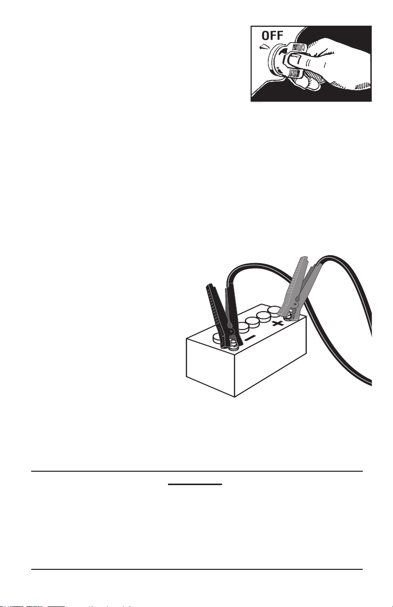
1.Connect the tester’s Black
clamptothenegative(-)battery
terminal and the Red clamp to
thepositive(+)batteryterminal
(Figure 3).Makesurebothjaws
makegoodcontact.Ifrequired,
rock clamps back and forth to
improve connection.
2.TheLCDdisplaywillturnonand
displaythebatteryvoltage.Thebatterymustbeatleast75%chargedbefore
conductingtheLoadTest.At70°F(21.1°C),thevoltageshouldbeatleast12.45V
(or6.23Vfora6Vbattery).Remembertoadjustvoltagefortemperaturesother
than70°F(21.1°C).
CAUTION!
• The Battery Load Tester becomes hot when applying the load.
Allow tester to cool between discharges; about 2 minutes. In warm
temperatures, allow more time to cool. If overheating occurs, the LCD
might temporarily become dim. After cooling down, the tester’s LCD
will return to normal.
• Do not activate and hold the load switch for more than 15 seconds.
This will overload the tester resulting in damage and void the warranty.
Figure 2 Engine OFF
Figure 3 Battery Connections
5
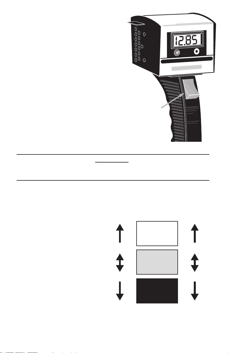
3.PressandholdtheLOAD SWITCHfor
10seconds.RefertoFigure 4.
4.Observe the voltage on the LCD and
note the value. Release the LOAD
SWITCHimmediatelyafterreadingthe
display.
5.Disconnect the Red clamp from the
batteryandthentheBlackclamp.
6.Figure 5showstherangefora500CCA
(Cold-CrankingAmperage) battery
tested at 70°F (21.1°C). For batteries
ratedatotherCCAvalues,subtract0.1V
forevery100CCAbelow500CCAfrom
thevaluesshowninFigure 5.Add0.1V
forevery100CCAabove500CCA.
IfthevoltageisintheWEAKregion,then
thebatteryisprobablydischargedand
needstobechargedbeforetesting.
• Disconnecttesterandchargebattery;
followbatterychargermanufacturer’s
instructionsforchargingprocedures.
WARNING!
Charging a battery with a bad cell may cause severe personal injury and
damage to vehicle and/or equipment.
• Disconnectcharger,reconnecttesterandretest.Ifthevoltageremainslow,
thenthebatteryisnotacceptingachargeandshouldbereplaced.
Test Results
GOOD - means the battery is in
good condition and should start
the vehicle in any environment.
WEAK - Indicates the battery is
dischargedandrequirescharging.
Chargebatteryandthenretest.
• IfbatterytestsWEAKasecond
time,thiscouldindicateoneor
more cells are bad and battery
mustbereplaced.
• If battery reads GOOD, the
battery was not suciently
chargedduringthersttest.
BAD - Indicates the battery is
deeply discharged and requires
acompletechargeorthebattery
isbadandrequiresreplacement.Checkthefollowing(onpage6)andretest.
Test Time: 10 seconds Max Time: 15 seconds
Digital 130 Amp Battery Load/Alternator Tester
Load Switch
Load Switch
Figure 4 Load Switch and Display
Figure 5 500 CCA Test Results at 70°F (21.1°C)
GOOD
WEAK
BAD
10.00V
6.10V 3.05V
5.00V
12V Battery 6V Battery
Table of contents
Other OTC Tools Test Equipment manuals

Popular Test Equipment manuals by other brands


Redtech
Redtech TRAILERteck T05 user manual

Venmar
Venmar AVS Constructo 1.0 HRV user guide

Test Instrument Solutions
Test Instrument Solutions SafetyPAT operating manual

Hanna Instruments
Hanna Instruments HI 38078 instruction manual

Kistler
Kistler 5495C Series instruction manual

Waygate Technologies
Waygate Technologies DM5E Basic quick start guide

StoneL
StoneL DeviceNet CK464002A manual

Seica
Seica RAPID 220 Site preparation guide

Kingfisher
Kingfisher KI7400 Series Training manual

Kurth Electronic
Kurth Electronic CCTS-03 operating manual

SMART
SMART KANAAD SBT XTREME 3G Series user manual

Agilent Technologies
Agilent Technologies BERT Serial Getting started