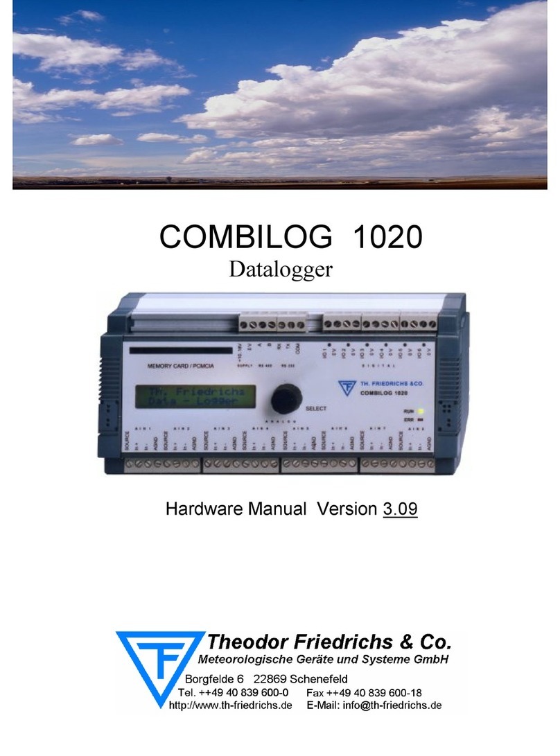
OTR D3200PRO User manual

O.T.R. s.r.l. Via Btg. Susa 36 29122 Piacenza +39 0523 594290
www.otr-geo.it info@otr-geo.it P.IVA 00894610153
USE AND MAINTENANCE MANUAL
Datalogger D3200PRO
PAGINA 01
Numero 019b
Rev. 02 del 07/07/2022

O.T.R. s.r.l. Via Btg. Susa 36 29122 Piacenza +39 0523 594290
www.otr-geo.it info@otr-geo.it P.IVA 00894610153
USE AND MAINTENANCE MANUAL
O.T.R. s.r.l. Via Btg. Susa 36 29122 Piacenza +39 0523 594290
www.otr-geo.it info@otr-geo.it P.IVA 00894610153
PAGINA 02
STRUMENTI E MISURE GEOTECNICHE
E STRUTTURALI
INDEX
Warnings
Applications
Model and ID
Sensor connection
Sensor properties
Calculation of battery life
Battery datalogger telephone module
Software conventions
Troubleshooting
GSM and Solar Panel
Installation and maintenance
Technical Features
Quick Installation
Using main controls
5
6
7
8
11
15
16
17
18
19
21
23
24
35
PAGINA 03DATALOGGER D3200PRO
Numero 019b
Rev. 02 del 07/07/2022
Numero 019b
Rev. 02 del 07/07/2022

O.T.R. s.r.l. Via Btg. Susa 36 29122 Piacenza +39 0523 594290
www.otr-geo.it info@otr-geo.it P.IVA 00894610153
USE AND MAINTENANCE MANUAL
O.T.R. s.r.l. Via Btg. Susa 36 29122 Piacenza +39 0523 594290
www.otr-geo.it info@otr-geo.it P.IVA 00894610153
PAGINA 04
Datalogger D3200PRO WARNINGS
!
!
!
!
The instrument should be used only for the application for which it was
built and designed, OTR disclaims any responsibility for improper use
of the instrumentation.
Use only the power supply and cables provided;
Do not use the datalogger in the presence of potentially explosive
gases;
Do not connect the datalogger to instrumentation placed in waters
where electrical leakage is occurring;
• Do not open the instrument: contact the manufacturer for any repairs;
• Keep out of the reach of children;
• Do not make instrument connections with wet or damp hands;
• When charging, do not connect the datalogger to the probe or personal
computer via USB;
• Clean the instrument and its cable with alcohol or water; Do not use
acetone or aggressive liquids for plastics or labels;
Furthermore
Use protective gloves when using the measuring cable. Avoid handling
the cable quickly without gloves.
PAGINA 05
DATALOGGER D3200PRO
Numero 019b
Rev. 02 del 07/07/2022
Numero 019b
Rev. 02 del 07/07/2022

O.T.R. s.r.l. Via Btg. Susa 36 29122 Piacenza +39 0523 594290
www.otr-geo.it info@otr-geo.it P.IVA 00894610153
USE AND MAINTENANCE MANUAL
O.T.R. s.r.l. Via Btg. Susa 36 29122 Piacenza +39 0523 594290
www.otr-geo.it info@otr-geo.it P.IVA 00894610153
PAGE 06 PAGE 07
The 32 channel Dataloggers in the D3200PRO series are suitable for monitoring in
Geotechnical, Structural and Environmental fields with mV or mA output sensors.
The following instruments can be acquired:
• Electric piezometers
• Surface clinometers
• Crackmeters and joint gauges
• Temperature sensors
• Conductivity meters.
Application Model and Identification
Each Datalogger has nameplates bearing:
• Serial number with associated calibration report;
• Model indication;
• Indication of power supply;
• Input/Output
Technical Specification
0-2V 4-20 mA
+15V , 2.048 Vref
6V dc
Inputs
Outputs
Power Supply
DATALOGGER D3200PRO
Numero 019b
Rev. 02 del 07/07/2022
Numero 019b
Rev. 02 del 07/07/2022

O.T.R. s.r.l. Via Btg. Susa 36 29122 Piacenza +39 0523 594290
www.otr-geo.it info@otr-geo.it P.IVA 00894610153
USE AND MAINTENANCE MANUAL
O.T.R. s.r.l. Via Btg. Susa 36 29122 Piacenza +39 0523 594290
www.otr-geo.it info@otr-geo.it P.IVA 00894610153
PAGE 08 PAGE 09
Connecting sensors
Vibrating rope version
Refer to the figure contained on page 11 to connect the vibrating rope sensors.
The figure represents the datalogger’s multiplexer board.
Before connecting the sensors to the datalogger, it is a good idea to previously
check that they are working and properly wired upstream. For this it would be
useful to have a handy hand reader with you to check the transducers before
final wiring.
Connect the first vibrating cord sensor into the white-colored quadruple
terminal indicated by CH0. The first (from the top) screw terminal should be
connected to the positive pole of the sensor coil (COIL+) normally indicated with
the color RED. The second terminal should be connected to the negative (COIL -)
pole of the coil normally indicated with the color BLACK.
The OG3200PRO datalogger is capable of reading sensors with resonance
frequency above 501 Hz. The universal sweep requires no software setting, and
the data output is directly in Hz or Hz squared. For use with self-oscillating or
different frequency sensors, consult OTR directly.
Terminals 3 and 4 should be connected to the thermistor associated with the
sensor (normally color 3 to GREEN and 4 to WHITE).
The standard of thermistors read by the OG3200PRO datalogger is NTC 3Kohm.
If the thermistor is not of this type wire it and then proceed with the software
to read and record in Ohms. From these derive the data in degrees using the
corresponding formulas for the NTC or PTC sensors used.
Repeat the operation with the next sensors, taking care to connect the quad
clamps sequentially one after the other (if an empty quad terminal is left
between two wired with sensors it too will be unnecessarily read and recorded).
Check that the screw terminals are tight and that the wires are not shorted.
After all sensors are wired, proceed with a continuous measurement to check
that the whole operation was successful.
DATALOGGER D3200PRO
mV or 4-20mA version
To connect sensors with mV or 4-20 mA output, refer to the figure contained on
page 24. The figure represents the datalogger’s multiplexer board.
Before connecting the sensors to the datalogger, it is a good idea to previously
check that they are working and properly wired upstream. For this it would be
useful to have a handy hand reader with you to check the transducers before
final wiring.
To connect sensors with mV output, locate the sensor power cable and connect
it to the first slot (from the top) of the quad terminal. Wire the sensor ground
(GND) wire to the second slot and finally the signal wire to the third slot. If the
sensor is biaxial (ex: inclinometer) connect its second output to the third slot of
the next quad terminal, taking care to return the power supply to the latter (so a
loop must be made between the first slot of the quad terminal ex: X and the first
slot of the next quad terminal ex: Y). In this way, the biaxial sensor is properly
connected and powered. Check that the black 4-20 mA selection jumper is
disconnected. The voltages read by the datalogger range from - 4,000 to +
4,000 Vdc. Higher or lower values will be reported as Full Scale and will not be
read correctly.
To connect sensors with two-wire 4-20 mA output, locate the power cable
(LOOP+) and the signal cable (LOOP-). Wire the LOOP+ cable to the first slot of
the quad terminal and the LOOP- cable to the third. Check that the black 4-20
mA selection jumper is connected.
For connecting sensors with 4-20 mA three-wire output, locate the power cable
(LOOP+), signal cable (LOOP-) and ground cable (GND). Wire the LOOP+ cable
to the first slot of the quad terminal, the GND cable to the second and finally
the LOOP- cable to the third. Check that the black 4-20 mA selection jumper is
connected.
Check that the screw terminals are tight and that the wires are not shorted.
After all the sensors have been wired, proceed with a continuous measurement
to check that the whole operation was successful.
For sensors with mV output, it is essential that the 100-ohm load resistor be
disconnected by removing the black jumper. Incorrect use of this jumper results
in unexpected low signal values
For sensors with mA output, it is essential that the 100 Ohm load resistor is
connected by inserting the corresponding black jumper. Incorrect use of this
jumper results in full-scale values. Correct use gives values of 0.400 volts
for 4 mA and 2,000 volts for 20 mA found between slot 2 and slot 3 of the
corresponding quad terminal.
The datalogger is capable in all cases of reading currents between - 40,000 and
+ 40,000 mA, and the instructions for 4-20 mA sensors also apply to 0-20 mA
sensors.
Numero 019b
Rev. 02 del 07/07/2022
Numero 019b
Rev. 02 del 07/07/2022

O.T.R. s.r.l. Via Btg. Susa 36 29122 Piacenza +39 0523 594290
www.otr-geo.it info@otr-geo.it P.IVA 00894610153
USE AND MAINTENANCE MANUAL
O.T.R. s.r.l. Via Btg. Susa 36 29122 Piacenza +39 0523 594290
www.otr-geo.it info@otr-geo.it P.IVA 00894610153
PAGE 10 PAGE 11
The screen allows access to the datalogger’s clock parameters and acquisition
enablement.
The Read Date and Write Date buttons allow the user to update the date entered
in the datalogger on the screen and to edit the date within it if necessary,
respectively. Editing is done by selecting the relevant data boxes and then
pressing the write button.
At the bottom is a check that indicates whether the datalogger is enabled for
conversion or not. If the check is selected the datalogger acquires at each
conversion time starting when the program is closed or the cable is disconnected.
If the check is not selected the datalogger is in stand-by and does not acquire. Its
consumption in this state is about 200 µA.
Data Mood
With these options you set the acquisition times of the datalogger. Times
below one minute cannot be set, and if channel scanning exceeds this time it is
automatically delayed. For the version with GSM the acquisition times cannot be
less than 10 minutes.
Also in the screen is the setting of pre-start times that control how long the
datalogger waits before taking a sensor reading. For the vibrating string version,
the preignition time is meaningless.
Timers
In this screen you can manage the quantity of channels connected to the
datalogger. The two buttons Read and Write are used to control these parameters.
For each MUX, 0 to 16 active channels can be set. When changing these values,
the software asks for confirmation because the memory is reset if the channel
configuration is changed. This is necessary for internal dislocation of data in
the datalogger. Therefore, before adding or removing channels remember to
download the data.
If the value of channels is set to 0 the corresponding MUX is ignored and the
memory possibility is increased as follows:
1 MUX 4000 data
2 MUX 2000 data
3 or 4 MUX 1000 data
The Clear Data Memory button allows the datalogger’s memory buffer to be
completely cleared.
The Reset Datalogger Completely button, on the other hand, allows the datalogger
to be returned to its first power-up state. However, this operation results in the
loss of all data and also all configurations and should only be used if strictly
necessary.
Channel Managing
mV/mA version
The properties of the various sensors are accessed with the appropriate button.
Each sensor is identified by a number ranging from 0 to 15 and its MUX number
ranging from 0 to 3.
For each sensor, a name and four numeric configuration parameters can be set,
allowing for a given output in any physical format.
The reference formula is as follows:
( )
Z_FZ_F-F_F
Z_V-F_V
Z_V-In
Out +
×
=
Out = output value
In = input value in tenths of millivolts
Z_V = zero in tenths of millivolts
F_V = Full scale in tenths of millivolts
F_F = Full scale in physical units
Z_F = Zero physical units
Actually, the formula is very simple and does not require any special calculations.
It is sufficient to take two points on the characteristic curve of the sensor and
proceed as follows:
Properties of sensors
PAGINA 11
PAGINA 10
Wiring
Numero 019b
Rev. 02 del 07/07/2022
Numero 019b
Rev. 02 del 07/07/2022
DATALOGGER D3200PRO

O.T.R. s.r.l. Via Btg. Susa 36 29122 Piacenza +39 0523 594290
www.otr-geo.it info@otr-geo.it P.IVA 00894610153
USE AND MAINTENANCE MANUAL
O.T.R. s.r.l. Via Btg. Susa 36 29122 Piacenza +39 0523 594290
www.otr-geo.it info@otr-geo.it P.IVA 00894610153
PAGE 12 PAGE 13
The transducer has an output of 4 mA at 0 mm and 20 mA at 100 mm therefore:
At 4 mA the Zero value in tenths of millivolts corresponds to 4000 and at 20 mA
the Full scale value in tenths of millivolts corresponds to 20000.
The four values are then:
Zero_Volts = 4000
Fs_Volts = 20000
Zero_Physical = 0
Fs_Physical = 100
The output is thus in mm. If you want to have it in cm simply put
Fs_Physical = 10
4-20 mA potentiometric
transducer -100 mm
Inclinometer with output +/- 2 volts
around 2.5 volts and FS=+/- 30°
The transducer has a nominal zero at 2.5 V corresponding to 25000 tenths of a
millivolt.
Zero_Volt = 25000
The value indicated by the transducer at this position is nominally 0°
Zero_Physical = 0
At full scale, the transducer has an output of 4.5 volts corresponding to 45000
tenths of a millivolt.
Fs_Volt=45000
At this position the inclination is equal to +30°
Fs_Physical = 30
Here are found the four parameters for having an output in degrees (of course the
software also leaves a reasonable number of floating-point digits).
Piezometric transducer
4-20mA 20m water
Il trasduttore ha un’uscita di 4 mA a 0 m e quindi di 20 mA a 20 m:
A 4 mA il valore di zero in decimi di millivolt corrisponde a 4000 e a 20 mA il valore
di fondo scala in decimi di millivolt corrisponde a 20000.
I quattro valori sono quindi:
Zero_Volts = 4000
Fs_Volts = 20000
Zero_Fisico = 0
Fs_Fisico = 20
L’uscita è quindi in m. Se si desidera averla in cm basta mettere
Fs_Fisico = 2000
Barometer with output in volts
The transducer in example has an output of 0.1V at 15KPa and 2.35V at 115KPa:
At 15Kpa the value in tenths of mV is therefore 1000 while at 115Kpa it is 23500.
The four values are therefore:
Zero_Volt = 1000
Fs_Volt = 23500
Zero_Physical = 15
Fs_Physical = 115
The output is thus in KPa.
Example of data file
The data downloaded from the datalogger are easy to interpret and collect all
information regarding the sensors and their properties.
If immediate visualization of the data is desired, simply select the ‘Create Table ‘
option before downloading.
An example file of the ASCII file created is shown.
The file shows the date of download the various sensor information and the data
neatly separated by commas.
DATALOGGER D3200PRO
Numero 019b
Rev. 02 del 07/07/2022
Numero 019b
Rev. 02 del 07/07/2022

O.T.R. s.r.l. Via Btg. Susa 36 29122 Piacenza +39 0523 594290
www.otr-geo.it info@otr-geo.it P.IVA 00894610153
USE AND MAINTENANCE MANUAL
O.T.R. s.r.l. Via Btg. Susa 36 29122 Piacenza +39 0523 594290
www.otr-geo.it info@otr-geo.it P.IVA 00894610153
PAGE 14 PAGINA 15
Importing data into Microsoft Excel
Open Microsoft Excel.
Open the file created by D3200PRO as a text file (.TXT).
Start importing from the row where the data begins.
Select the data as comma delimited.
Finish the import.
DATA ACQ.: 06/01/2005 17.55.37,Numero Canali Attivi: 3 ,Numero Dati per
Canale: 234
CANALE: 00 Y 25000 45000 0 2000
CANALE: 01 X 25000 45000 0 2000
CANALE: 02 T 5000 10000 0 50
05/01/2005 14.01.26 ,-710.8 ,228.8 ,17.96
05/01/2005 14.03.48 ,-711.8 ,228.4 ,17.56
05/01/2005 14.05.48 ,-712.0 ,228.4 ,17.26
05/01/2005 14.07.48 ,-711.4 ,229.4 ,16.94
05/01/2005 14.09.48 ,-711.2 ,229.4 ,16.72
05/01/2005 14.11.48 ,-711.0 ,229.6 ,16.48
05/01/2005 14.13.48 ,-710.8 ,230.0 ,16.26
05/01/2005 14.15.48 ,-711.6 ,229.4 ,16.04
05/01/2005 14.17.48 ,-711.0 ,229.8 ,15.84
05/01/2005 14.19.48 ,-712.0 ,229.6 ,15.64
05/01/2005 14.21.48 ,-711.8 ,229.8 ,15.48
05/01/2005 14.23.48 ,-711.6 ,230.0 ,15.32
05/01/2005 14.25.48 ,-711.2 ,230.4 ,15.24
05/01/2005 14.27.48 ,-711.8 ,230.0 ,15.12
05/01/2005 14.29.48 ,-711.4 ,230.6 ,15.04
05/01/2005 14.31.48 ,-712.0 ,230.2 ,14.92
05/01/2005 14.33.48 ,-711.6 ,230.8 ,14.86
05/01/2005 14.35.48 ,-711.4 ,230.8 ,14.78
05/01/2005 14.37.48 ,-712.0 ,230.4 ,14.68
05/01/2005 14.39.48 ,-711.8 ,231.0 ,14.6
05/01/2005 14.41.48 ,-712.2 ,230.4 ,14.5
05/01/2005 14.43.48 ,-711.8 ,231.2 ,14.44
05/01/2005 14.45.48 ,-712.2 ,231.0 ,14.38
05/01/2005 14.47.48 ,-712.2 ,230.8 ,14.3
05/01/2005 14.49.48 ,-712.0 ,231.4 ,14.24
05/01/2005 14.51.48 ,-712.2 ,230.8 ,14.16
05/01/2005 14.53.48 ,-711.4 ,231.4 ,14.08
05/01/2005 14.55.48 ,-712.2 ,230.8 ,14.0
05/01/2005 14.57.48 ,-712.4 ,231.0 ,13.92
05/01/2005 14.59.48 ,-712.0 ,230.8 ,13.88
05/01/2005 15.01.48 ,-712.4 ,231.0 ,13.8
05/01/2005 15.03.48 ,-712.2 ,231.0 ,13.76
Calculation of Battery Autonomy
Il consumo in stand by del datalogger è di circa 200 µA.
Il consumo in pieno utilizzo (durante la misura) si aggira intorno ai
100 mA.
Approssimatamente il tempo di acquisizione per canale può essere
considerato 4 sec a cui va sommato un tempo di 10 sec ad ogni
accensione.
Partendo da questi due dati è possibili con semplici calcoli calcolare
in modo ragionevole la durata prevista delle batterie.
Esempio di calcolo:
Condizioni: Batterie Torcia 15 A/h, 4 acquisizioni al giorno, 16 sensori
collegati
Daily consumption:
+
×
××+× 3600
10
3600
416
mA100424uA200
giornoalA0.00130A0.0082A0.0048 =+
Duration =
0130.0
15
=1154 Days
Even dividing the result by a safety factor of 3 gives a range of about 1
year.
Conditions: 15 A/h ashlight batteries, 96 acquisitions per day, 2 sen-
sors connected
Daily consumption:
+
×
××+× 3600
10
3600
42
mA1009624uA200
0.0048 A + 0.048 = 0.0528 Daily
Duration =
0528.0
15
=284 Days
µA 24 mA 16 10
15
µA 24 96 mA 10
15
Even dividing the result by a safety factor of 3 gives a range of about 3 months.
DATALOGGER D3200PRO
The standby consumption of the data logger is about 200 µA.
The consumption in full use (during measurement) is around 100 mA.
Approximately the acquisition time per channel can be considered 4 sec to which
should be added a time of 10 sec at each power-up.
Starting from these two data, it is possible with simple calculations to reasonably
calculate the expected battery life.
Example calculation:
Conditions: 15 A/h flashlight batteries, 4 acquisitions per day, 16 sensors
connected
Numero 019b
Rev. 02 del 07/07/2022
Numero 019b
Rev. 02 del 07/07/2022

O.T.R. s.r.l. Via Btg. Susa 36 29122 Piacenza +39 0523 594290
www.otr-geo.it info@otr-geo.it P.IVA 00894610153
USE AND MAINTENANCE MANUAL
O.T.R. s.r.l. Via Btg. Susa 36 29122 Piacenza +39 0523 594290
www.otr-geo.it info@otr-geo.it P.IVA 00894610153
PAGE 16 PAGE 17
Battery Datalogger phone module
If the datalogger supplied has the telephone module, a solar panel or battery
charger is also provided. The phone consumes approximately 30 mA and the
battery/panel system is sized according to the area and conditions of use.
If sizing is correct and external factors (snow on the panel, leaves etc. etc.) do not
intervene, however, the life of rechargeable batteries should be considered to be
about a couple of years due to aging factors and loss of storage capacity.
Where possible and reasonably safe, it is advisable to use solar panels and
rechargeable batteries that isolate the datalogger in every way from unwanted
external disturbances.
Replacing Flashlight Batteries
Use model LR20 SIZE D alkaline flashlight batteries. Be careful that the batteries
do not release acid.
Battery Replacement
Replacement of Batteries with
sealed lead-acid
Use 6Vdc 12Ah sealed lead acid batteries after proper and sufficient charging.
Software Conventions
Per il corretto utilizzo del software OG3200PRO devono essere controllate alcuni
parametri di Windows nel pannello di controllo.
Entrare in start e successivamente in opzioni internazionali e numeri.
Il simbolo di separazione decimale deve essere “ . ” ed il simbolo di raggruppamento
cifre “ ’ ”.
Se queste convenzioni non vengono rispettate il programma non riceve i dati dal
datalogger in modo corretto.
Serial connection and USB adapters
The OG3200PRO datalogger uses a standard 3-wire + 1-wire RS232 serial
connection for awakening from the standby state. It is therefore necessary to have
a full serial. The OG3200PRO version that is not GSM-ready has a 57600,n,8,1
protocol the GSM-ready version 9600,n,8,1.
Common USB/Serial adapters are perfect for connection with the OG3200PRO
datalogger. In case of using adapter, the supplied connection cable is not necessary
either. The connection can be made in a direct way.
DATALOGGER D3200PRO
Numero 019b
Rev. 02 del 07/07/2022
Numero 019b
Rev. 02 del 07/07/2022

O.T.R. s.r.l. Via Btg. Susa 36 29122 Piacenza +39 0523 594290
www.otr-geo.it info@otr-geo.it P.IVA 00894610153
USE AND MAINTENANCE MANUAL
O.T.R. s.r.l. Via Btg. Susa 36 29122 Piacenza +39 0523 594290
www.otr-geo.it info@otr-geo.it P.IVA 00894610153
PAGE 18 PAGE 19
Troubleshooting
• Check that the selected serial is correct
• Check that the cable is properly connected
• Check the integrity of the connecting cable
• Check the status of the batteries
• Remember that the GSM version needs the appropriate check selected in the
initial window.
Datalogger does not connect
• Check that the conversion enable check is active
• Check that there is still free memory
• Check that the datalogger’s internal date and time are correct.
Datalogger does not record
measurements
• Check for correct wiring
• Check for the presence of moisture
• Check international settings and setting of sensor parameters
• Check the status of the batteries
• Remember that for biaxial sensors it is necessary to report + power on each
quad terminal used for them.
The measurements do not seem
correct
• Check that the PC in use has no other programs running.
Downloading data is difficult and
time-consuming
GSM and Solar Panel
To connect to the GSM modem, simply use the cable supplied with the phone and
plug it into the appropriate connector.
Remember that for local connection it is necessary to disconnect the GSM serial
socket in order not to have two devices on the same line.
The OG3200PRO with the GSM phone works at 9600 baud so for local connection
you must use the ‘GSM Version’ option in the initial screen of the software.
Upon connection the GSM modem will start flashing in the presence of the field.
Remember to use prepaid or non-prepaid cards enabled for incoming traffic.
It is necessary that the card inserted in the GSM is unlocked i.e. with PIN request
disabled.
GSM modem connection
Also supplied with the GSM version is a 10W solar panel, a 12/18 Vin, 7.2 Vout
panel charger, a 6V-12 A/h sealed lead-acid battery with very high range.
Do not use the battery charger with panels with power higher than 15W.
Do not use different panel chargers (standards are 12 Vdc Out).
Caution in full charge the charger radiator can reach up to 70°C.
Using the solar panel
DATALOGGER D3200PRO
Numero 019b
Rev. 02 del 07/07/2022
Numero 019b
Rev. 02 del 07/07/2022

O.T.R. s.r.l. Via Btg. Susa 36 29122 Piacenza +39 0523 594290
www.otr-geo.it info@otr-geo.it P.IVA 00894610153
USE AND MAINTENANCE MANUAL
O.T.R. s.r.l. Via Btg. Susa 36 29122 Piacenza +39 0523 594290
www.otr-geo.it info@otr-geo.it P.IVA 00894610153
PAGE 20 PAGE 21
• Use the charge module in the following way:
Connecting the solar panel and
panel charger
VDAT:
Positive datalogger power supply (red wire)
GND:
Negative datalogger power supply (black cable)
VPAN:
Positive panel voltage (color depends on panel supplied)
GND:
Negative panel voltage (color depends on panel supplied)
VBAT:
Positive battery voltage (red wire)
GND:
Negative battery voltage (black cable)
It is also possible to plug into the VPAN/GND input the output of a stabilized
12/18 Vdc 1 Amp power supply to put the battery on charge before installation or
to power the datalogger with mains voltage.
NB: In case of mains power supply, it is necessary to make sure that the power
supply is professional and adequate, protected from surges, with surge filters.
Otherwise sudden surges and disturbances from the mains could make it
impossible for the device to work properly.
It is also recommended not to carry out programming with the datalogger under
charge with a mains power supply and a PC also connected to the mains.
If the datalogger does not have sealed lead-acid batteries (flashlight battery
version without GSM), do not try to recharge the batteries.
Installation and Maintenance
The housing supplied with the datalogger has a protection rating of IP65 or IP66.
The housing must be properly closed and each of its cable glands sealed with
a piece of cable if not in use. If operating under special conditions (particularly
humid environments, freeze-thaw cycles), additional protection is recommended
to avoid condensation problems inside the housing.
Installing
Maintenance of the data logger is limited to a few simple rules:
- Check the condition of the battery at each data dump
- Check the internal condition of the box to prevent condensation moisture
problems.
If not in use for several months, the following rules should be followed to
safeguard the internal buffer battery:
- Recharge or replace the external batteries after the last measurement campaign.
- Store the datalogger with the external batteries connected in the stand-by
condition.
Under this condition, the life of the buffer battery is unlimited.
The life of the internal buffer battery is unlimited under normal use but becomes
6-12 months under complete non-use. Therefore, it is recommended to store the
datalogger in stand-by condition to avoid unnecessary discharge of the buffer
battery.
Manteinence
DATALOGGER D3200PRO
Numero 019b
Rev. 02 del 07/07/2022
Numero 019b
Rev. 02 del 07/07/2022

O.T.R. s.r.l. Via Btg. Susa 36 29122 Piacenza +39 0523 594290
www.otr-geo.it info@otr-geo.it P.IVA 00894610153
USE AND MAINTENANCE MANUAL
O.T.R. s.r.l. Via Btg. Susa 36 29122 Piacenza +39 0523 594290
www.otr-geo.it info@otr-geo.it P.IVA 00894610153
PAGINA 22 PAGE 23
If you feel that you have not followed the previously described steps correctly
after a long period of inactivity of the datalogger, it is advisable to replace the
internal battery. The battery is lithium and readily available (PANASONIC model
CR2330 or equivalent).
The operation LED of the datalogger to indicate the complete reset of the
equipment flashes 4 times at the first power on.
This operation implies the loss of data and configuration of the datalogger.
After disassembling the plate that holds the datalogger you will easily find the
battery holder. Replace the buffer battery with an equivalent one taking care not
to short-circuit it in disassembly and reassembly. Take care to mount the battery
with the correct polarity indicated.
The operation described above should be done by disconnecting the main
batteries first.
When replacing the buffer battery with the external batteries connected, it is
necessary to press with a pencil the yellow metal button “RESET” located on the
rear board of the datalogger.
Internal Buffer Battery Replacement Technical Features
Rabbit 3000
Microprocessor
Up to 64 channels in volts or 4-20 mA individually selectable for the volts or
mA version and 64 vibrating chord channels with associated thermistors for the
vibrating chord version.
Number of measurable channels
40000 measurement points on +/-4Vdc or +/-2Vdc and +/- 1 Vdc or +/- 4.5Vdc
on request. 0.01 to 0.5 Hz for vibrating string version.
Resolution
+15 volts or +12 volts upon request.
5.5-V sweep from 500 to 6000 Hz for the vibrating string version.
Sensor power supply
<15 ppm/°C
Temperature stability
Da –20°C +55°C
Operating temperature
256 kB buffered RAM and 256 kb flash memory
Memory
Approximately 200uA in standby and 100mA in full operation
Consumption
Sequential relays
MUX
DATALOGGER D3200PRO
Numero 019b
Rev. 02 del 07/07/2022
Numero 019b
Rev. 02 del 07/07/2022

O.T.R. s.r.l. Via Btg. Susa 36 29122 Piacenza +39 0523 594290
www.otr-geo.it info@otr-geo.it P.IVA 00894610153
USE AND MAINTENANCE MANUAL
O.T.R. s.r.l. Via Btg. Susa 36 29122 Piacenza +39 0523 594290
www.otr-geo.it info@otr-geo.it P.IVA 00894610153
PAGE 24 PAGE 25
Quick Installation
To install the software:
1. Insert the fuse into the fuse holder on the red cable connecting the
battery to the charge controller.
2. Connect the battery. The red cable should be connected to the red
terminal of the battery, and the black cable to the black terminal.
3. If the datalogger LED lights up, wait for it to turn off. As long as the
datalogger LED remains lit, the datalogger cannot be made to communicate with
the computer.
4. Plug the USB-Serial adapter into the PC.
5. Wait for the device drivers to install. The adapter requires the installation
of two drivers. If the drivers do not install automatically, proceed as follows:
Find the adapter in Device Manager:
DATALOGGER D3200PRO
Right-click and select Driver Software Update:
Numero 019b
Rev. 02 del 07/07/2022
Numero 019b
Rev. 02 del 07/07/2022

O.T.R. s.r.l. Via Btg. Susa 36 29122 Piacenza +39 0523 594290
www.otr-geo.it info@otr-geo.it P.IVA 00894610153
USE AND MAINTENANCE MANUAL
O.T.R. s.r.l. Via Btg. Susa 36 29122 Piacenza +39 0523 594290
www.otr-geo.it info@otr-geo.it P.IVA 00894610153
PAGE 26 DATALOGGER D800-D1600-D3200 PAGE 27
Look for the driver in the computer:
Find the USB-232 INSTALL folder contained on the CD provided by OTR and then
click Continue:
DATALOGGER D3200PRO
Find the USB-232 INSTALL folder contained on the CD provided by OTR and then
click Continue:
Right-click and choose “Update Driver Software.”
Numero 019b
Rev. 02 del 07/07/2022
Numero 019b
Rev. 02 del 07/07/2022

O.T.R. s.r.l. Via Btg. Susa 36 29122 Piacenza +39 0523 594290
www.otr-geo.it info@otr-geo.it P.IVA 00894610153
USE AND MAINTENANCE MANUAL
O.T.R. s.r.l. Via Btg. Susa 36 29122 Piacenza +39 0523 594290
www.otr-geo.it info@otr-geo.it P.IVA 00894610153
PAGE 28 PAGE 29
Search the computer for the driver:
Find the USB-232 INSTALL folder on the CD again and click Continue:
1) Check the serial port number (Serial Port). The USB-Serial adapter is now
installed, but the serial port number may be inappropriate for the software.
The USB-Serial adapter must be installed on a COM port between 1 and 8. Follow
the following procedure:
Right-click on “USB Serial Port” and then choose Properties:
DATALOGGER D3200PRO
Numero 019b
Rev. 02 del 07/07/2022
Numero 019b
Rev. 02 del 07/07/2022

O.T.R. s.r.l. Via Btg. Susa 36 29122 Piacenza +39 0523 594290
www.otr-geo.it info@otr-geo.it P.IVA 00894610153
USE AND MAINTENANCE MANUAL
O.T.R. s.r.l. Via Btg. Susa 36 29122 Piacenza +39 0523 594290
www.otr-geo.it info@otr-geo.it P.IVA 00894610153
PAGE 30 PAGE 31
Click on Avanzate:
Choose a COM port between 1 and 8 and then click OK:
Click on Avanzate:
Check that USB Serial Port is properly installed:
DATALOGGER D3200PRO
Numero 019b
Rev. 02 del 07/07/2022
Numero 019b
Rev. 02 del 07/07/2022

O.T.R. s.r.l. Via Btg. Susa 36 29122 Piacenza +39 0523 594290
www.otr-geo.it info@otr-geo.it P.IVA 00894610153
USE AND MAINTENANCE MANUAL
O.T.R. s.r.l. Via Btg. Susa 36 29122 Piacenza +39 0523 594290
www.otr-geo.it info@otr-geo.it P.IVA 00894610153
PAGE 32 PAGE 33
2) Disconnect the USB-Serial adapter from the PC, then reconnect it. The adapter
is now properly installed.
3) Install the Datalogger software provided by O.T.R.
To do this, find the SETUP D800-D1600 folder on the CD and double-click on the
Setup.exe file. Proceed as follows:
Select the installation folder, specifying an actual folder created by the user and
not a system folder (do not choose Programs, Program Files, etc.):
Click on the installation button in the upper left corner:
CLick on Continua:
DATALOGGER D3200PRO
Numero 019b
Rev. 02 del 07/07/2022
Numero 019b
Rev. 02 del 07/07/2022

O.T.R. s.r.l. Via Btg. Susa 36 29122 Piacenza +39 0523 594290
www.otr-geo.it info@otr-geo.it P.IVA 00894610153
USE AND MAINTENANCE MANUAL
O.T.R. s.r.l. Via Btg. Susa 36 29122 Piacenza +39 0523 594290
www.otr-geo.it info@otr-geo.it P.IVA 00894610153
PAGE 34 PAGE 35
Usage and main commands
Write the Current Date
Read the Current Date (Datalogger clock) and change it if necessary with Write
Current Date:
In case some of the dlls to be installed are older than those already on the PC,
choose to keep the file by clicking Sì:
4) Connect the Datalogger to the computer. If the Datalogger LED lights up, wait
for it to turn off (the LED may stay on for 2-3 minutes)
5) Open the software for D800-D1600 and press connection.
DATALOGGER D3200PRO
Numero 019b
Rev. 02 del 07/07/2022
Numero 019b
Rev. 02 del 07/07/2022

O.T.R. s.r.l. Via Btg. Susa 36 29122 Piacenza +39 0523 594290
www.otr-geo.it info@otr-geo.it P.IVA 00894610153
USE AND MAINTENANCE MANUAL
O.T.R. s.r.l. Via Btg. Susa 36 29122 Piacenza +39 0523 594290
www.otr-geo.it info@otr-geo.it P.IVA 00894610153
PAG 36 PAGE 37
Read the Start Date and Write the
Start Date
Read and change the date of the next data acquisition by clicking on Read Date
Start and Write Date Start.
Perform the Measurement Now
Run Measurement Now writes a start date corresponding to a time before the
current date, forcing the Datalogger to run a scan as soon as it is disconnected
from the computer, or as soon as you close the software.
Datalogger Enabled for
Acquisition
Set the interval between two consecutive scans by opening the TIMERS tab:
In this example, the datalogger will acquire data starting January 01, at midnight.
The next acquisition will occur 1 hour later, at 01:00. Then again at 02:00 and so
on. Read acquisition times reads timer. Write acquisition times writes the timer.
Read acquisition times and Write
acquisition times
Read acquisition times reads the timer. Write acquisition times writes the timer.
DATALOGGER D3200PRO
Continuous Reading
To check the wiring of the sensors select the Continuous Reading tab :
Numero 019b
Rev. 02 del 07/07/2022
Numero 019b
Rev. 02 del 07/07/2022

O.T.R. s.r.l. Via Btg. Susa 36 29122 Piacenza +39 0523 594290
www.otr-geo.it info@otr-geo.it P.IVA 00894610153
USE AND MAINTENANCE MANUAL
O.T.R. s.r.l. Via Btg. Susa 36 29122 Piacenza +39 0523 594290
www.otr-geo.it info@otr-geo.it P.IVA 00894610153
PAGE 39
PAGE 38 DATALOGGER D3200PRO
Read MUX 0 takes a reading of all active channels wired to MUX 0.
The Read MUX0 Temp button, for reading temperatures, has an effect on
vibrating chord channels only.
Read MUX 1 takes a reading of all active channels wired on MUX 1.
The Read MUX1 Temp button, for reading temperatures, takes effect only on
channels with a
vibrating chord.
Read Internal Parameters provides the battery charge level (V Batt) on the
screen.
Read MUX0 + MUX1 and save to file allows you to acquire all active channels on
repeat,
while simultaneously saving the data to disk and displaying them in both tabular
and
graphical format on screen.
Numero 019b
Rev. 02 del 07/07/2022
Numero 019b
Rev. 02 del 07/07/2022
Start starts the rotational reading of channels. You will be asked in which file you
want to save the
data that will be acquired. The data will appear on the screen and will be
simultaneously
saved to disci.
Stop stops reading the data.
Graphs allows the data being acquired to be displayed on graph.
Delta with respect to the first reading uses the first channel scan as the zero
reading.
Subsequent readings are subtracted from the zero reading.
Check parameters set by the sensor
To check the parameters set for each sensor : select the Channels tab and then
click on the Sensors button :
WHEN THE BATTERY CHARGE LEVEL
DROPS BELOW 5.7V, THE BATTERY
MUST BE RECHARGED OR REPLACED.
Table of contents
