ParTech 740 User manual

INSTRUCTION MANUAL
740 Monitor
Portable Suspended Solids

**This pa e is left blank**

740 Portable Suspended Solids
Table of Contents
1 Introduction...................................................................................................................7
1.1 General ............................................................................................................7
1.2 Display .............................................................................................................7
1.3 Key Pad ...........................................................................................................7
1.4 Sensors ............................................................................................................7
1.5 Manual Conventions ........................................................................................7
2 Basic Operation............................................................................................................9
2.1 Switchin On and Off .......................................................................................9
2.2 Measure Mode .................................................................................................9
2.3 Measurement Cycle .........................................................................................9
2.4 Display .............................................................................................................9
2.5 Profiles ...........................................................................................................10
3 Confi uration...............................................................................................................11
3.1 Menu Mode ....................................................................................................11
3.2 Data Entry ......................................................................................................11
3.2.1 User List Selection ....................................................................................11
3.2.2 User Value Entry ......................................................................................12
3.2.3 User Text Entry .........................................................................................13
4 User Profiles...............................................................................................................14
4.1 Presets ...........................................................................................................14
4.2 Example Profile Confi uration .......................................................................14
5 Select Profile...............................................................................................................16
6 New Profile Wizard.....................................................................................................17
6.1 New Profile Wizard Keys ...............................................................................17
6.2 New Profile Wizard Sta es.............................................................................17
7 Profile Confi ..............................................................................................................19
172430IM-Iss07.odt 172430IM-Iss07 Issue Date 23/10/2014 Page 3 of 46

740 Portable Suspended Solids
7.1 Profile Name ..................................................................................................19
7.2 Profile User ....................................................................................................19
7.3 Profile Date ....................................................................................................19
7.4 Measurement Title .........................................................................................20
7.4.1User Defined Title ......................................................................................20
7.5 Display Units ..................................................................................................20
7.5.1User Defined Units ....................................................................................20
7.5.2 Linked Units ..............................................................................................21
7.6 Set Dampin Ran e ......................................................................................21
8 Profile Advanced Confi .............................................................................................22
8.1 Lookup Table Mode .......................................................................................22
8.2 Adjust X Values .............................................................................................22
8.3 Adjust Y Values .............................................................................................22
8.4 Constant A, B, C ............................................................................................22
9 Monitor Confi .............................................................................................................23
9.1 Bleeper ..........................................................................................................23
9.2 Backli ht ........................................................................................................23
9.3 Auto Shutdown ..............................................................................................23
9.4 Lan ua e .......................................................................................................23
9.5 Chan e Password .........................................................................................23
9.6 Monitor Adv Confi .........................................................................................24
9.6.1 Factory Cal Values (1 to 5) .......................................................................24
9.7 Load Monitor Defaults ....................................................................................24
10 Profile Calibration......................................................................................................25
10.1 Calibration – General ...................................................................................25
10.2 Methods of Calibration .................................................................................25
10.2.1Primary Standard .....................................................................................25
10.2.2 Secondary Standard ...............................................................................25
10.2.3 Calibration Intervals ................................................................................26
Page 4 of 46 172430IM-Iss07 Issue Date 23/10/2014

740 Portable Suspended Solids
10.3 Preparin for Calibration ..............................................................................26
10.4 Calibration Wizard .......................................................................................26
10.4.1 Cal Wizard Keys .....................................................................................27
10.4.2 Cal Wizard Sta es ..................................................................................27
10.5 Set Zero .......................................................................................................27
10.6 Set Span ......................................................................................................28
10.6.1 Step 1. Calibration Value Entry ..............................................................28
10.6.2 Step 2. Calibratin ..................................................................................28
10.7 Take Sample ................................................................................................29
10.8 Enter Sample Result ....................................................................................30
11 Information................................................................................................................31
11.1 Profile Information ........................................................................................31
11.2 Software Version .........................................................................................31
11.3 Contact Information .....................................................................................31
11.4 Battery Status ..............................................................................................31
11.5 Sensor Input ................................................................................................31
12 Instrument Security...................................................................................................32
12.1 Lock Instrument ...........................................................................................32
12.2 Chan e Password .......................................................................................32
13 Error Messa es.........................................................................................................33
13.1 Measurement ...............................................................................................33
13.1.1 Display Over Ran e ...............................................................................33
13.1.2 Display Under Ran e .............................................................................33
13.2 Sensor .........................................................................................................33
13.2.1No Sensor ................................................................................................33
13.2.2Sensor Low Limit .....................................................................................33
13.2.3Sensor Hi h Limit ....................................................................................33
13.2.4Not Available - Sensor Fault ....................................................................33
13.2.5Sensor Input Too Hi h (Set Zero) ...........................................................33
172430IM-Iss07.odt 172430IM-Iss07 Issue Date 23/10/2014 Page of 46

740 Portable Suspended Solids
13.2.6Sensor Input Too Low (Set Zero).............................................................33
13.2.7Sensor Input Too Low (Set Span) ...........................................................33
14 Battery Char in .......................................................................................................35
14.1 Battery .........................................................................................................35
14.2 Char er ........................................................................................................35
15 Maintenance.............................................................................................................36
15.1 Sensor Replacement ...................................................................................36
16 Presets Measurements.............................................................................................37
17 User Profile setup Record.........................................................................................38
18 Technical Support.....................................................................................................39
18.1 Returnin Equipment for Repair ..................................................................39
19 Technical Specification (should be last section).......................................................40
19.1 Electrical Information ...................................................................................40
19.2 Physical Features ........................................................................................40
19.3 Software Features .......................................................................................40
20 Preparation of Fullers Earth......................................................................................41
21 Preparation of Formazin Turbidity Standard.............................................................42
21.1 Health & Safety Precautions ........................................................................42
21.2 Method of Preparation .................................................................................42
21.3 Preparation of Dilution's ...............................................................................42
21.4 Calibration ....................................................................................................43
21.5 Stora e Life .................................................................................................43
22 Declaration of CE Conformity...................................................................................44
Page 6 of 46 172430IM-Iss07 Issue Date 23/10/2014

740 Portable Suspended Solids
1 Introduction
1.1 General
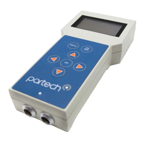
The 740 Monitor is used for processin and displayin the output si nal from a Partech
sensor. It combines a clear display of the measured parameter, a simple user interface,
with ood flexibility to enable confi uration to satisfy the users needs.
1.2 Display
The 740 display indicates the measured value with lar e numerals for ood visibility
with an additional status line that shows the current settin s, battery status and any
faults that are present. The display has a backli ht to enable use of the monitor in low
li ht conditions and also has automatic contrast settin s.
The measurement title, units and display ran e can all be user set to suit the sensor
bein used and the application bein monitored.
1.3 Key Pad
A six key tactile membrane keypad is used for all confi uration and operation of the
740 Monitor; each key has a very positive operation enablin use even whilst wearin
loves.
1.4 Sensors
The 740 Monitor can be used with the Partech Soli-Tech 10 (ST10).
1.5 Manual Conventions
This instruction manual describes the confi uration and operation of the 740 Monitor
and where required includes some information re ardin sensors. It is therefore very
important that it is used in conjunction with the relevant sensor instruction manual. All
dimensions stated in this manual are in millimetres unless otherwise stated.
The manual has been written on the basis that the user has a basic knowled e of
instrumentation and an understandin of the type of measurement bein made.
Trainin in the use of the 740 Monitor can be provided by Partech, please contact
Partech for further information
172430IM-Iss07.odt 172430IM-Iss07 Issue Date 23/10/2014 Page 7 of 46

740 Portable Suspended Solids
Page 8 of 46 172430IM-Iss07 Issue Date 23/10/2014
Figure 1 740 Monitor
C ARGE
S U S P E N D E D S O L I D S
m g / l
1500
Charger
Socket
ON/OFF Key
Charge LED
Sensor
Connection

740 Portable Suspended Solids
2 Basic Operation
2.1 Switching On and Off
The 740 Monitor can be turned on and off usin the ON/OFF key. When the monitor is
turned on it displays a start-up screen prior to enterin Measure Mode. The instrument
can be switched off at any time by pressin the ON/OFF key.
2.2 Measure Mode
The normal operatin mode for the 740 Monitor is measure mode and this is active
when the measured value is displayed in lar e numbers. Whilst in measure mode the
display value is continually updated based upon the current sensor input si nal.
The display in measure mode also includes a status bar that scrolls throu h the status
of the battery, details of the instrument settin s and if the instrument is locked. The
status bar is also used to indicate any instrument faults that are present.
S U S P E N D E D S O L I D S
B a t t e r y = 7 5 %
m g / l
1 5 0 0
Status Text
Measurement Title
Display alue
Units
2.3 Measurement Cycle
The measurement cycle is carried out in the back round at all times when the
instrument is switched on re ardless of whether the instrument is in measure mode or
not. The monitor performs five measurement cycles per second enablin a response
time of one fifth of a second (with dampin rate set to Instant – see dampin ).
2.4 Display
The resolution of the displayed value is determined by the sensor ran e settin , such
that only sensible display values are indicated; the same ran e also determines the
calibration value ran e.
The display units and measurement title are user selectable and should be chosen to
suit the parameter bein monitored and sensor bein used.
172430IM-Iss07.odt 172430IM-Iss07 Issue Date 23/10/2014 Page 9 of 46
Figure 2 Measure Mode Display

740 Portable Suspended Solids
2.5 Profiles
The 740 Monitor allows the user to define up to 10 Profiles, each profile will be based
on a preset confi uration which can be modified to suit the actual measurement
required.
Page 10 of 46 172430IM-Iss07 Issue Date 23/10/2014

740 Portable Suspended Solids
3 Configuration
3.1 Menu Mode
To access the main menu, press the MENU key when the instrument is in measure
mode. Pressin the MENU key when the main menu is displayed will return the
instrument to the measure mode. When the main menu is displayed, the keys can
be used to move the selection bar. Pressin the OK key will activate the selected item.
If the instrument is left in any display other than measure mode, it will automatically
return to measure mode after one minute has passed with no key presses. When a sub
menu is displayed, pressin the MENU key will exit the current menu and return to the
previous menu. If a menu consists of more than six items, UP and DOWN arrows will
appear to indicate if there are menu items above or below those displayed.
3.2 Data Entry
To provide the user with a simple interface, the 740 uses three methods of data entry
for the settin of all the user confi urable parameters. The various methods of user
data entry used on the 740 are described below:
3.2.1 User List Selection
This method of user data entry is used when a selection from a predefined list of option
is required such as sensor type, display ran e and backli ht mode. The list of possible
selections will be displayed and a small tick will identify the current settin . If the list
contains more than five items, small UP and DOWN arrows will appear on the display
to indicate there are more items than that displayed. To make a selection, the selector
bar can be moved usin the keys, to select the required item. Pressin the OK key
will select the hi hli hted item and a small tick will appear next to it. Pressin the
MENU key will exit the list selection menu.
172430IM-Iss07.odt 172430IM-Iss07 Issue Date 23/10/2014 Page 11 of 46
M A I N M E N U
P R O F I L E C O N F I G
M O N I T O R C O N F I G
I N F O R M A T I O N
L O C K I N S T R U M E N T
Menu Title
Menu Items
Selector Bar
Figure 3 Menu Display

740 Portable Suspended Solids
3.2.2 User Value Entry
When a numerical value is to be set, the current value will be displayed with a flashin
cursor. The ran e of adjustment of the value is predefined and therefore only values
within this ran e can be entered. To adjust a value, the keys are used to select a
di it and the keys are used to increment/decrement the di it. When the new value
has been set pressin the OK key will store it and exit from the value adjustment
display. To exit without savin chan es press the MENU key.
Page 12 of 46 172430IM-Iss07 Issue Date 23/10/2014
B L E E P E R
O N
E N T E R U S E R P A S S W O R D
0 0 0 0
U s e t o s e t v a l u e
P r e s s O K t o a c c e p t
P r e s s M E N U t o c a n c e l
Figure 4 List selection Display – note tick indicating current value
Figure Value Entry Display

740 Portable Suspended Solids
3.2.3 User Text Entry
Usin this method of data entry, the user is able to enter or edit text and is used for the
user defined measurement title and units. The text strin is displayed with a flashin
cursor indicatin the selected character. The keys are used to select a character,
and the keys to chan e the selected character. When all chan es are complete
press the OK key to store the text strin . To exit without savin chan es press the
MENU key.
172430IM-Iss07.odt 172430IM-Iss07 Issue Date 23/10/2014 Page 13 of 46
E D I T U S E R T I T L E
A e r a t i o n L a n e 1
U s e t o s e t v a l u e
P r e s s O K t o a c c e p t
P r e s s M E N U t o c a n c e l
Figure 6 Text Entry Display

740 Portable Suspended Solids
4 User Profiles
Understandin the concept of profiles is key to the successful operation of the 740
Monitor. A profile is used to store the confi uration and calibration data for a particular
measurement. The 740 Monitor is capable of storin up to ten profiles, the actual
number required will depend upon the number of different measurements to be made.
Normally a separate profile is required for each different measurement to be made, for
example final effluent suspended solids and mixed liquor suspended solids.
4.1 Presets
To reduce the setup time of the 740 Monitor, several preset measurements are
available that the user can choose from when creatin a new profile. Each of these
presets contains confi uration and calibration data for commonly made measurements.
Note: The presets provide a fast route to co pleting the instru ent setup.
However as they use calibration data established fro reference easure ents,
it ay be necessary to carry out calibration to i prove upon the easure ent
accuracy.
4.2 Example Profile Configuration
Mr Bill Smith has a 740 Monitor which he uses at Charlestown Waste Water Treatment
Works to measure the mixed liquor suspended solids and the final effluent.
The monitor has been set up with two profiles (the remainin profiles are unused) as
shown below:
Profile 1 - Mixed Liquor Suspended Solids
Parameter Value Comment
Profile Name Charlestown MLSS
Profile User Bill Smith
Profile Date 25/12/2001 Date profile created
Measurement Title Suspended Solids
Display Units m /l
Display Ran e 0 - 20000 Typical value 3500m /l
Dampin Rate Medium
Page 14 of 46 172430IM-Iss07 Issue Date 23/10/2014

740 Portable Suspended Solids
Profile 2 - Final Effluent Suspended Solids
Parameter Value Comment
Profile Name Charlestown F.E. Can't fit "Final Effluent"
Profile User Bill Smith
Profile Date 25/12/2001 Date profile created
Measurement Title Suspended Solids
Display Units m /l
Display Ran e 0 - 200 Typical value 2 mg/l
Dampin Rate Medium
172430IM-Iss07.odt 172430IM-Iss07 Issue Date 23/10/2014 Page 1 of 46
740 Portable Suspended Solids
5 Select Profile
To choose which profile to use, the Select Profile option is selected on the main menu.
The ten profiles are listed, if a profile has been setup the profile name is displayed
otherwise the profile is indicated as empty.
The active profile is indicated with a tick. To select another profile use the keys to
move the hi hli ht bar then press the OK key. Information about the profile will be
displayed with a prompt to use the selected profile.
Note: If a profile na e was entered at the ti e the profile was setup this will be
shown, if a na e was not entered the default na e will be displayed e.g. Profile
One. Only the first fifteen characters of a user entered profile na e are
displayed.
Page 16 of 46 172430IM-Iss07 Issue Date 23/10/2014
M A I N M E N U
2 . S t A u s t e l l S T W
3 . < E m p t y >
4 . < E m p t y >
5 . < E m p t y >
M A I N M E N U
2 . S t A u s t e l l S T W
3 . < E m p t y >
4 . < E m p t y >
5 . < E m p t y >
S E L E C T P R O F I L E
C h a r l e s t o w n S T W M L S S
B i l l S m i t h
2 2 / 0 8 / 2 0 0 1
P r e s s O K t o a c c e p t
P r e s s M E N U t o c a n c e l
Figure 7 Select Profile
Figure 8 Selected Profile Information & Confirmation

740 Portable Suspended Solids
6 New Profile Wizard
When the New Profile Wizard is selected you will be taken throu h a series of display
screens that will prompt you to select the correct confi uration for your application. The
selections can be modified after creation by editin the profile.
6.1 New Profile Wizard Keys
Once the Create Profile feature has been entered, the MENU key can be used to exit at
any time. Pressin the key moves forward to the next step and pressin the
moves back to the previous step. Pressin the OK key will activate the displayed
function.
6.2 New Profile Wizard Stages
The Create Profile feature uides the user throu h the confi uration of the followin
items, for more information about the item, refer to the applicable section of this
manual. (* These sta es are shown if the User Defined preset was selected)
172430IM-Iss07.odt 172430IM-Iss07 Issue Date 23/10/2014 Page 17 of 46
7 4 0 P R O F I L E W I Z A R D
U s e t h e 7 4 0 p r o f i l e w i z a r d
t o g u i d e y o u t h r o u g h t h e
s e t t i n g u p o f a p r o f i l e .
N E X T
Y
Figure 1 Profile Wizard
7 4 0 P R O F I L E W I Z A R D
U s e t h e 7 4 0 p r o f i l e w i z a r d
t o g u i d e y o u t h r o u g h t h e
s e t t i n g u p o f a p r o f i l e .
N E X T
Y
Figure 9 Profile Wizard
7 4 0 P R O F I L E W I Z A R D
T h e w i z a r d c a n b e e x i t e d
b y p r e s s i n g t h e m e n u k e y .
N E X T
Y
Figure 10 Profile Wizard

740 Portable Suspended Solids
1. Select Preset
2. Profile Name (up to 21 characters)
3. Profile User (up to 21 characters)
4. Profile Date (dd/mm/yyyy)
5. Measurement Title*
6. Display Units*
7. Display Ran e*
8. Dampin *
On successful completion of the new profile wizard, the calibration of the profile should
be checked, it may be necessary to calibrate the profile. (See Profile Calibration). It
may be necessary to amend some parameters to suit the application.
Page 18 of 46 172430IM-Iss07 Issue Date 23/10/2014
740 Portable Suspended Solids
7 Profile Config
7.1 Profile Name
This menu is used to set/edit the profile name. The profile name should be set to
describe the measurement that the profile has been set up for. For example
"Charlestown STW MLSS".
To edit the profile name, use the keys to select a character, and the keys to
chan e the selected character. When all chan es are complete press the OK key to
store the measurement title. To exit without savin chan es press the MENU key. The
profile name can be up to 21 characters lon .
Note: If the profile na e is not set during the creation of the profile it will be
auto atically na ed "Profile x" where x is the profile nu ber.
7.2 Profile User
This menu is used to set/edit the profile user. The profile user can be used to record
the name of the person who set up the profile.
To edit the profile user, use the keys to select a character, and the keys to
chan e the selected character. When all chan es are complete press the OK key to
store the measurement title. To exit without savin chan es press the MENU key. The
user name can be up to 21 characters lon .
Note: If the profile user is not set during the creation of the profile it will be
auto atically na ed "User x" where x is the profile nu ber.
7.3 Profile Date
The profile date can be set/chan ed usin this menu. The profile date can be used to
record when the profile was created or when the profile was last calibrated.
To edit the profile date, use the keys to select a di it, and the keys to chan e
the selected di it. When all chan es are complete press the OK key to store the
measurement title. To exit without savin chan es press the MENU key.
Note: The profile date will be set to a default value if it is not set when the profile
is created. It is possible to enter non-calendar dates - however this will have no
effect on the instru ents operation.
172430IM-Iss07.odt 172430IM-Iss07 Issue Date 23/10/2014 Page 19 of 46
740 Portable Suspended Solids
7.4 Measurement Title
This menu is used to select the measurement title displayed in measure mode. The
user can select from a list of predefined titles or enter a custom title. To select a
measurement title, use the keys to hi hli ht the required title and press the OK
key. If a predefined title is selected, a small tick will appear next to the selected title. If
the user defined option is selected, a new screen will be displayed which allows editin
of the user defined title.
7.4.1 User Defined Title
To edit the user defined title, use the keys to select a character, and the keys
to chan e the selected character. When all chan es are complete press the OK key to
store the measurement title. To exit without savin chan es press the MENU key. The
user measurement title can be up to 21 characters lon .
7.5 Display Units
The measurement units displayed in measure mode can be selected usin this menu
such that they are appropriate for the measurement bein made. The user can select
units from a predefined list, enter custom units (user defined) or switch off the display
of units.
To select the measurement units, use the keys to hi hli ht the required title and
press the OK key. If a predefined title is selected, a small tick will appear next to the
selected title. If the user defined option is selected, a new screen will be displayed
which allows editin of the user defined units.
7.5.1 User Defined Units
To edit the user defined units, use the keys to select a character, and the keys
to chan e the selected character. When all chan es are complete press the OK key to
store the new units. To exit without savin chan es press the MENU key. User units
can be up to 4 characters lon .
Note: There is no athe atical relationship between FTU and g/l or g/l. If FTU
are used, For azin should be used for calibration.
Page 20 of 46 172430IM-Iss07 Issue Date 23/10/2014
Table of contents
Other ParTech Measuring Instrument manuals
Popular Measuring Instrument manuals by other brands

PCB Piezotronics
PCB Piezotronics EX357A94 operating guide

Teledyne Lecroy
Teledyne Lecroy WaveRunner 8000-R Getting started guide

Endress+Hauser
Endress+Hauser Liquiline CA80SI Brief operating instructions

Konica Minolta
Konica Minolta CR-20 instruction manual

Christ Elektronik
Christ Elektronik CPM138-AC instruction manual

madur electronics
madur electronics GA-12 manual