Energomera CE308 User manual

СЕ308
САНТ.411152.107-05.1 РЭ
Operation Manual
Manufacturer:
Electrotechnical Factories Energomera JSC
415 Lenina Str., Stavropol, Russia 355029
Tel.: (8652) 35-75-27, Fax: 56-66-90,
Hot line (free): 8-800-200-75-27
e-mail: concern@energomera.ru
www.energomera.ru
Warranty service:
217 Gagarina street, Nevinnomyssk,
Stavropol region, 357106
Electric energy meter
Three-phase multifunctional
Case type S31, S34
OKP 42 2863 6
Harmonized System Codes (TN VED) 9028301 100

2

2 3
CONTENTS
1 SAFETY REQUIREMENTS ...................................................................................................................................5
2 METER DESCRIPTION ........................................................................................................................................6
2.1 Purpose .............................................................................................................................................................. 6
2.2 Designation of meter modifications ..................................................................................................................... 9
2.3 Certification Information ...................................................................................................................................11
2.4 Normal usage conditions: .................................................................................................................................12
2.5 Operating usage conditions ..............................................................................................................................12
2.6 Ambient conditions ..........................................................................................................................................13
2.7 Technical specifications .....................................................................................................................................13
2.8 Meter design ....................................................................................................................................................19
3 PREPARING THE METER FOR OPERATION....................................................................................................... 20
3.1 Unpacking ........................................................................................................................................................20
3.2 Preparing for operation .....................................................................................................................................20
3.3 Installation procedure .......................................................................................................................................20
3.4 Wiring diagrams ...............................................................................................................................................21
3.5 Lithium cell replacement ...................................................................................................................................35
3.6 Meter configuration ..........................................................................................................................................36
4 READING THE METER .................................................................................................................................... 36
4.1 Displaying information on the LCD ....................................................................................................................36
4.2 Viewing total accumulated values (on an accrual basis) .....................................................................................39
5 METER VERIFICATION .................................................................................................................................... 46

4
6 MAINTENANCE AND SEALING....................................................................................................................... 46
7 ROUTINE MAINTENANCE .............................................................................................................................. 47
8 STORAGE AND TRANSPORTATION CONDITIONS ............................................................................................ 48
9 CONTAINERS AND PACKING .......................................................................................................................... 48
10 LABELING .................................................................................................................................................... 49
ANNEX A .......................................................................................................................................................... 51
ANNEX B .......................................................................................................................................................... 52
ANNEX C .......................................................................................................................................................... 54

4 5
This САНТ.411152.107-05.1 РЭ (Operation Manual) contains brief information on CE308 S31, CE308 S34
multifunctional three-phase electric meter (hereinafter referred to as the «Meter»). Complete information on the
above meter is contained in САНТ.411152.107-05.1 РП (User Manual), which can be found at the manufacturer’s
website: www.energomera.ru/ru/products/meters/ce308-all
When learning about the meter and operating it, you must be additionally guided by
САНТ.411152.107-05.1 ФО (Technical passport) (included in the meter delivery kit) and САНТ.411152.107-05.1
РП (User Manual).
Only persons who have received special training for working with voltages up to 1000 V and who have studied
the Operation Manual are allowed to work with the meter.
1 SAFETY REQUIREMENTS
1.1 By operational safety, the meter meets the safety requirements of GOST 22261-94 and IEC 61010-1:2001.
1.2 According to the method for protecting a person from electric shock, the meter corresponds to class II of
IEC 61010-1:2001.
1.3 The insulation between all current and voltage circuits connected together and with the «ground» can
withstand a voltage of 4 kV AC at 50 Hz for 1 minute. During the test, the leads of the electrical test output device,
the interface circuits are connected to the «ground» (the «ground» is a conductive foil film enclosing the meter and
attached to a flat conductive surface on which the meter base is mounted).
For transformer connection meters, the insulation withstands a voltage of 4 kV AC at 50 Hz for 1 minute, when
applied between current circuits connected together and voltage circuits connected together.
1.4 For transformer connection meters, the insulation between each current circuit and all other meter circuits
connected to the «ground»; between each voltage circuit and all other meter circuits, including the common voltage
circuit output connected to the «ground», withstands pulse voltage of 6 kV.
The insulation between all current and voltage circuits connected together and with the «ground» can withstand
pulse voltage of 6 kV. During the test, the leads of the electrical test output device must be connected to the «ground».

6
1.5 Insulation resistance between the casing and electrical circuits, at least:
20 MΩ — under conditions of clause 2.5;
7 MΩ – at an ambient air temperature (40±2) °С, relative air humidity of 93%.
1.6 The meter must be installed and operated in accordance with the applicable rules for technical operation of
electrical installations.
1.7 Do not put foreign objects on the meter, avoid bumps.
2 METER DESCRIPTION
2.1 Purpose
The meter is three-phase, transformer connection or direct connection (depending on the version), it is designed
to measure active and reactive electrical energy in three-phase four-wire AC circuits.
The meter has the following functions:
• multi-tariff electricity metering (with three tariffing levels - event-based, external and time-based tariffing);
• maintenance of the retrospective (recording the current values of energy storage devices: at the end of the
billing period (month), at the end of the day, at the end of the year and upon occurrence of a specific event);
• maintaining a load profile, with the ability to customize the type of the parameters stored and the averaging
time;
• measuring network parameters: voltage frequency, phase currents, phase voltages, phase-to-phase (line)
voltages (with non-standardized accuracy), angles between current and voltage by phases; power factor by phases
and the three-phase power factor, active, reactive, full power by phases and total;
• measuring Unified Power Quality Index (UPQI) in accordance with class «S» of the measurement process
specifications in IEC 61000-4-30:2008: stable voltage deviation, network frequency deviation, duration and depth
of voltage dips, duration and maximum value of overvoltage, interruptions in power supply;
• power quality analysis for compliance with quality standards in accordance with EN50160:2010;
• indicating the instance of violating an individual power quality indicator on the LCD (disabled by default);

6 7
• recording the violation of an individual power quality indicator (event logs available for reading on the interface);
• monitoring active power consumption;
• monitoring «instantaneous power» consumption;
• monitoring active energy consumption (control of energy limits, prepaid mode, low consumption control);
• monitoring mains voltage;
• monitoring currents;
• monitoring network frequency;
• monitoring phase sequence;
• monitoring phase break;
• monitoring oncoming power flow;
• alarm relay (in the versions of the meter with an alarm relay (see Table 2.2));
• telemetric outputs with the ability to use them as a «relay»;
• alarm using the interface (the ability to act as an initiator of communication with the level of DCU or HES during:
terminal cover opening; exposure to a magnetic field; reparameterization; maximum power excess; deviation
from the normalized value of voltage level, etc., in accordance with the full list, for details, see the user manual
САНТ.411152.107-05.1 РП;
• time accounting;
• self-diagnostics;
• information protection;
• protection against unauthorized opening (electronic seals);
• magnetic field sensor;
• event logs with recording of: terminal cover opening; case opening; dates of last re-programming; exposure
to a magnetic field causing unacceptable deviations of the metrological characteristics of the metering device; facts
of communication with the metering device that led to data changes; voltage deviations from the device’s nominal
values in the measuring circuits; results of self-diagnostics; changes in the current values of time and date during
time synchronization (at least 3,500 records using the DLMS/COSEM protocol.), etc., for details, see the user

8
manual САНТ.411152.107-05.1 РП;
• mechanism for flexible adjustment of the reaction to events occurring in the meter;
• DLMS/COSEM exchange protocol support;
• display of information on the LCD accompanied by OBIS codes;
• IEC 60870-5-104-2004 exchange protocol support;
• management of consumer load according to a predefined schedule.
A detailed description of meter functions is given in the full version of САНТ.411152.107-05.1 РП (User
Manual).
The meter can be used in Automatic Informational and Measuring Systems for Commercial Electric Power
Accounting (AMI systems) to transfer the measured or calculated parameters to the control room for controlling,
accounting and distributing electric power.
The measurement results are obtained through processing and calculating current and voltage input signals
performed by the microprocessor circuit on the meter board. The measured data and other information are displayed
on a liquid crystal display (LCD) and can be transmitted via an optical port, using one or two additional interfaces.
The meter has 2 communication channels. The PLC G3 communication module in metering devices operates on
the principle of a mesh network and provides search for duplicate routes for the guaranteed transmission of the
collected information.
The meter has an electronic counting mechanism which, depending on the established current and voltage
transformation ratios, records active and reactive energy in kW•h and kVar•h, respectively, overall and according to
eight tariffs in two directions.
Changing time of the counting mechanism indications complies with the requirements of IEC 62052-11:2003,
IEC 62053-21:2003 (IEC 62053-22:2003) and IEC 62053-23:2003.

8 9
2.2 Designation of meter modifications
2.2.1 The structure of meter designation is shown in Fig. 1.
СЕ308 XX.ХXХ.XХ.XXX XXXX
Designation of the integrated communication module
Additional functions:
See Table 2.1.
Integrated communication interfaces:
See Table 2.1.
Nominal or base (max.) current:
3 – 5(10) А;
5 – 5(60) А;
6 – 5(100) А.
Nominal voltage (phase/line):
0 – 3x57.7/100 V;
4 – 3x230/400 V.
Active/reactive energy accuracy class:
4 – 0.2S/0.5
5 – 0.5S/0.5;
7 – 1/1.
Body type and number:
S31, S34 – for installing in a service panel.
Figure 2.1 – Designation structure

10
Table 2.1
Designation Interface Designation Additional software and hardware
options
O* Optical interface (OI) S Alarm relay
B M-BUS Q Load control relay
E RS232 Y 2 metering directions
A RS485 D External display
PPLC U Power quality parameters
G GSM V* Electronic seals
N Ethernet J Optional connection of a backup
power source
R1 Radio interface with
a built-in antenna
L LCD backlighting
F Magnetic field sensor
R2 Radio interface with
an external antenna Z Extended set of parameters
* – by default, included in all meter versions
2.2.2 Meter versions, accuracy classes, the meter constant and the position of the comma when displaying
energy values on the LCD, depending on the nominal voltage (U
NOM
), nominal (I
NOM
) or base (I
b
) and maximum
(I
MAX
) current, are shown in Table 2.3.

10 11
Table 2.2
Designation
of meters
Accuracy
class
Nominal
voltage, V
Nominal,
base (max.)
current, A
Meter constant
imp/(kW•h),
imp/(kVar•h)
Point
position
(by default)
СЕ308 S31 403 Х…X 0.2S/0.5 3х57.7/100 5 (10) 8000 00000.000
CE308 S31 503 Х...Х 0.5S/0.5 3x57.7/100 5 (10) 8000 00000.000
CE308 S31 543 Х...Х 0.5S/0.5 3x230/400 5 (10) 4000 00000.000
CE308 S31 745 Х...Х 1/1 3x230/400 5 (60) 800 000000.00
CE308 S3x 746 Х...Х 1/1 3x230/400 5 (100) 450 000000.00
2.2.3 Example of a meter inscription
When ordering a meter, the required version is determined by the structure of the designation shown in Figure 1.
A meter inscription example: a meter for installation into an electric service panel, accuracy class 1 for active
energy and 1 for reactive energy (7), with nominal voltage of 230 V (4), with base current 5 A and maximum
current 100 A (6), with an optical port (O), with an RS485 interface (A), with an alarm relay (S), for two measuring
directions (Y), measuring power quality parameters (U), with a lid opening control (V), with an indicator light
(L), with a magnetic field sensor (F) and an extended set of parameters (Z): «CE308 S31.746.OA.SYUVLFZ
multifunctional three-phase electric meter, TУ 4228-104-78189955-2014».
2.3 Certification Information
Information on meter certification is given in the САНТ.411152.107-05.1 ФО.

12
2.4 Normal usage conditions:
– ambient air temperature (23±2) °С;
– ambient air relative humidity (30-80) %;
– atmospheric pressure from 70 to 106.7 kPa (537...800 mm Hg).
– network frequency (50±0.5) Hz;
– the shape of the voltage curve of the measuring network is sinusoidal with a nonsinusoidal factor according to
GOST EN50160:2010*.
2.5 Operating usage conditions
The meter is connected to a three-phase AC network and installed indoors (or in cabinets with environmental
protection) with operating usage conditions:
– temperature range minus 40 to plus 70 °С
– ambient air relative humidity (30-98) %;
– atmospheric pressure from 70 to 106.7 kPa (537-800 mm Hg).
– network frequency (50 ± 2.5) Hz;
– the shape of the voltage curve of the measuring network is sinusoidal with a nonsinusoidal factor according to
EN50160:2010*.
*ATTENTION! WHEN OPERATING METERS IN CONJUNCTION WITH A POWERFUL NON-LINEAR LOAD
WHICH CAN DEGRADE THE POWER QUALITY (FOR EXAMPLE, AN ELECTRIC DRIVE WITH A FREQUENCY
CONVERTER), YOU SHOULD USE SPECIAL FILTERING DEVICES.
OTHERWISE, THE METER MAY OVERHEAT AND FAIL. FAILURE OF THE METERS DUE TO POOR POWER
QUALITY IS NOT A WARRANTY CASE. THE MANUFACTURER IS NOT RESPONSIBLE FOR DAMAGE TO THE
CONSUMER’S PROPERTY RESULTING FROM VIOLATION OF THE OPERATING CONDITIONS OF THE METERS
DESCRIBED IN THIS OPERATION MANUAL, INCLUDING DUE TO A POOR POWER QUALITY.

12 13
2.6 Ambient conditions
2.6.1 In terms of resistance to climatic influences, the meter belongs to group 4 in accordance with
GOST 22261-94, with an extended range of temperature and humidity, satisfying version T category 3 in
accordance with GOST 15150-69.
In terms of resistance to mechanical impacts, the meter belongs to group 2 according to GOST 22261-94.
2.6.2 In terms of protection against ingress of dust, water and external solid objects, the meter case corresponds
to the degree of protection IP54 according to IEC 60529:2013. In case of outdoor use, the meter must be installed
inside a protective box, protecting it from direct exposure to sunlight, precipitation and not allowing the temperature
of the air surrounding the meter to rise above plus 70 ° C.
2.6.3 The meter is resistant against single impacts with a maximum acceleration of 300 m/s
2
.
2.6.4 The meter is resistant to vibrations in the frequency range (10-150) Hz.
2.6.5 The meter body withstands impact of spring hammer blows with kinetic energy (0.20±0.02) J applied to
the external surfaces of the body, including the windows, and to the lid of the clamps.
2.6.6 Parts and components of the meter that are designed for operation in areas with a tropical climate, in terms
of resistance to the effects of mold fungi, comply with the requirements of GOST 9.048-89.
The permissible growth of fungi amounts up to 3 points according to GOST 9.048-89.
2.7 Technical specifications
2.7.1 The meters meet the requirements of IEC 62052-11:2003, IEC 62053-21:2003 (for class 1),
IEC 62053-22:2003 (for classes 0.2S and 0.5S) in terms of measuring active energy, and IEC 62053-23:2003 in
terms of measuring reactive energy.
2.7.2 The technical specifications given with tolerances or limit values are considered guaranteed. Values without
tolerances are for reference only.
Main technical specifications are given in Table 2.4.
Limits of the permissible errors of the measured values are given in Annex A.

14
Table 2.3
Specification name Specification value Note
Nominal (max.) currents 5(10) А Transformer connection
Base (max.) currents 5(60); 5(100) Direct connection
Nominal phase voltage 57.7 V; 230 V Transformer connection
230 V Direct connection
Operating phase voltage (0.6 (0.75)*...1.21) Unom V * — for meters with 57.7 V
nominal voltage
Nominal network frequency (50±2.5) Hz
Non-sinusoidal factor of the measuring
network voltage, %, max – In accordance with EN50160:2010
Sensitivity threshold
Direct
connection
Transformer
connection Active/reactive energy
– 0.001 Inom A 0.2S/0.5; 0.5S/0.5
0.002 Ib A 1/1
Number of decimal places on the LCD from Table 2.2
Total power consumed by each current
circuit, max 0.1 (V•A) With nominal (base) current

14 15
Specification name Specification value Note
Total (active) power (consumed by
each voltage circuit at nominal voltage,
max
9(V•A) (0.8 W) Transformer connection
Active power consumption
of communication modules, max 3 W at nominal voltage
Limit of the clock basic absolute error ±0.5 s/day Transformer connection
Manual and system correction,
clock rate ±29 s max 29 s per day
Limit of the clock additional
temperature error
±0.15 s/°C•day From minus 10 to 45 °С
±0.2 s/°C•day From minus 40 to minus 10 °С
and from 45 to plus 70 °С
Duration of information storage when
power is off 30 years
Built-in lithium cell service life 16 years It is possible to install an additional
external lithium cell (see section 3.5)
Additional external lithium cell
service life 5 years
Number of tariffs up to 8
Table 2.3 (continued)

16
Specification name Specification value Note
Number of tariff zones in a day up to 16
Number of seasonal schedules in a year up to 12
Number of exclusive days up to 80
Number of daily rate scales up to 32
Number of power control zones
in a day 3
Number of power control schedules up to 12
Power averaging time 1; 2; 3; 4; 5; 6; 10; 12; 15;
20, 30, 60 min
Depth of monthly energy storage
by tariffs and phases 40 months Current and 39 previous
Depth of daily energy storage,
accumulated by tariffs and phases 128 days Current and 127 previous
Depth of annual energy storage,
accumulated by tariffs and phases 10 years Current and 9 previous
Depth of event energy storage by tariffs
and phases 20 events
Table 2.3 (continued)

16 17
Specification name Specification value Note
Depth of monthly maximum power
storage in the three control zones 13 months Current and 12 previous
Number of parameters in a profile up to 6
Profile storage depth, days 1128 With an averaging time
of 60 minutes
Averaging time of load profiles 1; 2; 3; 4; 5; 6; 10; 12; 15;
20, 30, 60 min
Event logs – For details, see
САНТ.411152.107-05.1 РП
Nominal (permissible) voltage of
electrical pulse outputs, max 10 (24) V DC voltage
Nominal (permissible) current value
of electrical pulse outputs, max 10 (30) mA DC voltage
Duration of output pulses 35 ms In a TM mode
Interface communication speed From 300 to 19,200 bd Depending on the characteristics
of the communication modules
Optical port communication speed From 300 to 19,200 bd
1The profile storage depth is directly proportional to the averaging time with reduction to the integer part.
Table 2.3 (continued)

18
Specification name Specification value Note
Meter update time 1 s
Initial start, max 5 s From the moment the voltage is
applied
Meter weight, max 3 kg for CE308 S31, S34
Overall dimensions (height; width;
length), max, mm
72х175х215 for CE308 S31
85х175х280 for CE308 S34
Mean time to failure 220,000 h
Average service life 30 years
Meter cover and terminal block cover
opening control
Meter cover and terminal
cover opening logs
Protection against unauthorized access Meter password, hardware
lock
Maximum current at the relay contacts
during the turn-off (turn-on) opera-
tion, does not exceed
1.1 Imax А
Permissible switching voltage on the
alarm relay contacts, max
265 V AC; 30 V DC in the
S version
Table 2.3 (continued)

18 19
Specification name Specification value Note
Permissible value of switching current
on the contacts of the alarm relay (ver-
sion S), max
2 А CE308 S31
Permissible switching voltage on the
load control relay contacts (version
Q), max
265 V AC; CE308 S34
Switching wear resistance of relay
contacts, cycles 5000 CE308 S34
2.8 Meter design
The meter design complies with the requirements of IEC 62052-11:2003 and the manufacturer’s drawings.
The meter is made in a plastic body.
The appearance of the meter is given in Annex B.
On the front panel of the meter, there are the following:
• liquid crystal indicator;
• one indicator of active energy metering and one indicator of reactive energy metering;
The indicators operate at the frequency of the main transmitter. The indicators can be used to calibrate the meter;
• indicator of functioning;
• optical port elements;
• «FRAME», «VIEW» and «ACCESS» buttons;
In order to access the «ACCESS» button (programming permission), you need to remove the seal of the energy
supplying company that installed the meter, unscrew the fastening screw of the additional cover and remove it;
Table 2.3 (continued)

20
The terminals for connecting the meter to the network, to interface lines and to pulse outputs are closed with a
transparent terminal cover.
3 PREPARING THE METER FOR OPERATION
3.1 Unpacking
3.1.1 After unpacking, inspect the meter visually, verify that there are no mechanical damages, and check the
presence and integrity of the seals.
3.2 Preparing for operation
3.2.1 The meters produced by the manufacturer have factory settings. Changes to factory settings are made in
accordance with the САНТ.411152.107-05.1 РП by companies authorized to configure the meter.
ATTENTION! PRESENCE OF READINGS ON THE METERING DEVICE IS CAUSED BY CHECKING THE METER
AT THE MANUFACTURER’S, AND DOES NOT ATTEST TO ITS WEAR OR OPERATION.
3.3 Installation procedure
3.3.1 Connect the electric meter to a three-phase AC network with a rated voltage indicated on the meter panel.
To do this, remove the terminal cover of and connect the lead wires by securing them in the terminals of the block
according to the wiring diagram printed on the cover, or on the front panel, or in Annex C.
When installing a meter, the wire (cable)
2
must be stripped of insulation to approximately the amount shown in
Table 4. The stripped part of the wire should be smooth, without bends. Insert
the wire into the terminal clamp without tilts. It is not allowed to get a wire with insulation into the clamping area,
as well as for the stripped area to protrude outside the block. First, tighten the top screw. Pull the wire lightly to make
sure that it has been clamped. Then tighten the bottom screw. After several minutes, tighten the connection again.
The diameter of the wires connected to the meter is shown in Table 3.1.
2
The range of the wire diameter is specified based on the possibility of its connection to the meter block. The required cross-section
(and therefore the diameter) of the wire is selected depending on the value of the maximum current.
Other manuals for CE308
1
This manual suits for next models
2
Table of contents
Other Energomera Measuring Instrument manuals
Popular Measuring Instrument manuals by other brands
JAVAC
JAVAC JAV-1041 Safety instructions & operation manual
DI-BOX
DI-BOX FLOWBOX user manual
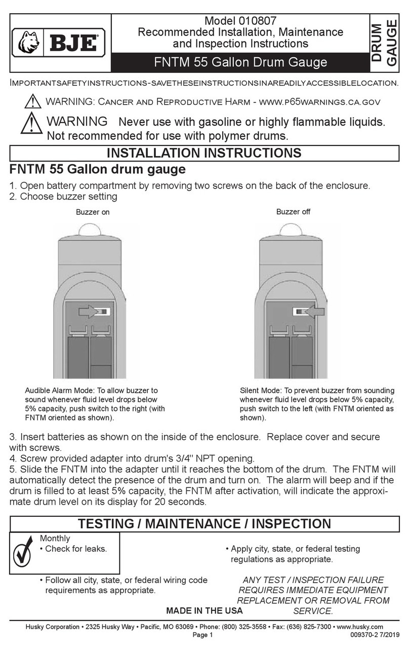
BJE
BJE 010807 Recommended Installation, Maintenance and Inspection Instructions
Sealey
Sealey VS0563 instructions
Sky Control
Sky Control SC8100 Configuration manual
MADDALENA
MADDALENA ElecTo Bulk Instructions for installation, use and maintenance


