Bently Nevada 3300/15 User manual

Artisan Technology Group is your source for quality
new and certied-used/pre-owned equipment
• FAST SHIPPING AND
DELIVERY
• TENS OF THOUSANDS OF
IN-STOCK ITEMS
• EQUIPMENT DEMOS
• HUNDREDS OF
MANUFACTURERS
SUPPORTED
• LEASING/MONTHLY
RENTALS
• ITAR CERTIFIED
SECURE ASSET SOLUTIONS
SERVICE CENTER REPAIRS
Experienced engineers and technicians on staff
at our full-service, in-house repair center
WE BUY USED EQUIPMENT
Sell your excess, underutilized, and idle used equipment
We also offer credit for buy-backs and trade-ins
www.artisantg.com/WeBuyEquipment
REMOTE INSPECTION
Remotely inspect equipment before purchasing with
our interactive website at www.instraview.com
LOOKING FOR MORE INFORMATION?
Visit us on the web at www.artisantg.com for more
information on price quotations, drivers, technical
specications, manuals, and documentation
Contact us: (888) 88-SOURCE | sales@artisantg.com | www.artisantg.com
SM
View
Instra

•
3300/15
DUAL VIBRATION
MONITOR
•MAINTENANCE MANUAL
•
BENTLYr\
NEVADA \.)
DOCUMENT NO. 80177-01
•.
db

NOTICE
READ THE FOLLOWING BEFORE INSTALLING OR OPERATING EQUIPMENT.
Bently Nevada Corporation has attempted to identify areas of risk created
by improper installation and/or operation of this product. These areas of in—
formation ore noted as WARNING or CAUTION for your protection and for the
safe and effective operation of this equipment. Read all instructions before
installing or operating this product. Pay particular attention to those areas
designated by the following symbols.
AN WARNING
High voltage present
could cause shock
burns or death
Do not touch exposed
wires or terminals
C.M710H
Machine Protection Could
Be Discontinued
IN THIS DOCUMENT PROCEDURES ARE GIVEN ONLY FOR ONE CHANNEL.
PROCEDURES FOR OTHER CHANNELS ARF SIMILAR EXCEPT FOR THE
OBVIOUS SUBST1 TUTION OF CORRESPONDING S WI TCHES, TERMINALS,
AND INDICA TORS.
SYMBOLS
Special symbols are used in the manual to illustrate specifics in the step—by—
step process. For example:
PRESS FLASHING CONNECT DISCONNECT
TEST EQUIPMENT (Recommended)
Digital Multimeter
660
4I :2 1)1,J.1
tc, 1000 Vac/Vilc
0to 10 mesicihrns
Function Generator
rrecitAta( y Pan9c,
01 to 'a MIIl
Offset ,i10 Vdr
OBSERVE SCREWDRIVER
TK3 Calibration
Instrument
Bently Nevado Corpora-ton
etil$017
II • a
0
11(3-21: ap0/e20
50/60 liZ
IK3-26 (40 to 90 psi
f?15 Sid ,:fn no xi
1S I D 2
•
•

Dual Vibration Maintenance 80177-01
•
•
•
FOREWORD
This document is for maintenance personnel who install and maintain the 3300 Monitoring System. The procedures
presented should aid service personnel to maintain a Dual Vibration Monitor in a typical 3300 System.
RELATED DOCUMENTS
•3300 System Overview, 80171
•3300 System Installation Instructions, 80172
• 33(X) System Troubleshooting, 80173
•3300 Power Supply, 80174
• 33(X) System Monitor, 80175
•3300 Dual Vibration Monitor Operation, 80176-01
•Dynamic Data Manager System, 46390-01
Keyphasor® is a registered trademark of Bently Nevada Corporation
l'roxirnitor® is a registered trademark of Bently Nevada Corporation
Bently Nevada Part No. 80177-01 • First Printing: November 1987
Revision F: April 1990
Copyright © 1987, 1988, 1990 Bently Nevada Corporation
All Rights Reserved
No part of this publication may be reproduced, transmitted, stored in a retrieval system nor translated into any human
or computer language, in any form or by any means, electronic, mechanical, magnetic optical, chemical, manual, or
otherwise, without the prior written permission of the copyright owner,
Bendy Nevada Corporation
P. O . Box 157
Minden, Nevada 89423 USA
Telephone : 702-782-3611
Telex: 7400983 BNC UC
Fax: 702-782-9253
Copyright infringement is a serious matter under
United States of America and Foreign Copyright Laws
iii

80177-01 Dual Vibration Maintenance
Blank Page
iv

Dual Vibration Maintenance 80177-01
•
•
•
CONTENTS
TITLE SECTION
DUAL VIBRATION MONITOR SYSTEM 1
MONITOR FUNCTIONS 2
MONITOR OPTIONS 3
PROGRAMMABLE OPTIONS 4
OK 5
BYPASS 6
ALERT 7
DANGER 8
MONITOR RANGES 9
READ CHANNEL VIBRATION 10
READ PROBE GAP VOLTAGE 11
READ ALERT SETPOINT LEVELS 12
READ DANGER SETPOINT LEVELS 13
SELF TEST 14
DISASSEMBLY PROCEDURE 15
FRONT PANEL REMOVAL 16
SIGNAL INPUT RELAY MODULES 17
INSTALLED PROGRAMMABLE OPTIONS 19
FIRST OUT, ALARM DELAYS, FREQUENCY RESPONSE OPTIONS 20
ALERT MODE, DANGER MODE, DANGER VOTING OPTIONS 21
RECORDER OUT, MONITOR OK LIMITS, DANGER BYPASS SWITCH 22
REPLACE METER SCALE 23
MONITOR FULL SCALE OPTIONS 24
EXPANDER BOARD INSTALLATION/REMOVAL 25

80177-01 Dual Vibration Maintenance
CONTENTS (Continued)
TITLE SECTION
ALARM SETPOINT ADJUST 25
CHANNEL BYPASS 26
DANGER BYPASS 27
TEST CHANNEL ALARMS
CALIBRATE CHANNEL 39
TEST OK LIMITS 30
FIELD WIRING DIAGRAMS 31
RECOMMENDED SPARE PARTS 32
SPECIFICATIONS 33
SCHEMATICS AND DRAWINGS 34
vi

Dual Vibration Maintenance
0OK 0
0DANGER 0
A0 ALERT 013
0BYPASS 0
80177-01
•
•
1DUALVIBRATIONMONITORSYSTEM
3300/15
VIBRATIONMONITOR
73
—a-— —
-—- L
S2— —25
P— P
——
A— - — A
0— — —
P_ - _- r
f_ _ E
—_
—1
o—
DANGER ALERT
GAP
BUFFERED 7DUCERS
0°0 it
®6®
di
6
1.••=.••••••
/7 LI
3300 RACK
CHANNEL A
RECORDER
OUTPUT
ALERT
RELAY
CONTACTS
PROXIMITOR
PROXIMITOR
1L
J
ACI1 kRICIRD *WKS
0
PE
RF
KC
0
wr
0
0
KAM Er MINIS
CHANNEL A...-----v.
PROBE
:=E
CHANNEL B
PROBE
CHANNEL B
RECORDER
OUTPUT
DANGER
RELAY
CONTACTS
SIGNAL INPUT RELAY
MODULE
(REAR OF RACK)
SHAFT
• 1SI D3
1

80177 01 Dual Vibration Maintenance
MONITORFUNCTIONS
RADIAL VIBRATION - Radial vibration is defined as shaft dynamic motion in a direction perpendicular to the shaft
centerline. The Dual Vibration Monitor displays vibration values for two channels (Channels A and B).
PROBE GAP VOLTAGE - Probe gap is measured as a negative dc voltage that is directly proportional to the gap
distance between the face of a proximity probe and the surface being monitored. Probe gap voltage for each chan-
nel is displayed on the front panel meter by pressing the GAP switch.
OK - When the Proximitor output voltage is within its upper/lower OK voltage limits, the transducer is defined as
OK. The OK detection circuit controls the channel OK LED and the monitor relay drive to the OK relay.
OK RELAY - The OK Relay is located on the Power Input Module. Every channel in the rack must be OK or
bypassed to energize the OK Relay.
TIMED OK/CHANNEL DEFEAT - Timed OK/Channel Defeat prevents faulty transducer wiring from causing false
alarms. If the probe input signal level on a given channel is not within upper/lower limits, that channel OK LED
goes off, the BYPASS LED goes on, the channel is disabled, and the OK- Relay deenergizes. If the channel input
signal level is restored within the upper/lower OK limits for 30 seconds, the channel OK LED will start flashing at 1
Hi to indicate the OK state is restored, the BYPASS LED goes off and monitoring is enabled. The RESET switch
on the front panel of the System Monitor must be pressed to stop the OK LED from flashing (it remains on). If the
channel remains in the NOT OK state, a Channel Bypass switch on the monitor circuit board can be set to put the
channel "out of service". The monitor can then be operated as a single-channel monitor. Without this feature, the
OK Relay could not be reactivated. In the Timed OK/Channel Defeat and Channel Bypass modes, there is no
recorder output and the meter registers zero.
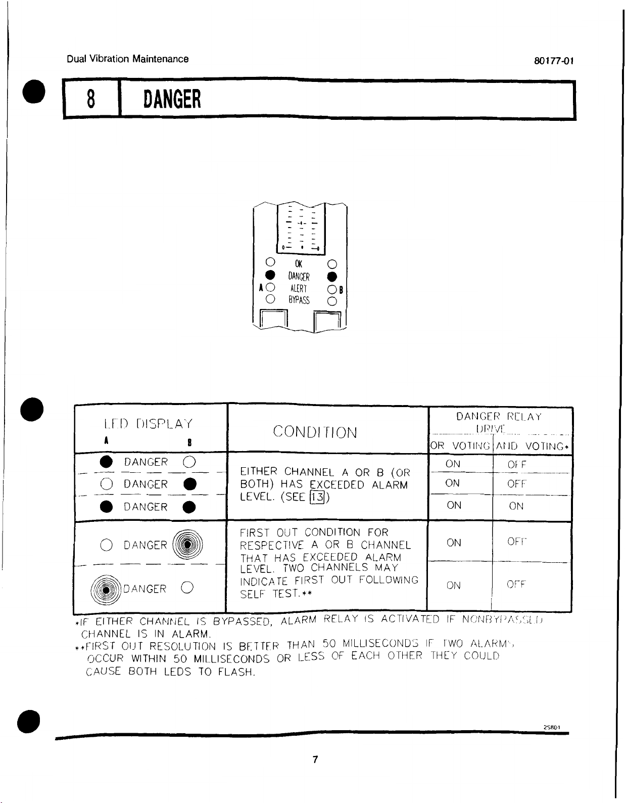
ALARM - Pressing the ALERT or DANGER switch on the front panel of the monitor causes the corresponding
Alert (first-level alarm) or Danger (second-level alarm) alarm setpoints on each channel to be displayed on the front
panel meter. ALERT and DANGER LEDs light when the vibration signal level exceeds preset levels for the
selected time delay, and appropriate Alert and Danger alarm relay contacts are activated. Voting logic options
determine when the Danger alarm relay contacts are activated.
FIRST OUT - Separate First Out circuits exist for Alert and Danger alarms. A monitor with First Out option
selected flashes a channel alarm LED if that channel was the first channel in the rack to go into alarm. Pressing the
RESET switch acknowledges the First Out condition. This allows the next channel in the rack that goes from non-
alarm-to-alarm condition to indicate First Out by flashing its alarm LED.
ALARM RELAYS - Monitor alarms can be programmed for either latching or nonlatching mode. In the nonlatching
mode, the alarm resets automatically when the alarm no longer exists. In the latching mode, the alarm condition
must be reset manually by pressing the RESET switch on the front panel of the System Monitor (or by closing
external Reset contacts). The alarm will not reset if the alarm condition still exists.
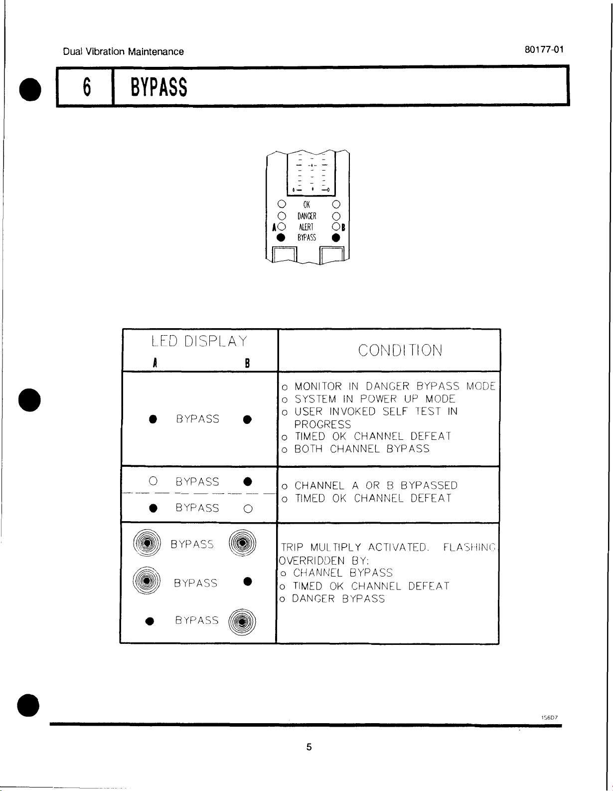
DANGER BYPASS - For maintenance functions, a DANGER BYPASS switch on the monitor circuit board is set to
inhibit the Danger relay drive. This function turns on the BYPASS LEDs. Other front panel functions arc not
effected. This function can be disabled using a jumper within the monitor.
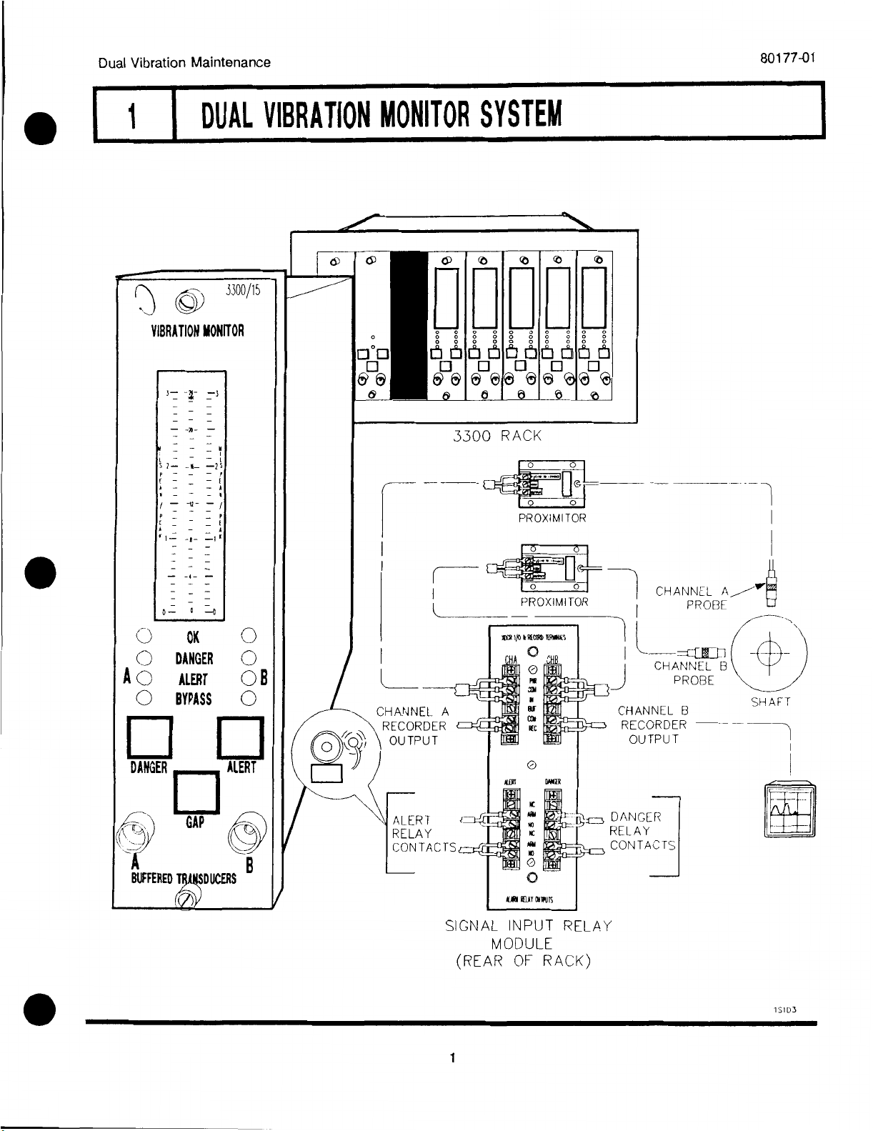
BUFFERED OUTPUT - The Channels A and B coaxial cable connectors on the front panel of the monitor and
terminals on the Signal Input Relay Module provide buffered signals from the respective channel transducers.
These connectors can be used for connection of external equipment.
TRIP MULTIPLY - The Trip Multiply function multiplies set points by 2X or 3X in response to an external contact
closure through terminals on the Power Input Module. The front panel meter and recorder outputs could saturate
in this mode.
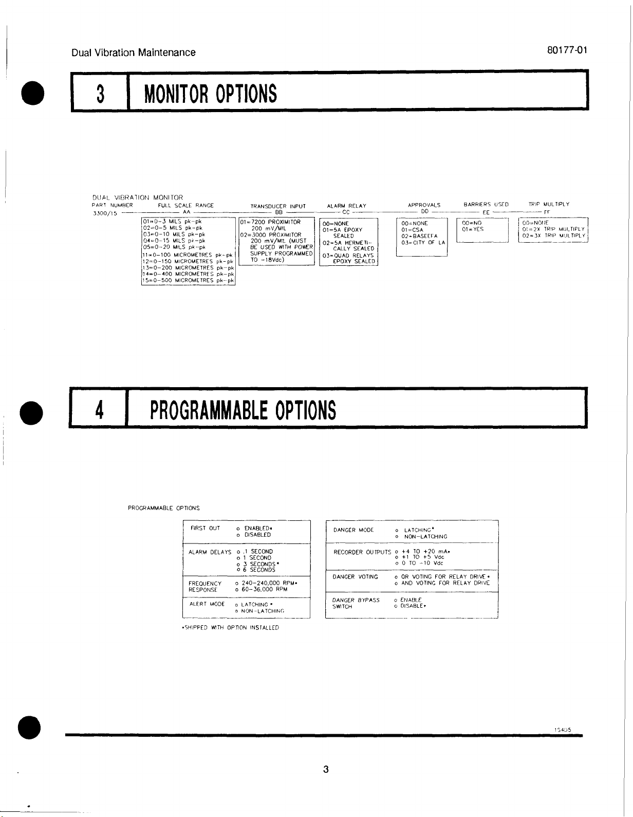
RECORDER OUTPUTS - Depending on the option selected, the recorder output levels proportional to measured
vibration are either 0 to -10 Vdc, +1 to +5 Vdc, or +4 to +20 mA.
SELF TEST - The monitor has three categories of self test: cyclic, power up, and user invoked.
•Power up self test is performed automatically each time the monitor power is turned on. A series of basic
tests and transducer OK tests are performed. upon completion of the tests, if no errors, the monitor will
perform timed OK/Channel Defeat and monitoring will resume in 30 seconds.
• Cyclic self tests is performed automatically during monitor operation. Errors encountered during cyclic tests
disable the monitor, and flash a lcd bargraph error code. Should the error be intermittent the monitor will
return to operation, but the error codes arc stored for retrieval during user-invoked self tests. Stored error
codes are indicated by OK LED's flashing at 5 HZ provided that the channel is OK
•User invoked test performs power up self test and allows error messages stored during cyclic tests to be read
and cleared. Stored errors arc annunciated by flashing the OK LEDs at 5 HZ and displaying the error codes
on the front panel LCD bargraph.
+3203
2

Dual Vibration Maintenance
PART NUMBER FULL SCALE RANGE TRANSDUCER INPUT ALARM RELAY APPROVALS BARRIERS USED TRIP MULTIPLY
AA CC DD
3300/15 BB EE FF
01=0-3 MILS pk-pk 01=7200 PROXIMI TOR 00=NONE 00= NONE 00-NO 00-NONE
02=0-5 MILS pk-pk 200 mV/MIL 01=5A EPDXY 01-GSA 01= YES 01=24 TRIP MULTIPLY
03=0-10 MILS pk-pk 02=3000 PROXIMITOR SEALED 02 - BASEEFA 02-3X TRIP MULTIPLY
04=0-15 MILS pk-pk 200 mV/MIL (MUST 02=5A HERMETI- 03-CITY OF LA
05=0-20 MILS pk-pk BE USED WITH POWER CALLY SEALED
11=0-100 MICROMETRES pk-pk SUPPLY PROGRAMMED 03=0UAD RELAYS
12=0-150 MICROMETRES pk- pk TO -18Vdc) EPDXY SEALED
13=0-200 MICROMETRES pk-pk
14=0-400 MICROMETRES pk-pk
15=0-500 MICROMETRES pk-pk
FIRST OUT oENABLED.
oDISABLED
ALARM DELAYS o.1 SECOND
o1 SECOND
o3 SECONDS•
o6 SECONDS
FREOUENCY o240-240,000 RPM•
RESPONSE o60-36.000 RPM
ALERT MODE oLATCHING •
oNON-LATCHING
DANGER MODE oLATCHING'
oNON-LATCHING
RECORDER OUTPUTS o+4 TO +20 mA.
o+1 TO +5 Vdc
o0 TO -10 Vdc
DANGER VOTING oOR VOTING FOR RELAY DRIVE.
oAND VOTING FOR RELAY DRIVE
DANGER BYPASS
SWITCH
oENABLE
oDISABLE•
80177-01
•
3MONITOROPTIONS
DUAL VIBRATION MONITOR
4PROGRAMMABLEOPTIONS
PROGRAMMABLE OPTIONS
SHIPPED WITH OPTION INSTALLED
10435
3

80177-01
LLD I) SPLAY
AB
CONDIT ON OK ELAY
DANE*
•OK •CHANNEL.. A AND B IN OPERATING
RANGE.
ON
0OK
•OK
•
0
RESPECTIVE CHANNEL A OR B
TRANSDUCER IN NOT OK CONDITION,
OR BYPASSED. *
OFT*
0ok 0
MONITOR IN SELF JEST, OR BOTH
11;',ANsDucERS NOT OK OR BY--
PA `',SE a* •
OFF ,f
("*'---
kty OK
,---,, ,,,,,\
,k_,),
FLASHING AT 5 Hz = ERROR EN—
COUNTERED DURING CYCLIC TEST.
READ ERROR MESSAGE. (SEE OA )
ON
(.* OK
,s'.-'.
-L
(kTk 0K
-..-.-:::::,
•OK
,----,,,,
9/
_,
—
•
/T---•
(0.2*
CLASHING AT 1 Hz = TRANSDUCER
HAS BEEN NOT OK SINCE LAST RE -- 1q,i
i
Dual Vibration Maintenance
5OK
•OK •
0DANGER 0
AOALERT OB
OBYPASS 0
IN:11 CHANNEL._ IN 1HE SYSIEM CONTROLS THE OK RELAY. THEREFORE, ANY
CHANNEL CAN CAUSE A NOT OK RELAY CONDITION (DEENERCIZED RELAY).
+!\,,if. rl ( :11A[11,1f I I :AN HI U 10 RI STORE RI I AK OK nOND11'101.1.--,
•
4

Dual Vibration Maintenance
LED DISPLAY
AB
CO\ DI TI Ofd
oMONITOR IN DANGER BYPASS MODE
oSYSTEM IN POWER UP MODE
•BYPASS •oUSER INVOKED SELF TEST IN
PROGRESS
oTIMED OK CHANNEL DEFEAT
oBOTH CHANNEL BYPASS
0BYPASS •oCHANNEL A OR B BYPASSED
oTIMED OK CHANNEL DEFEAT
•BYPASS 0
BYPASS 'TRIP MULTIPLY ACTIVATED. FLASHING
OVERRIDDEN BY:
oCHANNEL BYPASS
CO BYPASS •oTIMED OK CHANNEL DEFEAT
oDANGER BYPASS
•BYPASS 0
80177-01
•
•
•
6BYPASS
_
0-0
0OK 0
0DANCER 0
AOALERT OB
•BYPASS •
1S6D7
5

80177-01
0OK 0
0DANGER 0
A• ALERT •B
0BYPASS 0
1_1-1) f)1`PLA`i'
AB
CONDITION
ALERT
RELAY DRIVE.
•ALERT 0ON
EITHER CHANNEL A OR B (OR
-- —
0ALERT •BOTH) HAS EXCEEDED ALARM ON
LEVEL. (SEE 12)
—
•ALERT •ON
/...,,,,•-• FIRST OUT CONDITION FOR
OALERT LI) RESPECTIVE A OR B CHANNEL ON
THAT HAS EXCEEDED ALARM
LEVEL. TWO CHANNELS MAY
,----- INDICATE. FIRST OUT FOLLOWING
(ei0
.
ALERT 0SELF TEST. * ON
Dual Vibration Maintenance
7ALERT
,r1
*FIRST OUT RESOLUTION IS BETTER THAN 50 MILLISECONDS. IF TWO ALARMS
OCCUR WITHIN 50 MILLISECONDS OR LESS, THEY COULD CAUSE BOTH LEDS
TO FLASH.
25701
6

•
ill) DISPLAY
AB CONDITION
DANGER
uppir RELAY
_.__ _..
AHD VOTING*OR VOTING
•DANGER 0
-
EITHER CHANNEL A OR B (OR
BOTH) HAS EXCEEDED ALARM
ON OF F
-
0DANGER • ON OFF
LEVEL. (SEE 13 )
•DANGER • ON ON
•
0DANGER 0
.
FIRST OUT CONDITION FOR
RESPECTIVE A OR B CHANNEL
THAT HAS EXCEEDED ALARM
LEVEL. TWO CHANNELS MAY
INDICATE FIRST OUT FOLLOWING
SELF TEST.**
ON
.
OFF
—
)DANGER 0 ON OFF
•
•
Dual Vibration Maintenance
8DANGER
80177-01
0_ I
Oac 0
•DANGER •
A0 ALERT 0B
OBYPASS 0
_F11
*IF EITHER CHANNEL IS BYPASSED, ALARM RELAY IS ACTIVATED IF NONHYPAY.1.Ii
CHANNEL IS IN ALARM.
**FIRST OUT RESOLUTION IS BETTER THAN 50 MILLISECONDS IF IWO ALARM',
OCCUR WITHIN 50 MILLISECONDS OR LESS OF EACH OTHER THEY COULD
CAUSE BOTH LEDS TO FLASH.
2SBD1
7

80177-01
01-0- 3 MILS pk-pk
02 0- 5 MILS pk-pk
03:, 0-10 MILS pk--pk
04- 0-15 MILS pk-pk
Dual Vibration Maintenance
9MONITORRANGES
3300/1f;
FULL. SCALE- RANGE
=0-70 MILS pk--pk
0-100 MICROME TRES pk-pk
12-0-150 MICROMETRES pk-pk
1,3-n 0- 200 MICROMEIRLS pk-pk
14---0 -400 MICROMETRES pk-pk
15 0 -500 MICROME IRLS pk
SEE PSI FOR JUMPER PROGRAMMING
3-
0-
1- -3
-0- -0
1007
-
1-
C
0(0)1
-
-
E
-
[60-:
57
P
FAQ-
P
A20-
-7100
-
2-0 -AV
-GO
5
G.L -0- -0
EXAMPLES OF METER SCALES
279D1
8

•
•
Dual Vibration Maintenance 80177-01
10 READCHANNELVIBRATION
MONITOR CONTINUOUSLY INDICATES MEASURED VIBRATION VALUES FOR CHANNELS A AND B
VIBRATION
PROBE
SHAFT
•2510D1
9

80177-01 Dual Vibration Maintenance
11 READGAPVOLTAGE
1. PRESi CAP SWITCH AND READ GAP VOLTAGE FOR BOTH CHANNEL A AND
CHANNEL L3 ON METER USING CENTER METER SCALE.
C) BYPASS 5
DANGER
GAP 0,
BUFFEREDTRANSDUCERSB
0
(I IANNI l A 'I.,HAF
CHANNEL. 13
2S11D1
10

•
•
Dual Vibration Maintenance 80177-01
12 READALERTSETPOINTLEVELS
1. PRESSALERT SWITCH AND READ ALERT SETPOINTS (FOR BOTH CHANNEL A AND
B) ON METER SCALE.
0BYPASS 0
DANGER ALERT
A
BUFFEREDTRANSDUCERS
0
13 READDANGERSETPOINTLEVELS
1PRESSDANGER SWITCH AND READ DANGER SETPOINTS (FOR BOTH CHANNEL A
AND B) ON METER SCALE.
•2512DI
11

80177-01 Dual Vibration Maintenance
OK
DANCER
ALERT
BYPASS
O
O
C
OK
0
14 SELFTEST
THE. MONITOR HAS THREE LEVELS OF SELF TESTS:
o POWER UP TEST: PERFORMED ONLY WHEN MONITOR IS TURNED ON.
oCYCLIC TEST: PERFORMED CONTINUOUSLY.
oUSER INVOKED TEST: PERFORMED ONLY WHEN INITIATED BY USER.
(.) 0 3300/15
VIBRATIONMONITOR
)
AO
C)
UAN
A
BUFFEREDTRANSDUCERS
0
IF ERRORS ARE DETECTED DURING CYCLIC SELF
TESTS:
o MONITORING IS ABORTED UNTIL THE ERROR
IS RESOLVED.
oERROR CODE STORED IN MEMORY AND
FLASHED ON LCD BARGRAPH DISPLAY.
oBYPASS LED GOES ON AND 01( LED FLASHES
AT 5 HZ.
oIF ERROR IS INTERMITTENT AND DISAP—
PEARS. MONITORING IS RESUMED AND OK
LED FLASHES AT 5 HZ.
oERROR CODE STORED. USER INVOKED TEST
DISPLAYS AND CLEARS ERROR.
IF ERRORS ARE DETECTED DURING POWER UP TEST
OR USER INVOKED TEST:
oMONITORING IS ABORTED UNTIL USER—ACTION
RESOLVES PROBLEM.
oTEST CAN BE RERUN WITH MONITOR POWER
UP OR USER INVOKED TEST.
12

•
•
•
Dual Vibration Maintenance 80177-01
14 SELFTEST[CONTI
INI IIATE USER INVOKED TE`..)I. BY SHORTING ACROSS IWO SEL F TEST (S I )
Oa 0
oaim 0
0on0
oo
MACHINE PROTECTION WILL BE
LOST FOR DURATION OF TEST
Al COMPLETION OF USER INVOKED TEST MONITOR WILL RECALL STORED ERROR
CODES, IF ANY. THESE ERROR CODES MUST BE READ AND CLEARED WITH USER
INTERACTION TO ALLOW MONITORING TO CONTINUE. TIMED OK CHANNEL DEFEAT
IS ACTIVE FOR APPROXIMATELY 30 SECONDS FOLLOWING THIS ACTION.
0BOOM
NBRA110NMONIICR
_-
-
=-a
0OK 0
0DANGER 0
A0ALERT 011
0BYPASS 0
•
DANCER 111
BUFFEREDTRANSDUCERS
O
NOTE
ALTHOUGH BOTH COLUMNS ON
BARGRAPH FLASH, ERROR CODE
IS ONLY THE SUM OF BARGRAPH
SEGMENTS DISPLAYED IN ONE
COLUMN. EXAMPLE SHOWS ERROR
CODE 6.
oREAD CODES ON LIST; STEP THROUGH EACH ERROR
CODE= ON LIST BY PRESSING AND HOLDINGALERT
SWITCH FOR APPROXIMATELY 1 SECOND.
oAT THE END OF LIST, LCD BARGRAPH DISPLAYS ALL
SEGMENTS. TO REREAD LIST PRESSALERT SWITCH. TO
CLEAR LIST FROM MEMORY, PRESS AND HOLDDANGER
SWITCH FOR APPROXIMATELY 1 SECOND.
2514D2
13
Other manuals for 3300/15
1
Table of contents
Other Bently Nevada Measuring Instrument manuals

Bently Nevada
Bently Nevada 3300/15 User manual

Bently Nevada
Bently Nevada 3300/50 User manual

Bently Nevada
Bently Nevada 3300/48 User manual

Bently Nevada
Bently Nevada 3300/01 Series User manual

Bently Nevada
Bently Nevada 3300/70 User manual

Bently Nevada
Bently Nevada 3300/20 User manual

Bently Nevada
Bently Nevada 3300/40 User manual

Bently Nevada
Bently Nevada Velomitor Sensor User manual

Bently Nevada
Bently Nevada Ranger Pro 70M300 User manual