Ourmeter LCD-S700 User manual

www.cyrusher.com
1 / 29
LCD-S700 Pedal Assisted/Throttled
Ebike Smart Computer
User’s Manual
For Model:
Cyrusher XF660-1000w, XT750, XF500-G660

www.cyrusher.com
2 / 29
Contents
Introduction:
1. Outside Drawing and Size Requirements.................................................................4
1.)Main materials and colors.....................................................................................5
2.)Appearance dimensions and installation dimensions(Unit:mm).......................5
3.)External key graphics dimensions and installation dimensions(Unit:mm)........5
4.)Schematic diagram...............................................................................................6
5.) Physical installation schematic...........................................................................7
2.Product Introduction and Function Overview............................................................7
1.)The two-way communication protocol and external three-way button facilitate
the operation for customers..................................................................................7
2.)Speed display.......................................................................................................7
3.)Kilometer/mile display...........................................................................................7
4.)Intelligent battery display......................................................................................7
5.)Headlight control..................................................................................................7
6.)Backlight brightness 3 adjustment.....................................................................7
7.)5 Gears control.....................................................................................................8
8.)Mileage display.....................................................................................................8
9.)Fault code prompt.................................................................................................8
10.)6KM power-assisted mode...................................................................................8
11.)Parameters setting................................................................................................8
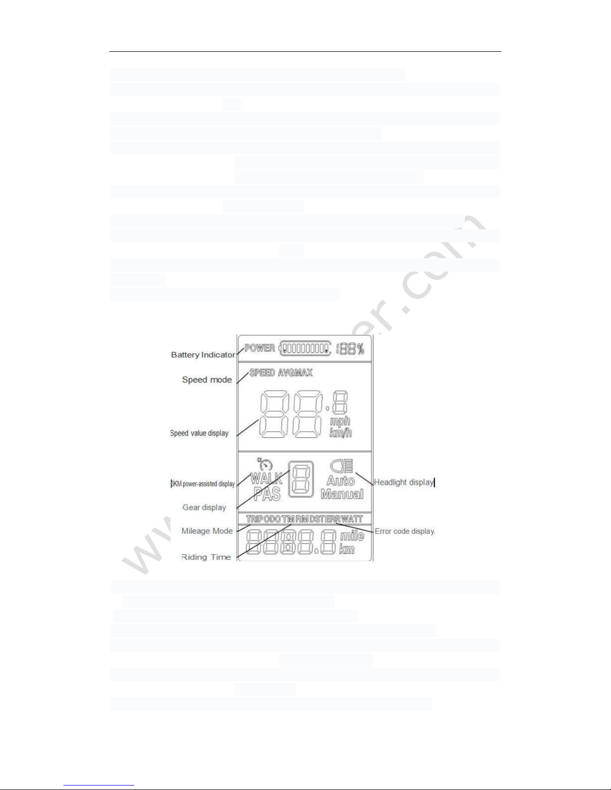
3.Liquid crystal display content and description...........................................................8
1.)Battery Indicator.....................................................................................................8
2.)Speed mode...........................................................................................................9
3.)Speed value display...............................................................................................9
4.)6KM power-assisted display...................................................................................9
5.)Gear display...........................................................................................................9
6.)Headlight display....................................................................................................9
7.)Mileage Mode.........................................................................................................9
8.)Riding Time............................................................................................................9
9.)Error code display..................................................................................................9
4.External key definition.................................................................................................9
5.Instructions for operating methods and functions.......................................................9
1.)Starting up shutdown.............................................................................................9
2.)Speed mode switching.........................................................................................10
3.)Mileage mode, riding time and error code
switching............................................11
4.)Power gear selection............................................................................................12
5.)Headlight switch...................................................................................................13
6.)6KM assistance pushing (Walking pattern)..........................................................13
6.System parameter setting........................................................................................14

www.cyrusher.com
3 / 29
1.)Backlight brightness.............................................................................................15
2.)Metric/Inch system...............................................................................................15
3.)The working voltage meter supported..................................................................16
4.)Sleep time............................................................................................................16
5.)Steering gear........................................................................................................17
6.)Wheel diameter selection.....................................................................................18
7.)Measured number of magnetic steels..................................................................18
8.)Speed adjustment................................................................................................19
9.)Zero start and non-zero boot Settings.................................................................19
10.)Driver setting.......................................................................................................20
11.)Power sensitivity setting......................................................................................21
12.)Power start strength setting.................................................................................21
13.)Booster disk type setting.....................................................................................22
14.)Controller limited value stream setting................................................................23
15.)The controller undervoltage value display...........................................................23
16.)Accumulated mileage resetting............................................................................24
17.)Restore Factory Defaults.....................................................................................24
7.Meter specification parameter................................................................................25
8.Error code definition................................................................................................25
9.Using Tips...............................................................................................................26
10.Common questions and answers..........................................................................27
11.Quality commitment and warranty scope...............................................................27
12.Version changes....................................................................................................27
Introduction
Dear users, for your correct use of LCD - S700 LCD display instrument,please read
the user's manual and relevant notes carefully before using.We will help you to
understand and familiarize the instrument’s functions with the simplest language,
including how to operate the instrument, how to set system parameters, how to
achieve the optimal matching state of motor, controller and instrument and how to
improve the electric control performance of electric motor.The contents of this manual
contain the installation, operation, system parameter setting and proper use of the
instrument, which can help you to solve the problems and doubts in actual use.
1. Outside Drawing and Size Requirements.
1.)Main materials and colors
The material of LCD-S700 instrument shell and external key are mainly ABS,
liquid crystal clear window is Acrylic.
2.)Appearance dimensions and installation dimensions(Unit:mm)

www.cyrusher.com
4 / 29
3.)External key graphics dimensions and installation dimensions(Unit:mm)
4.)Schematic diagram

www.cyrusher.com
5 / 29
Red line: VCC
Blue line: Electric lock DS
Black line: GND
Green line: Data receiving line RX
Yellow line: Data sending line TX
Brown line: Headlight DD
White line: Headlight GND
Note: Specific wiring methods and line colors are customized according to customer
requirements.
5.) Physical installation schematic
Fix the instrument LCD display part and external key to the electric vehicle and
adjust the appropriate angles. Connect the instrumentation plug-in to the controller to the
application plug-in, in the case of bike without power. Turn on the power, the electric bike
and the instrument enter a normal operation condition, thus the instrument installation has
been completed.
2. Product Introduction and Function Overview
1.)The two-way communication protocol and external three-way button facilitate the
operation for customers
2.)Speed display: Including real-time speed, MAX SPEED, AVG SPEED.
3.)Kilometer/mile display: setting the kilometers(K/h) and miles( Mph) according to
customers’ habits.

www.cyrusher.com
6 / 29
4.)Intelligent battery display: display the battery’s current power
5.)Headlight control: control the opening and closing of headlights through external
keys
6.)Backlight brightness three adjustment: set backlighting according to customers’
using habits, 1 grade means-darkest, 3 grade means-lightest.
7.)Five gears control: according to customers’ requirements, you can choose the
assisted gears 0-5 by the outer button, and 0 means neutral
gear, no assistance (The default is 5 gear).
8.)Mileage display: the cumulative mileage can be displayed is 0D0, single mileage
TRIP, riding time.
9.)Fault code prompt: the details is in the error code definitions and schedule 1
10.)6KM power-assisted mode: it displays cruising WALK in the 6KM power-assisted
mode
11.)Parameters setting: all parameters can be set by setting the interface, including
gear, wheel.
3.Liquid crystal display content and description
1.)Battery Indicator: 10 segments energy indicators, can set the voltage values of each
segment according to customers’ requirements.
2.)Speed mode: AVG SPEED, MAX SPEED, SPEED.
3.)Speed value display: Km/h, kilometres per hour, MPH miles per hour
4.)6KM power-assisted display: it displays cruising WALK in the 6KM
power-assisted mode
5.)Gear display: display the current assisted gear, 0-5, and 0 means neutral gear,
no assistance.
6.)Headlight display:it displays when the headlight and backlight is on.

www.cyrusher.com
7 / 29
7.)Mileage Mode :including the single mileage TRIP and the cumulative mileage 0D0,
8.)Riding Time: displays the riding times
9.)Error code display: ERRO and error code are displayed when the fault is detected
4.External key definition.
LCD-S700 adopts the LCD part and external three - to - button separation in the form
of design, the communication is connected by the bottom lead.
There are three keys, using the key replaces “UP”, replaces
“MORE”, replaces “DOWN”.
5.Instructions for operating methods and functions
1.)Starting up shutdown
Long-press the MODE button for 3 seconds when the instrument is off, the instrument
fully shows and starts working, turn on the controller power; In boot state , long press
the button for 3 seconds, the cyclocomputer be power off and close the
controller power supply. If there is no riding or not any operations to the instrument in
10 minutes( set time by the user), the instrument will power off automatically. In the
shutdown state, the power consumption of the instrument and the controller is 0.
The instrument boot display interface is as the image 1 shown.
2)Speed Mode Switch
Long press the button and to change the display information of speed,
show the real-time speed → the max speed → the average speed cyclically.
Display interface of speed mode、riding time are as the image 2,3,4 shown.

www.cyrusher.com
8 / 29
3) Mileage Mode、Riding Time、Error Code switch
Shortly press the button to switch the display of Mileage Mode、Riding Time、Error
Code, show the Trip → ODO → Riding Time → ERR cyclically.
The display interface of switch mode are as the Image 5,6,7,8
shown.

www.cyrusher.com
9 / 29
4) Assistance Stall Chose
Shortly press the button and to switch the assistance stalls, change
the motor assistance power, min stall 1, max stall 5. It is stall 1 by default in boot state, stall 0 is
neutral, which can be seen as the image 9,10
shown.

www.cyrusher.com
10 / 29
5) Headlight Switch
Long press the button for 3 seconds to open the bike light. Long press the
button for 3 seconds again to close the bike light. The headlight display interface are
as the image 11,12 shown.
6) 6KM Assistant Drive (walk mode)
Long press the button for 3 seconds when in bike is in still state, then the ebike
begin assistant drive state, speed presentation is according to the external conditions (Showing

www.cyrusher.com
11 / 29
Figure is 4.5~7.5km/h), showing the symbol of WALK. Release the button (or long
press the button for 3 seconds or shortly press the button ), the
ebike would exit WALK mode. There are two ways of exiting WALK mode, Long press and shortly
press. The specific using method will be according to the customer’s request. As the Image 13
shows.
6. System Parameter Settings
In the boot state, long press the button and , the system
enters parameter setting state(image 14). Under this state, setting the cyclocomputer,
then long press the button and again to exit
the setting state or No Operation(10s) and to exit setting state automatically. In
the parameter setting state, shortly press the button / to
adjust the figure of parameter setting, press the button to switch setting
item and save the parameter figure of the last item.

www.cyrusher.com
12 / 29
1) Back Brightness: Showing P01, shortly press the button
/ to show 1-3,1 is the darkest backlight, 3
is the brightest. 2 is the default state, as the image 14 shows.
2) Metric/Imperial : showing P02, shortly press the button
/ to switch the display of km/h or mph to set
metric/imperial, the default state is km/h, as the image 15,16

www.cyrusher.com
13 / 29
shows.
3) Cyclocomputer Support Voltage: showing P03, shortly press the
button / , shows 24~28,each up step is 12, the
default is 36V, as the image 17 shows.
4) Sleep Time: showing P04,shortly press the button
/ ,and shows 0~60, which indicates the time of

www.cyrusher.com
14 / 29
automatic shutdown when the bike is in still state or there is
no operation.0 presents “won’t automatic shutdown”. The
default sleep time are 5 minutes, as the image 18 shows.
5) Assistance Stall: showing P05, shortly press the button
/ and it displays 0,1,2.
0: the assistant stall is 3-stall mode, which are stall 1,2,3;
1: the assistant stall is 5-stall mode, which are stall
1,2,3,4,5.
2: the assistant stall is 9-stall mode, which are stall
1,2,3,4,5,6,7,8,9.
When the assistant stall is 1, there are 5 stall modes on the
operation interface, as the image 19、20 shows.

www.cyrusher.com
15 / 29
6) Wheel Diameter Choose: showing P06, shortly press the button
/ , switch to
corresponding wheel diameter, the unit
is inch, accuracy: 0.1, as the image 21 shows.
7) Number of Speed Magnet: showing P07, shortly press the button
/ to switch the display range 1-100, as the
image 22 shows.

www.cyrusher.com
16 / 29
Shows the number of measured magnetic steel

www.cyrusher.com
17 / 29
8)Speed adjustment:display P08 short press key /
key to switch display The speed limit range 0 ~
100KM/H, 100 indicates the speed limit, as shown in figure 23
Display speed limit

www.cyrusher.com
18 / 29
9)Zero boot, non-zero boot setting: display P09, short
press key/ key to switch
display 0, 1. 0: zero start, 1: non-zero start, as shown in figure 24
Display startup mode

www.cyrusher.com
19 / 29
10) Drive mode setting: display P10, short press key/
key to switch display 0, 1, 2, as shown in figure 25
0: power driver (which determines how much power the output is through the
power of the help gear, and then turns invalid);
1: electric drive (by turning the driver, the gear is invalid at this time);
2: power drive and electric drive coexist simultaneously (electrically driven zero-start
state is invalid).
Display drive mode

www.cyrusher.com
20 / 29
11) Support sensitivity setting : display P11, short press
key/ key to switch display 1~24. as shown in figure 26
Display the support sensitivity mode
Other manuals for LCD-S700
2
Table of contents
Other Ourmeter Bicycle Accessories manuals