Outland Technology ROV 1000 User manual

Congratulations on the purchase of your OUTLAND ROV!
Outland Technology takes great pride in supplying high quality
underwater video systems.
Your Outland ROV has been rigorously tested. The quality and performance of this
system comes with the full confidence and backing of Outland Technology, Inc. As
a measure of that confidence, your ROV comes with a Limited one-year warranty
that the unit remains free of defects in workmanship and materials.A complete copy
of the warranty statement can be found in the Manual.
This manual covers all ROVs Outland builds. The differences are Frame size,
Thruster size and number of thrusters as well as Console power supply size.
Please familiarize yourself with the entire manual and view the Video before placing
your ROV into service.
Owner’s Record
Record the serial number of your ROV and have it available whenever contacting
Outland Technology regarding this product.
Serial Number: ________________
In addition to the Paper Manual, a USB THUMB DRIVE has been included
containing the following:
1) Photos, (Photos of the complete ROV system).
2) ROV Manual, (Electronic copy of the paper manual)
3) ROV Video, (Complete video on how to hook up and use the ROV)
4) ROV1000.pdf, (Spec/data sheet on the ROV).
5) ROV2000.pdf, (Spec/data sheet on the ROV).
6) ROV2500.pdf, (Spec/data sheet on the ROV).

BLANK PAGE

Contents
LIMITED WARRANTY...................................................................................................................6
ROV General Guidelines..............................................................................................................8
System Overview.........................................................................................................................9
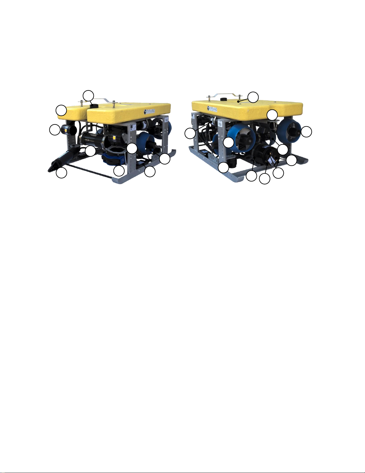
Outland ROV 1000, 2000, and 2500.......................................................................................... 9
Control Console and Power Supply..........................................................................................11
Power Supply: PS-4000 ...........................................................................................................12
Hand Controller........................................................................................................................12
ROV Cable...............................................................................................................................14
System Startup ..........................................................................................................................15
Setup Control Console and Power Supply................................................................................15
Setup ROV...............................................................................................................................16
Prepare for Mission..................................................................................................................16
Video Adjustments ...................................................................................................................16
Perform Preflight Check ...........................................................................................................17
Flight........................................................................................................................................18
Video Overlay Interface.............................................................................................................19
Menu Navigation ......................................................................................................................19
Keyboard Controls................................................................................................................19
Console Menu Switch...........................................................................................................19
Diagnostic Display....................................................................................................................19
Menu Page...............................................................................................................................20
Setup Menu..............................................................................................................................20
Advanced Menu.......................................................................................................................21
Devices Menu ..........................................................................................................................22
System Maintenance .................................................................................................................22
Daily Maintenance....................................................................................................................22
Periodic Maintenance...............................................................................................................22
Electrical Interface.....................................................................................................................23
ROV Control Bottle...................................................................................................................23
Thruster....................................................................................................................................25
UWC-360 Camera....................................................................................................................25
UWL-505 Light, MP-100 Manipulator........................................................................................26
NAV-100 Navigation Bottle.......................................................................................................26
BTL-050 VDSL Bottle (optional) ...............................................................................................27
CON-1050 ROV Control Console.............................................................................................27
ROV Power Supply ..................................................................................................................29
Connector Diagrams ................................................................................................................30
System Drawings.......................................................................................................................31
ROV Block Diagram.................................................................................................................31
ROV Spare Line Routing..........................................................................................................32
ROV Cable Wiring Diagrams....................................................................................................32
Addendum A: Model 300 Thruster (if applicable)
Addendum B: Model 560 Thruster (If applicable)
Addendum C: Model OTI-1080-C, HD recorder.
Addendum D: Model MP-100 Grabber and acc. (If applicable)
Addendum E: Troubleshooting guide.

Outland Technology Inc. 6 46-0002 Rev B1 - April 2021
LIMITED WARRANTY
Outland has a strong commitment to high quality production. Each ROV system has a twelve (12) month
limited warranty against defects in workmanship or materials with the exception of those outlined in the
limitations and exclusions. Outland will repair or replace at its discretion the defective components.
Limitations and Exclusions
•The limited warranty does not cover damage caused by improper use, poor maintenance or
accidental damage of the ROV or its components.
•The limited warranty does not cover items subject to wear including but not limited to view ports,
O-rings, frame, umbilical and propellers unless found to be defective in workmanship and/or
materials.
•The limited warranty does not cover any modification made to the ROV without authorization from
Outland Technology Inc.
•The limited warranty does not cover components damaged due to incorrect power connection per
user’s manual.
Advertising claims made by us represent our honest opinion of the qualities and features offered by the
product described. We disclaim any warranties expressed or implied, including warranties of merchantability
and fitness for a particular purpose, except as provided herein. In no event shall Outland Technology be
liable for consequential damages of any kind.
Shipping
All returns for warranty service must be authorized by Outland. You must call or email Outland for an RMA
number (Returned Materials Authorization). The assigned RMA number must be clearly indicated on each
item returned for service.
NOTE: To submit an ROV or its components for warranty an RMA form must be completed. Please
complete as best and detailed as possible.
For warranty shipping within the first 30 days, Outland will pay for ground shipment on ROV System
domestic orders incoming and outgoing to a maximum of $75.00 each way. International shipments will be
credited up to $75.00 US for incoming and outgoing freight charges to Outland Technology, Inc.
During the first 30 days of the warranty period, should faster delivery service be requested, a $75.00 US
credit towards expedited freight for each applicable leg will be given.
After 30 days the client is solely responsible for shipping to and from Outland Technology Inc.
If you have any questions regarding the installation and operation of this equipment, or if more
information is needed contact:
OUTLAND TECHNOLOGY, INC.
38190 Commercial Ct., Slidell, LOUISIANA USA 70458
985-847-1104 | FAX 985-847-1106
sales@outlandtech.com
www.outlandtech.com

Outland Technology Inc. 7 46-0002 Rev B1 - April 2021
Legend
Safety
Warning
The ROV systems are supplied with 300VDC. Improper use may result in
electrical shock or electrocution. Only trained and experienced personnel
should operate the equipment.
Caution
When propellers are active keep hands, feet and objects away from vehicle.
Caution
NEVER PLUG OR UNPLUG ELECTRONICS WITH POWER ON! Damage or
personal injury may result.
Caution
Do not operate the thrusters in air at high speeds or for extended durations.
Damage to thruster may result.
Warning/
Caution
Hints and Tips
High Voltage

Outland Technology Inc. 8 46-0002 Rev B1 - April 2021
ROV General Guidelines
I. ROV Connecting/ Disconnecting
1.1 Never connect or disconnect any equipment while power is applied to system.
1.2 Turn off power and let sit for 10 seconds prior to disconnecting the umbilical from
the console or ROV. This will allow power inside the console to dissipate.
1.3 Unplug the connectors by holding the body of the connector and not by pulling on
the cable.
1.4 Always use proper dummy plug when connection is not mated to avoid damage
to the unplugged connector.
1.5 Normally devices plugged into the Control bottle do not need to be unplugged
from the bottle. But if situations require device removal, be mindful of the device
mating position when reconnecting. Ensure that the sonar connector and all other
dry mate connectors are clean and dry with no moisture present. Ensure all wet
mate connectors are clean and lubricated with waterproof silicone grease, even
when using a dummy plug.
II. POWER SUPPLY
2.1 Ensure the power connection has a good ground.
2.2 Connect the Green wire to earth ground for added protection.
2.3 If using a generator or Inverter, a minimum of 2,000 watts is necessary for Model
1000 systems and 4,000 watts for the Model 2000 and 2500 systems.
III. ROV DEPLOYMENT
3.1 Be sure to clean and reapply silicon grease (very lightly) on the Umbilical
Connectors.
3.2 When mating umbilical, hold electronics bottle.
3.3 Secure all loose cables inside the ROV. Any loose cables could be pulled into a
propeller, damaging or destroying cable.
3.4 Never activate the Auto Depth or Auto Heading in air.
3.5 When ready to dive, activate Auto-Heading. This will keep the ROV from spinning
on the way down. (Gyro may take a few minutes to stabilize completely)
3.6 Activate auto functions once vehicle is placed in the water.
3.7 Moving the Depth Thumbwheel UP/DOWN in auto-depth will move the ROV in 3
to 4-inch increments.
IV. ROV storage and shipping.
4.1 Clean and flush with fresh water.
4.2 Remove props clean and dry coupling inside and reinstall props.
Port side lateral and port side forward/reverse thrusters are reverse
pitch (left hand).
4.3 Dry the cable and ROV before closing storage boxes. This will minimize mold,
mildew and corrosion on equipment and interior of boxes.
38190 Commercial Court
Slidell, LA U.S.A. 70458
985-847-1104, Fax: 985-847-1106
www.outlandtech.com

Outland Technology Inc. 9 46-0002 Rev B1 - April 2021
System Overview
Outland ROV 1000, 2000, and 2500
The Outland ROV systems are robust, powerful Class II vehicles capable of handling harsh
conditions. System components have been designed for maximum reliability while incorporating
the latest technology. The robust frame allows for additional sensors and equipment to be
mounted and integrated into the vehicle. The tether allows for simultaneous stream of up to 3
analog HD cameras. Options such as 2 function Manipulator and VDSL are also available.
1. Flotation Block
Flotation is closed cell polyurethane Foam with Fiberglass covering. The foam has been
pressure tested to 500 PSI.
2. Front Lights (x2)
There are two UWL-500 with Super Bright LEDs (4,300 lumens 3,000K, 1,440 lux. @1m).
They are set to emit light 220 degrees around the ROV for viewing with any camera selected.
3. Manipulator (optional)
The Outland MP-100 is a two-function magnetically coupled manipulator available as add on
option.
4. Miniature Mechanical Scanning Sonar (optional)
Sonar options are available for addon. Contact Outland for additional information.
5. Front Camera with parallel lasers
The front camera assembly is comprised of two cameras and two lasers. The internal camera
mount is attached to a rotating mechanism resulting in full 360° rotation. The first camera is a
High Definition 1080P color camera. The second camera is a standard definition, 750-line,
0.001 lux sensitivity camera using the latest Ex-view HAD CCD II sensor resulting is 1020 x
508 pixels. Lasers can be powered on and off using the hand controller.
6. Multibeam Sonar (optional)
Sonar options are available for addon. Contact Outland to find out more about available units.
7. ROV Frame
The OUTLAND ROV frames are made of 6061-T6 aluminum. The frame is bead blasted and
protected with anodes. Most components are attached to the frame using aluminum screws
and aluminum nylon lock nuts.
8. Navigation Bottle
The navigation bottle houses the attitude and heading system/ inertial measurement unit
necessary for determining vehicle heading and performing Auto Heading flight mode. The
orientation solution has an accuracy of ±1° in all orientations. The bottle also houses a depth
transducer used for depth reading and performing Auto Depth flight mode. In addition, the
bottle connects and process data from an Altimeter (Auto Depth flight mode) and Cathodic
Protection voltage measurement readings.
9. Thruster (Port Lateral)
Magnetically coupled, DC brushless thrusters are used on all vehicles. The control electronics
are mounted in the motor housing. The propeller rides on composite water bearings. Do not
4
1
2
5
3
6
8
9
7
13
10
11
19
20
17
15
14
16
18
12

Outland Technology Inc. 10 46-0002 Rev B1 - April 2021
operate the thrusters out of water at high speeds or for extended periods of time as damage
may result. (Note: Port lateral thruster standard on the ROV-2500 only)
10. VDSL Bottle (optional)
The VDSL bottle is an optional add on. Typically used with ethernet based sonar units. The
use of the VDSL bottle uses one cable pair in the ROV umbilical. Also requires VDSL
transceiver to be installed in the ROV Console CON-1050.
11. Thruster (Port Fwd/Rev)
Refer to item 9 above.
12. Altimeter (Optional)
Altimeter options are available for addon. Contact Outland to
find out more about available units.
13. Thruster (Vertical)
Refer to item 9 above.
14. ROV Control Bottle
The electronics bottle is responsible for connecting, processing
and communicating data between the ROV and the top side
control. The ROV umbilical (14) connects to the bottle as well as
all thrusters and accessories located on the vehicle. The ROV
connections use female wet mate connectors: 4 pin
Light/Manipulator port (blue), 5 pin HV ports (x6, green), 8 pin
Nav/Sonar port (yellow), and 8 pin Camera port (red).
15. ROV Power & Data Connection
The ROV umbilical connection uses male wet mate 3 pin for power and 8 pin for data.
16. Rear Lights
The electronics bottle houses two 440 lumen LED’s, on the rear face. These lights are
controlled in unison with the front lights.
17. Rear Camera
Rear color camera is included in the ROV Control bottle. It is a standard definition, 750-line,
0.001 lux sensitivity camera using the latest Ex-view HAD CCD II sensor resulting is 1020 x
508 pixels.
18. Thruster (Starboard Lateral)
Refer to item 9 above.
19. Cable grip attachment point
Attached cable grip to this location.
20. Thruster (Starboard Fwd/Rev)
Refer to item 99 above.

Outland Technology Inc. 11 46-0002 Rev B1 - April 2021
Control Console
The ROV Control console (CON-1050) connects the operator to the vehicle and displays ROV
video and data. The control console (CON-1050) houses the monitor (15”, 1700 nit LCD), HD
DVR, video conditioning, signal routing
and connections for the ROV Cable (data
connection), Hand Controller, and auxiliary
controllers in a waterproof case.
1. Control Console (CON-1050)
2. Sun Shield
3. Monitor
4. DVR
5. Power Switch
6. USB keyboard connection
7. Hand Controller Connection
8. Auxiliary Controller Connection
9. Power Supply (PS-1050 or 1080)
10. GFI Trip Indication
11. GFI Test Switch
12. ROV Hand Controller
Power Supply
The power supply provides DC power to
the vehicle and incorporates safety circuits
to keep the operator, divers and the equipment safe in case of a fault. The power supply converts
120/240 VAC (50/60Hz) to floating 300 VDC. The power supply is equipped with Outland’s
Exclusive Line Insulation Monitor (LIM)/Ground-Fault Circuit Interrupter (GFCI). In the event water
leaks into the cable, ROV Control Bottle or thrusters the LIM circuit will trip and protect the
Operator and ROV from any high voltage damage.
PS-1050/PS-1080
Model 1000 ROV’s uses power supply PS-1050. The PS-1050 supplies a max of 1800 watts at
300VDC . When supplying power from a generator or inverter the unit must be capable of
supplying 2000 watts minimum. Any outlet used should be rated at 15-20 amps.
Model 2000 and 2500 ROV’s use power supply PS-1080. The PS-1080 supplies a max of 3600
watts at 300VDC. When supplying power from a generator or inverter the unit must be capable of
supplying 4000 watts minimum. Any outlet used should be rated at 30 amps (120 VAC) to 15
amps (240 VAC).
Monitor Stowed
2
1
4
7
8
5
6
3
9
10
11
12

Outland Technology Inc. 12 46-0002 Rev B1 - April 2021
For full output power to the vehicle, it is recommended to use 240VAC for both PS-1050
and PS-1080 power supplies.
PS-4000
Outlands newest power supply, the PS-4000, is available for all ROV 1000, 2000 and 2500 units.
Supplying up to 4000W at 300VDC, the power supply incorporates the same LIM/GFI and add the
capability of monitoring the output without using the overlay system by means of a small display.
1. High Voltage Power Indicator
Indicates High Voltage Output power is ON
2. GFI Test Switch
Move switch to HV+ or HV- to test fault on each line.
3. Power Supply Display
Indicates system status, voltage, current, high voltage bias, run time and fault history.
•System Status: Indicates Current System Status: “Good” or “Fault” and type of fault.
•Output DC Voltage: Voltage supplied to tether. Measured at topside power supply output.
•Output Current: Tether cable current.
•Output Voltage Bias: Indicates leakage current from high voltage positive to chassis ground
and high voltage negative to chassis ground. HVBias > ±2% indicates potential water leak.
See troubleshooting guide for additional information.
•Run Time: Cumulative run time of power supply.
•Fault History Log: Log of last 8 power cycles, newest results are on the right. A dot indicates
normal operation, + indicates Pos-Side Leak, and –indicates Neg-Side Leak.
3
2
1
System Status
Output Current
Run Time
Fault History Log
Output Voltage Bias
Output DC Voltage

Outland Technology Inc. 13 46-0002 Rev B1 - April 2021
Hand Controller
The Hand Controller is responsible for command, control, and communications.
1. COMM Good LED
Indicates the Hand Controller is communicating with the vehicle. If the light is not
illuminated check Hand Controller and Tether connections. Refer to Troubleshooting guide
for more information.
2. Thruster Enable Button
Press button to enable thrusters. LED will flash for a few moments while each thruster is
tested. LED should stay illuminated indicating the thrusters are working properly.
3. Depth Thumbwheel
Controls vehicle to descend or ascend. In auto depth/altitude mode the control moves the
target depth/altitude set point.
4. Depth Trim Enable
Press button to enable depth trim. LED will illuminate when active.
5. Depth Trim Knob
Add trim current depth set point. Pressing the Depth Trim Enable button will active this
control. Use control to aid in holding vehicle at depth or to drive vehicle at steady speed.
6. Auto Depth/Altitude Enable Button
Press button to enable auto depth/altitude mode. The active mode is selected by the
Altitude/Depth switch. In auto depth/altitude the vehicle will hold vehicle at vertical position.
The Depth Thumbwheel can be used to change the set point up or down.
7. Altitude/Depth Switch
Toggle the switch up or down to choose either altitude or depth hold modes.
8. Auto Heading Enable Button
Press button to enable auto heading mode. LED will illuminate when active.
9. Auto Heading Switch
Toggle switch up and down to choose between Gyroscope and compass auto heading.
10. Horizontal Trim Enable Button
Press button to enable horizontal trim. The LED will illuminate when active.
11. Lateral Trim Knob
Rotate knob counterclockwise to add port lateral trim. Rotate knob clockwise to add
starboard lateral trim.
12. Forward/Reverse Trim Knob
Rotate knob counterclockwise to add reverse trim. Rotate knob clockwise to add forward
trim.
3
4
5
6
7
8
9
10
11
12
2
13
14
1
15
17
16
18

Outland Technology Inc. 14 46-0002 Rev B1 - April 2021
13. Stick Gain Knob
Turn the knob clockwise to increase the maximum stick drive signal to the thrusters from
25-100%. 100% means full power will go to the thruster when the stick control is at 100%.
14. Horizontal Control Joystick
Controls the orientation and movement of the ROV.
15. Camera Control
Use the camera control switch to control movement of the camera. The standard 360
camera will use the up and down portion to rotate clockwise/counterclockwise and the left
right controls to operate the parallel lasers. Hold Right for 1 second to turn the laser on
and hold Left to turn the lasers off. The laser will automatically turn off after one minute.
When the Outland Mini-Pan/Tilt camera is installed and selected the left/right controls are
for pan operation.
16. Camera Select Switch
Press the camera select switch to switch between cameras (up to 3 total). Standard
vehicle is equipped with front and rear camera.
17. Light Control Buttons
Press the Bright (top) button to increase brightness of the ROV front and rear lights. Press
the Dim (bottom) button to decrease the brightness of the ROV lights.
18. Manipulator Control
Controls the open/close and rotation of manipulator.
ROV Cable
The ROV Cable (C-340x) contains one Cat5E cable (four, 24AWG
twisted pair conductors) and twelve 22AWG conductors. Standard
lengths listed below:
C-3405: 500ft (150m)
C-3410,1000ft (300m)
Assembly Drawing on page 31.

Outland Technology Inc. 15 46-0002 Rev B1 - April 2021
System Startup
Setup Control Console and Power Supply
1. Set Control Console and Power Supply units in desired location. Max distance between
units is 4 ft (1.2m).
2. Setup monitor by loosening thumbscrews (1) and pulling out. Un-Fold monitor into desired
position and push carrier back into mount. Place sunshield into desired location.
3. Connect the Keyboard into USB port (2).
4. Connect the Hand controller into HAND CONTROLLER port (3).
5. Connect Aux Controller to AUX Controller port (4) (for use with optional accessories).
6. Connect ground lug to earth ground (5)
7. Connect the grey console connection cable
from the power supply to the control console
(6).
Warning: Once power supply is connected
to input power source, AC voltage is
present on the console connection cable (5)
8. Connect ROV Data cable (8pin) to console (7)
9. Connect ROV Power Cable (3pin) to Power
Supply (8)
10. If using spare lines, refer to Electrical Interface
section for connector pinout (9).
11. Ethernet to VDSL connection (optional) (10).
12. Power connections for DVR and monitor (11).
13. Video Output Connection, typically connected
to DVR (12).
14. Make sure the Main power switch on the
power supply is off.
15. Connect input power to power source (13).
1
7
8
9
6
5
10
11
12
13
2
4
3

Outland Technology Inc. 16 46-0002 Rev B1 - April 2021
Setup ROV
1. Feed the ROV cable (umbilical) through the
pipe (1).
2. Connect cable grip to the ROV using spring
link (2).
3. Apply thin coat of silicon grease to connectors
and plug the connectors into ROV Control
bottle (3).
4. Secure connectors with locking sleeves.
NOTE: Do not over tighten the locking
sleeves, only finger tighten.
Prepare for Mission
1. Ensure thrusters are not obstructed.
2. Apply power to the console. Power indicator will illuminate.
3. Verify COMM Good indicator illuminates. This indicted the Hand Controller is communicating
with the ROV. If indicator does not illuminate refer to Troubleshooting Guide.
4. Verify video and overlay is displayed on the monitor. If the recorder needs setup refer to
Addendum D.
5. If necessary, contact Outland for support with configuring spare lines.
Video Adjustments
The ROV Control Console is equipped with video conditioning hardware which allows the user to
adjust the video signal. The console is setup from the factory for the system cable length. Adding
or removing cable length may require slight
adjustments to the video.
The image to the left shows the Video
Amplifier adjustment section. The red light
indicates power and the green lights indicate
video signal.
If the video signal is too low (no video) or too
high (washed out) or loss of color (long cable
lengths)
Use a small screwdriver to adjust the video.
Use gain to adjust the signal of all channels
and the Length Compensation to adjust the
level per channel. First set the gain then
adjust each channel as needed.
2
3
1
Good Video Signal, Solid green
Low Video Signal, Blinking green
No Video Signal, No light
Gain
Channel Line Length Compensation

Outland Technology Inc. 17 46-0002 Rev B1 - April 2021
Perform Preflight Check
NOTE: When preforming dry testing, limit amount of operating time of the thruster out of
water. The thruster contains bearings requiring water for proper operation. Extended time
or high-speed operations may result in damage to thruster.
1. Test the GFI by moving GFI Test switch towards HV+ or HV-. The HV ON
light will flash indicating the GFI has tripped. Reset by power cycling the
unit. Test the other HV line and verify GFI trips. If test fails, contact
Outland for support.
2. Navigate to the Diagnostic screen and verify HV bias is ≤ 2%. If using PS-
4000 read the bias level off the screen. Greater than 2 indicates a
potential water leak. The last 8 power cycles are logged and displayed
below the HV Bias reading. A dot indicates normal power cycle, + indicates HV+ trip and –
indicates HV- trip.
3. Zero all controls on Hand Controller.
4. Press Enable Thrusters Button
Indicator will blink then remain illuminated indicating thruster are powered.
If Indicator blinks and goes out this indicates an issue. Refer to manual
and troubleshooting guide for details.
Keep hand, feet and objects clear of propellers when power is
applied to vehicle.
5. Test all the controls below:
Press Camera Select to cycle through available standard definition cameras.
Verify video is displayed on monitor. Select the front camera after cycling
through all available cameras.
Move Control joystick in
each direction and verify
associated thruster
activates.
DOWN
UP
Move Depth
Thumbwheel up and
down to verify vertical
thruster activates.
Test forward camera rotate
function (Up/Down). Test
laser operation by holding
Right to turn on and hold
Left to turn off. Test pan if
optional pan and tilt camera
is installed using Right/Left.
RIGHT
LEFT
DOWN
UP

Outland Technology Inc. 18 46-0002 Rev B1 - April 2021
Do not run lights for more than 60s in air.
Flight
When ready to commence mission, enable thrusters. Below is a list of available flight modes. In
any mode manual controls are active.
Flight Modes
Manual
Manual mode passes the pilot inputs directly to the thrusters. All Outland ROV’s default to manual
mode.
Depth Hold
Depth Hold mode holds the vehicle at the set depth. Activate
using the Auto Depth Enable Button and Altitude/Depth toggle
switch to Depth mode. Moving the depth thumbwheel up or
down will increment the depth set point.
Altitude Hold (Optional)
Altitude Hold mode holds the vehicle at the set altitude.
Activate using the Auto Depth Enable Button and
Altitude/Depth toggle switch to Altitude mode. Moving the
depth thumbwheel up or down will increment the altitude set
point. An Altimeter unit is required for Altitude hold.
Heading Hold
Heading hold maintains the heading when enabled. Activate using the Auto Heading Enable
Button. The joystick can be used to adjust the heading to desired heading and release joystick.
The vehicle will maintain the new heading. Auto heading can use either Compass or Gyroscope
sensors. It is recommended to use compass unless flying near magnetic materials.
Trim
Trim is available in each direction.
Stick Gain
Stick gain controls the maximum control stick drive signal from 100% to 25% output. 100% means
full power will go to the thruster when stick control is at 100%.
CW
CCW
OPEN
(ENGAGE CUTTER)
CLOSE
(DISENGAGE CUTTER)
Press Light Bright
Button to turn on ROV
lights.
Press the Light Dim
Button to turn off ROV
lights.
Test Manipulator Open, Close
and Rotate (CCW/CW).
Depth
Altitude

Outland Technology Inc. 19 46-0002 Rev B1 - April 2021
Video Overlay Interface
Outland's Video Overlay system monitors data
communications between the Top Side unit and the
ROV. The interface is used to display system data in
real time and setup the ROV system. There are 9
pages available to input text. The overlay will default
to Text Page 1 and will display the current time, date
and a compass. This view will be superimposed over
video if supplied.
Menu Navigation
There are two ways to navigate the menu system, using a
standard USB keyboard and the Console menu switch (if installed)
located on the console front panel.
Keyboard Controls
?A ? on the screen indicates a high voltage fault has been
detected. Press the ? key to display the fault information. Refer to troubleshooting guide.
Z Devices Menu
Q Display diagnostic data
HDisplay main menu
Esc The escape key will navigate back one menu
Console Menu Switch
Press up or down to display menu
Press up or down again to display selection cursor
Move to desired selection and press right direction (select).
To exit menu press left direction (back)
Diagnostic Display
The system diagnostic display provides the operator with
critical data.
Thruster (Port, Star, etc.): displays control from 0-100%
(max)
When determining the ROV buoyancy, use the
vertical control percent. If the vertical control is
greater or equal to 30% the vertical thruster is
working hard to maintain depth. Adjustments to the
ballast are necessary to minimize the positive buoyancy.
Lamp: Light setpoint from 0-100%
Compass: Direction in degrees from north
Depth: Current ROV depth in selected units
Rating: Depth transducer maximum rating in
PSI
Top Voltage: Topside output voltage
ROV Voltage: Voltage seen at input to the
ROV
Cable: Calculated cable resistance in ohms
Amp: Total ROV Current in amps
Run Time: Total ROV runtime in hours and
minutes
HVBias: measurement of high voltage leakage. Typical value is 0±2%. Any valve greater than 2
indicates a potential leakage in the ROV cable, thruster, or connection between thruster and ROV
control bottle. Any value greater than 30 will trip the GFCI. Below the HVBias is a series of 8 dots.
These indicate the last eight power cycles. A dot indicates normal power cycle. A +indicates a
GFCI trip on the high side and a –indicates a GFCI trip on the low side.
SELECT
BACK
UP
DOWN

Outland Technology Inc. 20 46-0002 Rev B1 - April 2021
Menu Page
The below keys work when displaying text pages.
RReset current page to default, clears all text from current page. A prompt is displayed to
confirm the reset.
EEdit current page text. Add, delete, modify and move text.
SEnter Setup Menu
1-9 Change page, the current page number is displayed
Q Display Diagnostics data.
Z Display list of connected devices. The thrusters will always be displayed, even if not
connected.
When editing a page, a blinking cursor will be shown.
Text will be edited, added or deleted at this point. The
cursor can be moved with the arrow keys and enter
key. The escape key will save edits and exit.
When using the console menu switch use the guide
shown at the bottom of the edit screen. Selecting Options (press button left) will display the Editor
Menu. Pressing left in the Editor Menu screen will exit to main view. When entering text press up
or down to select letter or number and right press (select) to enter next character. To move the
cursor up or down you must go to options, Editor Menu, and select Move Cursor.
Setup Menu
Press the following keys to select the available setup
options.
1. Set the time, date and choose display format
2. Display available font selections. Select number
corresponding to desired font.
3. Displays connected devices firmware number and
revision.
4. Choose the data to display on the text page views
(same for all views) and the position.
Page editing display
4.1. Choose Display Position
4.2. Choose Data to Display
Menu Screen
Other manuals for ROV 1000
3
This manual suits for next models
2
Table of contents
Other Outland Technology Diving Instrument manuals

Outland Technology
Outland Technology ROV 1000 User manual

Outland Technology
Outland Technology ROV 3000 User manual

Outland Technology
Outland Technology ROV 3000 User manual

Outland Technology
Outland Technology ROV 1000 User manual

Outland Technology
Outland Technology 6200 User manual

Outland Technology
Outland Technology ROV 500 User manual

Outland Technology
Outland Technology ROV 1000 User manual

Outland Technology
Outland Technology ROV 500 User manual