Oval LS5076 User manual

Ins. No. S-177
-1
(S-177-1-E)
Ins. No. S-177-1
(S-177-1-E)
機械式計数部付
油用フローペット-NX
50
52
MODEL LS5376
-
2□□A
55
56
OIL SERVICE
FLOWPET-NX
WITH MECHANICAL REGISTER
パルス発信器なし
without pulse generator パルス発信器付
with pulse generator

S-177-1(E)
このたびは、フローペット-NX(NX:New Excellent)をご採用いただきましてありがとうございます。
本製品は、当社において厳重な品質管理の下に製造出荷されております。正しくお使いいただくため、本書では
取り扱いに当たって、必要な注意事項を記載してあります。
ご使用の前にこの取扱説明書をよくお読みいただきますようお願いいたします。
また、本書は大切に保管してください。
1.取り扱い上の注意 ................................................................................................4
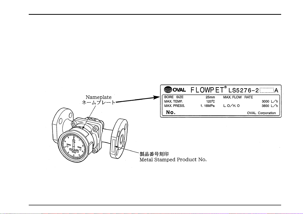
1.1 ネームプレートの確認 ...........................................................................5
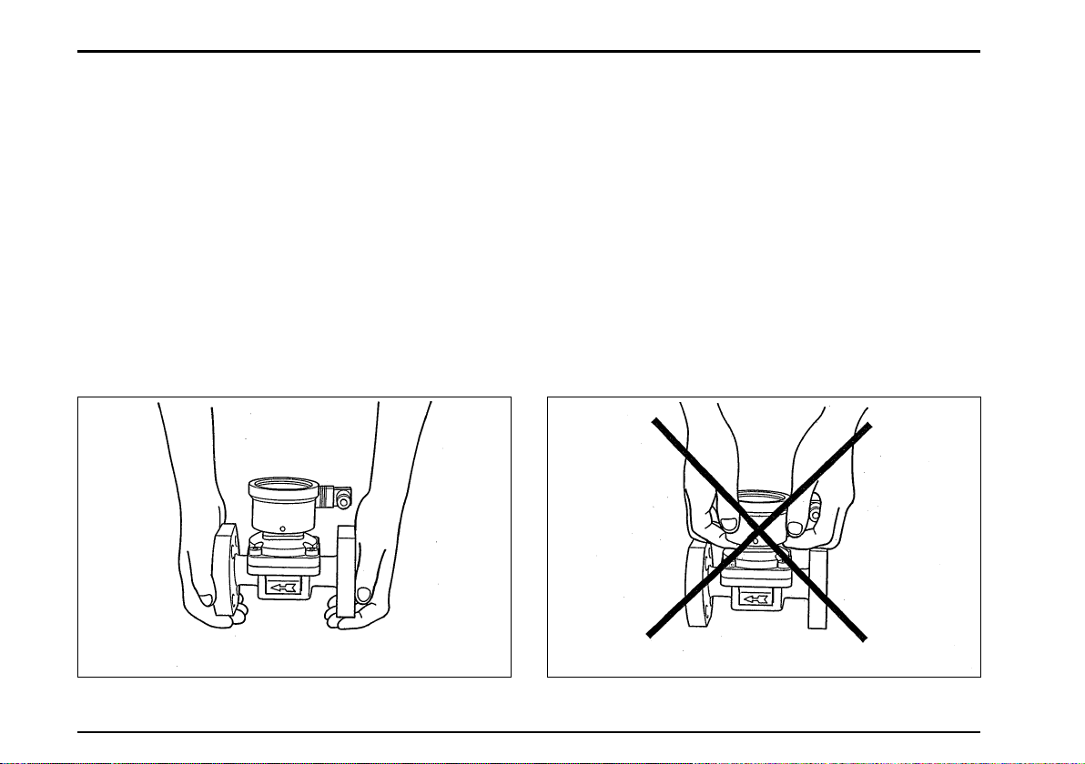
1.2 運搬についての注意事項 ...................................................................... 6
1.3 保管についての注意事項 ...................................................................... 7
1.4 設置場所の注意事項 .................................................................................8
2.使用条件......................................................................................................................9
3.概 要 ...........................................................................................................................9
3.1 製品記号の説明 ..........................................................................................10
3.2 各部の名称 ....................................................................................................11
4.配管要領....................................................................................................................12
4.1 配管上の注意 ...............................................................................................12
4.2 配管をフラッシングする場合 .........................................................15
4.3 保温工事上の注意 ....................................................................................16
4.4 配管例 ...............................................................................................................17
4.5 流入方向の変更方法 ...............................................................................19
5.配線要領....................................................................................................................20
5.1 配 線 .................................................................................................................20
5.2 結線図 ...............................................................................................................21
5.3 結線要領 ..........................................................................................................23
5.3.1 端子説明 .............................................................................................23
5.3.2 端子への結線 ..................................................................................24
6.運 転 ......................................................................................................................27
6.1運転上の注意 ...............................................................................................27
7.故障対策 .................................................................................................................30
8.分解点検要領 ......................................................................................................32
8.1 本体部の分解点検 .................................................................................32
8.2 組立上の注意 ............................................................................................35
9.立体分解図およびサービス部品一覧表 ...........................................36
立体分解図 ............................................................................................................36
サービ部品一覧表............................................................................................37
10.標準仕様.................................................................................................................38
10.1 流量範囲 .....................................................................................................38
10.2 本体部 ...........................................................................................................38
10.3 計数部、発信器 .....................................................................................40
11.外形寸法図 ...........................................................................................................44
11.1 フローペット-NX .................................................................................44
11.2 ストレーナ ................................................................................................45
目 次

S-177-1(E)
Thank you for choosing OVAL's Flowpet-NX (NX for New Excellent).
All our products are manufactured, tested, and shipped from our factory under rigorous quality control.
This manual is designed to assist the user to obtain the best performace of this product throughout its
service life. In order to take sufficient care, please read this instruction carefully before the use and keep it
handy for quick reference.
1. HANDLING PRECAUTIONS ................................................4
1.1 Confirming the Nameplate ..............................................5
1.2 Transportation Precautions ............................................6
1.3 Storage Precautions ..............................................................7
1.4 Installation Location Precautions.................................8
2. OPERATING CONDITIONS ..................................................9
3. GENERAL DESCRIPTION ......................................................9
3.1 Product Code Explanation ............................................10
3.2 Part Names ...............................................................................11
4. PIPING...................................................................................................12
4.1 Piping Precautions ..............................................................12
4.2 Flushing the Piping Assembly ..................................15
4.3 Lagging Work Precautions ...........................................16
4.4 Examples of Installation..................................................17
4.5 How to Change the Flow Directions ....................19
5. WIRING ................................................................................................20
5.1 Field Wiring .............................................................................20
5.2 Wiring Diagrams ..................................................................21
5.3 Wiring Connections ............................................................23
5.3.1 Terminal Identification .....................................23
5.3.2 Connections to Terminals .................................24
6. OPERATION ................................................................................27
6.1 Note on Operation ............................................................27
7. TROUBLESHOOTING ..........................................................31
8. DISASSEMBLY AND INSPECTION ........................32
8.1 Meter Body Disassembly and Inspection ......32
8.2 Precautions at Assembly ............................................35
9. EXPLODED VIEW AND
SERVICE PARTS LIST .......................36
Exploded View .............................................................................36
Service Parts List .......................................................................37
10. GENERAL SPECIFICATIONS .......................................39
10.1 Flow Range .........................................................................39
10.2 Basic Meter .........................................................................39
10.3 Register, Pulse Generator ........................................40
11. OUTLINE DIMENSIONS ....................................................44
11.1 Flowpet-NX .........................................................................44
11.2 Strainer ...................................................................................45
CONTENTS

S-177-1(E)
1.取扱い上の注意
本器は工場で十分な検査をして出荷されております。
本器がお手もとへ届きましたら、外観をチェックして、
損傷の無いことをご確認ください。
本項では取扱いに当って必要な注意事項を記載して
ありますのでまず本項を良く読んでください。
本項記載以外の事項につきましては関係する項目を
ご参照ください。
お問い合わせ事項が生じましたら、お買い求め先あ
るいは最寄の当社サービス網にご連絡ください。
1. HANDLING PRECAUTIONS
Every Flowpet is thoroughly tested and inspected
before shipment from our factory. When received,
inspect the appearance of the product and make
sure that there is no damage incurred by rough
handling during transit. First of all, thoroughly read
the handling precautions described in this section.
For topics other than those stated in this section,
refer to respective sections. If at any time in the
future you seek our assistance, contact the nearest
sales office in your area.

Nameplate
ネームプレート
製品番号刻印
Metal Stamped Product No.
S-177-1(E)
KEROSENE
S-177-1(E)
1.1 ネームプレートの確認
フローペットは、1台づつ仕様に合わせ出荷されて
おります。
計数部上面のネームプレートに製品番号および定格
仕様が記載されています。10頁の製品番号および38頁
の標準仕様を対応させて、ご注文の仕様どおりである
ことをご確認ください。
1.1 Confirming the Nameplate
The Flowpet is adjusted to individual specifications
before shipment from our factory. Indicated on
the register nameplate are the product code
number and ratings. Make sure that the Product
Code Explanation in page 10 and the General
Specifications in page 39 conform to your particular
specifications.
◆お問い合わせの際は、製品名称、製品記号(MODEL)、
製品番号、定格仕様などをご連絡ください。
◆When you inquire, specify the product name,
model number, serial number, ratings/specifications
and other information.

S-177-1(E)
S-177-1(E)
S-177-1(E)
1.2 運搬についての注意事項
(1)運搬中の事故により損傷することを防ぐためフロー
ペットはなるべく当社から出荷したときの包装状
態で設置場所まで運んでください。
(2)本器は、本体部-計数部-発信器の全てを一体と
して調整・検査されております。
従って、必ず一体として取り扱い、計数部を分離
したりしないでください。
(3)運搬中、計数部に強い衝撃を与えないようにして
ください。
1.2 Transportation Precautions
(1) In order to safeguard against damage during
transportation, transport your Flowpet to the
installation location in the style packaged from
our factory if possible.
(2) This instrument is adjusted and inspected as
an assembly consisting of the flowmeter, pulse
generator and register. It should therefore be
handled as an assembly at all times; you should
not attempt to separate the register.
(3) During transit, exercise care not to give impact
shocks to the register.
〈良い例〉〈Hold like this〉 〈悪い例〉〈Don't hold like this〉

S-177-1(E)
7
1.3 保管についての注意事項
フローペットがお手もとへ届いた後、設置までの期
間が長いと、思いがけぬことから故障が生じることが
考えられます。あらかじめ長時間の保管が予想される
場合は、以下の項目にご注意ください。
(1)フローペットは、なるべく当社から出荷した時の
包装状態のまま保管してください。
(2)保管場所は、下記の条件を満足する所を選定して
ください。
☆雨や水のかからぬ場所。
☆振動や衝撃の少ない場所。
☆保管場所の温度や湿度が、できるだけ常温常湿
(25℃、65%程度)である場所。
(3)一度使用したフローペットを保管する場合、流量
計継手、管路およびケース外観などに測定流体が
付着していることのないように、清浄なエアー、
N2ガスなどでパージしておいてください。
(4)計数部はシンナー、アルコールなど有機溶剤をか
けないように注意してください。
(5)計数部を分解して、改造しないでください。
(改造した場合は、保証できません。)
1.3 Storage Precautions
If the Flowpet is to be stored over an extended
period of time before installation, make sure to take
following precautions to avoid unexpected damages:
(1) The Flowpet should be stored in the style
packaged in our factory if circumstances permit.
(2) Select a storage location that meets the fol-
lowing requirements:
☆ Where it is free from rain and water.
☆ Where vibration and impact shocks are least
encountered.
☆ Where temperature and humidity in the
storage location are as near to the room
temperature and humidity (25℃ and 65% or
so).
(3) If you store a Flowpet which has been placed
in service for any length of time, it should be
purged with clean air or N2 gas, etc. to keep
the metered material from adhering to the
flowmeter couplings, pipeline, housing, etc.
(4) Do not attempt to apply thinner, alcohol or other
organic solvent to the register. If dirt sticks and
it is difficult to remove, use neutral detergent.
(5) Do not attempt to disassemble the register
and modify in any way. (We cannot guarantee
performance of modified Flowpet.)

S-177-1(E)
1.4 設置場所の注意事項
(1)保温工事を施す場合、計数部、ストレーナ蓋、ド
レン抜きプラグは、保温しないでください。なお、
流量計は、配管より容易に分離できるよう考慮し
てください。
(2)本計数部の使用周囲温度は-10 ~+ 60℃です。
直射日光および反射熱などによって、計数部が高
温にさらされる危険性がある場合には日除けなど
を設け、屋外使用には露除けを設置し、仕様温度
範囲内でご使用頂くようお願い致します。
1.4 Installation Location Precautions
(1) When lagging is necessary, the register, strainer
cover and drain plug should not be lagged,
however. Also, make sure that the meter can be
separated readily from the piping assembly.
(2) This register operates at temperatures between
-10 to +60℃. If exposure to elevated tem-
perature is expected by the direct sunlight,
reflected heat, etc., protect the register with a
sunshade or heat shield to ensure its operation
is maintained within the specified temperature
range.
〈注意〉配管および運転に当たっては、必ず本
取扱説明書を十分読んでから作業を行
ってください。
配管要領…………12頁
運転上の注意……27頁
IMPORTANT: Read this instruction manual
thoroughly before you start working on piping
and initiate operation. See page 12 for piping
instructions and page 27 for operating instruc-
tions.

S-177-1(E)
2. 使用条件
この流量計は高い精度と寿命を保つため流量、圧力、
温度、粘度について指定された条件で使用される必要
があります。
この使用条件は流量計計数部および本取扱説明書38
頁の標準仕様に記載されています。
取り付け、運転前によくお読みください。
2. OPERATING CONDITIONS
To maintain the high accuracy and long life of
this meter, it is necessary that the meter be used
within the specified conditions in flowrate, pressure,
temperature and viscosity. These operating
conditions are stated on the flowmeter's register
and in the general specifications on page 39 of
this instruction manual. Read these instructions
throughly before installation and operation.
3. 概要
(1)オーバル流量計本来の高い精度を発揮し、正確な
流量計測が可能です。
(2)直読積算計数部は、シンプルなデザインで、機能
本位に徹底した明るく見やすい設計となっています。
(3)接液部品が少なく、耐久性に優れています。
(4)流量出力信号により各種の遠隔計測用受信器と結
合し、制御・調節・記録などが容易にできます。
3. GENERAL DESCRIPTION
(1) Precise flow measurement can be achieved by
nature of the Oval positive displacement meter.
(2) Direct-readout type counter is specifically
designed for function and legibility first.
(3) Minimum wetted parts count contributes to long
service life.
(4) Output signal for flowrate information can be
used, when combined with a remotely located
receiving instrument, to control, regulate or
record processes.

S-177-1(E)
10
3.1 製品番号の説明
この取扱説明書は次の製品組み合わせについて記載
されています。
3.1 Product Code Explanation
In this instruction manual, the following combi-
nations of products are described.
製品形式 Code 説 明 Description
①②③④⑤⑥-⑦⑧⑨⑩
機種 Model L S 専用オーバル流量計 Dedicated Oval Flowmeter
容量形式
Meter Size
5 0 20A JIS 10K RF
5 2 25A JIS 10K RF
5 3 40A JIS 10K RF
5 5 40A JIS 10K RF
5 6 50A JIS 10K RF
機種名 Model Name 7 フローペット-NX Flowpet-NX
用途区分 Application 6 -油用 Oil Service
機械式計数部 Mechanical Register 2 常に“2” Always“2”
読取単位 Readout Units 1リットル(L) Liters (L)
2ガロン(オプション) Gallons (Option)
発信器 Pulse Generator
0発信器無し(標準) Eliminated (Standard)
1オープンコレクタパルス発信器付
補正パルス 10P/REV(オプション)
Open collector pulse provided
Factored pulse 10P/REV (Option)
2電圧パルス発信器付
補正パルス 10P/REV(オプション)
Voltage pulse provided
Factored pulse 10P/REV (Option)
3接点パルス発信器付
補正パルス 1P/REV(オプション)
Contact pulse provided
Factored pulse 1P/REV (Option)
その他 Others A 常に“A” Always“A”

S-177-1(E)
11
S-177-1(E)
11
3.2 各部の名称
Part Names
累積積算計ドラム(6桁)
TOTAL COUNTER
DRUM(6 digits)
流入方向矢印
FLOW DIRECTION ARROW
本体部
METER BODY
指 針
機械式計数部
MECHANICAL
REGISTER
接続フランジ
FLANGE
〈パルス発信器なし〉
without pulse generator
〈パルス発信器付〉
with pulse generator
発信器
PULSE
GENERATOR ケーブルコネクタ
CABLE CONNECTOR
POINTER

S-177-1(E)
1
4. 配管要領
4.1 配管上の注意
(1)配管歪みを与えないようフランジボルトを無理に
締め付けないように取り付けてください。
(2)流量計はポンプの出口側に取り付けてください。
(3)ストレーナを流量計の上流側に設置してください。
なお、ストレーナのネットは定期的に洗浄する必
要があります。
(4)配管系全体の圧力損失を考慮してポンプを設けて
ください。なお、ポンプを使わず落差(ヘッド)
によって流す場合は、配管系・フローペット・ス
トレーナなどの圧力損失より大きな圧力(ヘッド)
を与えてください。
最大流量時の圧力損失は次頁の表の通りです。
4. PIPING
4.1 Piping Precautions
(1) Install the meter, exercising care to avoid pipe
strains.
(2) The meter should be installed downstream of the
pump.
(3) Provide a strainer upstream of the meter.
Strainer net should be cleaned on a regular
basis.
(4) Install the pump with careful consideration of
the pressure loss of the entire piping system.
When the fluid is able to flow with head of the
fluid without a pump, make sure that the head
is greater than the pressure loss of the piping
system, Flowpet, strainer, etc.
Pressure losses at the maximum flowrate are
shown on next page.

S-177-1(E)
13
形 式
Model
圧 力 損 失 kPa
Press. Loss
灯 油 1.2 mPa・s
Kerosene
重 油 19 mPa・s
Heavy Oil
LS5076 14(1600L/h) 40(2000L/h)
LS5276 13(3000L/h) 56(3800L/h)
LS5376 13(5m3/h) 30(6.4m3/h)
LS5576 25(11m3/h) 54(14m3/h)
LS5676 27(20m3/h) 55(24m3/h)
形 式
Model
圧 力 損 失 kPa
Press. Loss
灯 油 1.2 mPa・s
Kerosene
重 油 19 mPa・s
Heavy Oil
SS5278A 6(3000L/h) 50(3800L/h)
SS5378A 7(5m3/h) 28(6.4m3/h)
SS5578A 23(11m3/h) 26(14m3/h)
SS5678A 25(20m3/h) 40(24m3/h)
●フローペットの圧力損失 Pressure Losses of Flowpet
●ストレーナの圧力損失 Strainer Pressure Losses
〈油 用〉〈Oil Service〉
ストレーナ
Strainer
ストレーナ
Strainer
S-177-1(E)
1
●フローペットの圧力損失 Pressure Losses of Flowpet
〈油用〉〈Oil Service〉
形 式
Model
圧 力 損 失 kPa
Press. Loss
灯 油 1.2mPa・s
Kerosene
重 油 19mPa・s
Heavy Oil
LS5076 14(1600L/h) 40(2000L/h)
LS5276 13(3000L/h) 56(3800L/h)
LS5376 13(5m3/h) 30(6.4m3/h)
LS5576 25(11m3/h) 54(14m3/h)
LS5676 27(20m3/h) 55(24m3/h)
●ストレーナの圧力損失 Strainer Pressure Losses
形 式
Model
圧 力 損 失 kPa
Press. Loss
灯 油 1.2mPa・s
Kerosene
重 油 19mPa・s
Heavy Oil
SS5278A 6(3000L/h) 50(3800L/h)
SS5378A 7(5m3/h) 28(6.4m3/h)
SS5578A 23(11m3/h) 26(14m3/h)
SS5678A 25(20m3/h) 40(24m3/h)

S-177-1(E)
1
(5)流量計本体の矢印に従って、流入方向を正しく合
わせてください。
(6)この流量計の発信部は磁束密度の変化を利用して
います。
できるだけ外部磁束の影響を除くため、強磁石お
よび強磁界を発生する導線から離した場所に、設
置してください。
(7)電気加温をする場合は、当社までご相談ください。
(8)配管の気密試験を実施する際は、空気の暴走によ
る回転子破損を防止するため、慎重なバルブ操作
が必要です。
23~25頁の操作方法に従って、注意して行ってく
ださい。
(5) Align the flow direction with the arrow mark on
the meter body.
(6) The pulse generator of this meter makes use
of the changes in magnetic flux. To minimize
the influence of external magnetic fields, select
an installation location sufficiently away from
powerful magnets and conductors creating
strong magnetic fields.
(7) If electric heating is desired, consult OVAL.
(8) When you conduct a gastight test on the existing
piping assembly, careful valve operations
sequence is required to safeguard the rotors
against damage due to violent rotor spinning by
rushing air currents. Adhered to the instructions
on operations sequence described on page 23 to
25.

流入方向
FLOWDIRECTION
ストレーナ
STRAINER
バイパスライン
BYPASSLINE
バルブ
VALVE
短管
SHORTPIPE
S-177-1(E)
1
4.2 配管をフラッシングする場合
◆必ず配管から流量計を取り外し、短管を挿入して行
ってください。
流量計を取り付けた状態でフラッシングを実施しま
すと、計量室に重大な損傷を生じます。必ず、流量計
を取り外してから行ってください。
4.2 Flushing the Piping Assembly
◆Be sure to remove the meter from the piping
assembly and install a short pipe section in
place of the meter.
Flushing the piping assembly with the meter in
place will result in serious and costly damage to the
meter's measuring chamber.

S-177-1(E)
1
4.3 保温工事上の注意 4.3 Lagging Work Precautions
寒冷地で使用し凍結の心配のある場
合、凝固性の液体を計量する場合な
どは、流量計・ストレーナの保温工
事を行うことをおすすめします。
For applications where the meter is to be
placed in service in cold regions or where
solidifying materials are to be metered,
lagging work for the flowmeter and
strainer is recommended.
(1)保温材を覆う前に必ず液漏れがないか点検してく
ださい。
(2)流量計の保温は分解点検などが容易に行なえるよ
う配慮してください。
(3)ストレーナは上蓋が容易に取り外せるよう保温被
覆してください。なお、ストレーナのネットは定
期的に洗浄する必要があります。
(4)計数部・発信器は絶対に保温しないでください。
もし保温しますと過大な温度が加わり事故の原因
になります。
(1) Be sure to inspect for liquid leaks before cov-
ering with lagging.
(2) Take into consideration simple and readily
disassembly and inspection for the lagging of the
meter.
(3) Strainer should be lagged for quick top cover
removal. Strainer net should be cleaned on a
regular basis.
(4) Register and pulse generator must not be
lagged. If they are lagged, temperature will
rise to an excessive level and result in costly
damage.

S-177-1(E)
17
S-177-1(E)
17
S-177-1(E)
17
4.4 配 管 例 Examples of Installation
(注記)⇨12頁の“配管上の注意”に従って配管してください。
⇨外形寸法図は44頁参照
NOTE: Make pipe connections following the instructions
under the topic " Piping Precautions" on page 12.
For outline dimensions, see page 44.
〈垂直配管〉
配管上部より落下するスケールを防ぐた
め、バイパス側に取り付けてください。
●Vertical Line
Install on the bypass side to prevent
scales falling from top of the piping
assembly.
〈水平配管〉……標準配管
●Horizontal Line……Standard piping
※印…分解点検の際必要なスペースとして600mm以上あけてください。
Marked ※ is the space required for disassembly and inspection.
Secure at least 600mm.
ストレーナ
STRAINER
バイパス管
BYPASS
フローペット-NX
FLOWPET-NX
ドレン抜き
DRAIN VALVE
IN
OUT
OUT
IN
ストレーナ
STRAINER
フローペット-NX
FLOWPET-NX

S-177-1(E)
18
S-177-1(E)
1
〈誤った配管例〉 ●Example of Incorrect Piping
◎下図のような流量計の取り付け方をしないよう注意してください。
(計量室が水平に設置されるのが正しい取り付け方です。)
Do not install the meter in a position like the diagram below.
(Installation is correct if the measuring chamber is on a level
plane.)
⇨ 流入方向の変更方法は19頁参照
⇨ 発信器付の場合は20頁の配線要領に従って結線してください。
⇨ To change flow directions, see page 19.
⇨ If your meter is equipped with a pulse generator, make electrical connections according to the wiring
instructions on page 20.
フローペット-NX
FLOWPET-NX
IN
OUT
ストレーナ
STRAINER
バイパス管
BYPASS
誤り
WRONG

S-177-1(E)
19
S-177-1(E)
19
S-177-1(E)
19
S-177-1(E)
1
4.5 流入方向の変更方法
● 出荷時のフローペットの流入方向は右から左に組
み付けられています。変更する場合は次の方法で
容易に変更可能です。
4.5 How to Change the Flow Directions
● The Flowpet is so assembled to accept the flow
from right to left. Flow directions can simply and
readily be changed in the following manner:
① 流量計をパイプラインより外してく
ださい。流入方向が右→左であった
ものを左→右に変える場合は、まず
計数部のねじ4本を外します。
② 計数部を180°回転させてから、再び
計数部を取り付けてください。
〈注意〉
回転する際、計数部から内器を引き抜
かないでください
③ 図のように本体を反転させ、再びパ
イプラインに取り付けてください。
左→右であったものを上→下、下→
上にする場合も同様に行なってくだ
さい。
① Remove the flowmeter from the
pipeline. In case of changing the
flow direction from R-to-L to
L-to-R. first of all take off four
screws on the register.
② Turn the register 180°.
Then, reinstall the register.
CAUTION:
Do not draw the internal assembly
out of the register while you rotate
the assembly.
③ Turn the meter body as shown
in the figure and reinstall in the
pipeline. The same applies to
changing the directions from
L-to-R to Top-to-Bottom or
Bottom-to-Top.
矢印(⇦)
ARROW MARK
計数部を180°回転させる。
Turn the register 180°.
計数部
REGISTER
OUT IN
IN OUT

S-177-1(E)
0
5. 配線要領
パルス発信器付MODEL LS □ □ 76-2 □ □ Aの場
合は、次の要領で配線をしてください。
また、配線に当たっては、受信器の取扱説明書(配
線欄)を参照してください。
5.1 配線
(1)配線用ケーブル
配線ケーブルは、特に指定のない限り、次のもの
を使用してください。
シールド付クロロプレンキャブタイヤケーブル
〔2種〕(JIS-C3311)、またはシールド付ビニル
キャブタイヤケーブル〔2種〕(JIS-C3312)、導
体断面積0.5mm2~1.5mm2、心数は用途に合わせ
て2~3心をご使用ください。
(2)伝送距離
伝送ケーブル(JIS-C3311、C3312 導体断面積:
1.5mm2)を使用した場合の伝送距離は1㎞以下
が標準です。
(注記)1㎞を越える場合は、当社へご連絡ください。
(3)誘導障害の防止
配線は、誘導障害を起こさぬよう、他の強電用ケ
ーブルまたは、強電回路から離して配線するよう
に注意してください。
5. WIRING
In case of the pulse generator equipped Model LS
□□ 76- 2 □□A, make electrical connections as
follows. Also refer to the instruction manual for
the receiving instrument (topic under "Wiring
Instructions") to be used.
5.1 Field Wiring
(1) Field wiring cables
Use the following cables unless otherwise
specified:
Shielded chloroprene cabtyre cables (Kind 2) (JIS
C3311) or shielded vinyl cabtyre cables (Kind
2) (JIS C3312) with a sectional area 0.5mm2 to
1.5mm2. Use 2 to 3 conductor cables according to
your particular application.
(2) Transmission length
With transmission cables (JIS C3311 or C3312
having a conductor area of 1.5mm2), the maxi-
mum transmission length is one kilometer.
NOTE: If transmission length exceeds one
kilometer, consult us.
(3) Prevention of inductive interference
Route the field wiring sufficiently away from
existing power cables or power circuits, to
minimize possible stray current pickup.
This manual suits for next models
4
Table of contents
Other Oval Industrial Equipment manuals
Popular Industrial Equipment manuals by other brands

Jäger
Jäger Z33-M060.10 K2S15 manual

ABB
ABB HT612326 Operation manual

ABB
ABB HT843151 Operation manual

Thermo Scientific
Thermo Scientific NESLAB System IV Instruction and operation manual

Emerson
Emerson B302 Installation, operation and maintenance instructions

acrison
acrison 105 Series Operating and instruction manual

Global Industrial
Global Industrial 168110 instruction manual

Tyco Electronics
Tyco Electronics EPP-0001-INT-4/10 installation instructions

JST
JST MKS-L instruction manual

IEMCA
IEMCA MASTER 880-VERSO P Manual for use and maintenance

Emerson
Emerson Fisher 3024C instruction manual

Rondo
Rondo Econom Series operating manual