OVE MICAH 6701001 User manual

PAGE 1
A general installation guide is provided in the YouTube link below
or through scanning the QR code below.
https://tinyurl.com/5xk4z3ms
MICAH TANKLESS SMART TOILET
INSTALLATION MANUAL
SKU : 6701001
MODEL : MICAH
Flush
1.28 gpf | 4.8 lpf 6”
18 7/8”
ø3 9/16” ø2 1/16”
27 3/4”
5 15/16”
21 1/4”
18 3/16”
11 7/16”
15 3/8”
15 3/8”
10”
14 15/16”
6 5/16”
10 1/4”
12”
10 13/16”
32”
32”
27 3/8”
27 3/8”
2x ø5/8”
11 5/8”
11 7/16”
Questions, problems, need help?
Before returning to your retailer, call our customer service department at :
1-866-839-2888
8 a.m. - 5 p.m., EST, Monday - Friday
17”

PAGE 2
TABLE OF CONTENTS
TABLE OF CONTENTS ......................................2
SAFETY INFORMATION ....................................3
POWER OUTLET................................................3
PARTS LIST........................................................4
TOOLS REQUIRED (not supplied) ...................4
INSTALLATION...................................................7
INSTALLATION OPTION#1: FOR INSTALLA-
TION TO A 1/2” WATER OUTLET PIPE...........10
INSTALLATION OPTION#2: FOR INSTALLA-
TION TO A 3/8” SHUT-OFF VALVE..................13
BATTERY USAGE SAFETY GUIDELINES ......16
BATTERY INSTALLATION ...............................16
FIRST TIME USE GUIDELINES .......................18
REMOTE CONTROL PAIRING.........................19
TOILET SEAT KEYPAD DESCRIPTION ..........20
REMOTE CONTROL BUTTON DESCRIPTIONS
21
AUDIO SIGNALS..............................................23
FEATURES .......................................................24
CLEANING THE SHUT-OFF VALVE WATER
FILTER ..............................................................25
CLEANINGTHEBUSHING FILTER...................26
LONG TERM STORAGE ..................................27
BATTERY MAINTENANCE ..............................27
SPECIFICATION SHEET ..................................28
FCC STATEMENT.............................................29
MAINTENANCE AND CARE ............................30
LIMITED PRODUCT WARRANTY....................30

PAGE 3
CAUTION
1.Do not disassemble toilet by yourself.
2.Ensure that there is proper air ow in the room to avoid humidity buildups.
3.Ensure that the product is set more than 0.6 meter away from the bathtub.
4.Ensure electric power is AC 120V.
5.Ensure the electrical socket can bare a load of 1800W power (or else it can cause re or electrical shock).
6.Ensure the electrical source is well grounded.
7.Do not put any water or detergent on the product or its electrical plug.
8.Do not touch the electrical plug with a wet hand (or else it can cause re or electric shock).
9.Do not use the product if it has these following problems, and if the problem occur, turn o the electricity and water shut-o valve
immediately:
• Water leaking from the pipe or the main body.
• Crack or breakage
• Abnormal sound or smell of the product
• Smoke coming out from the product
10. Keep any ame or ammable products away from the toilet.
11. Do not step on the toilet seat, the seat cover, the ceramic body, or put anything heavy on the product. Otherwise, the product may
break and may cause injury or the product may break and may cause indoor ooding.
12. Do not put your nger or anything else into the outlet of the drying blower.
13. Do not touch or cover the drying blower outlet with clothes, or it may lead to burn injury or electric shock.
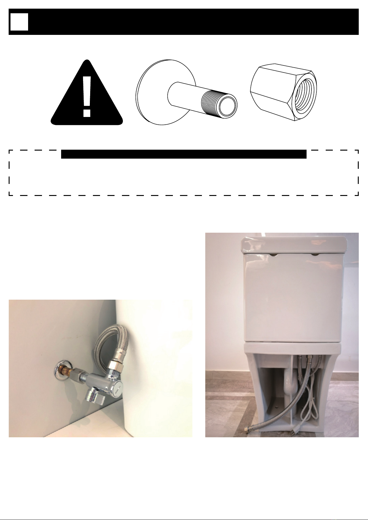
14. Do not tightly bend or press the exible supply hose, or it may lead to water leakage or it may decrease the water pressure.
15. Always clean the product with soft cleaning products.
16. Do not use any harsh detergents to clean the product.
17. Do not throw anything other than toilet paper into the toilet or it may lead to blockage and indoor ooding.
18. Do not ush objects like a comb, toothbrush or other sanitary product.
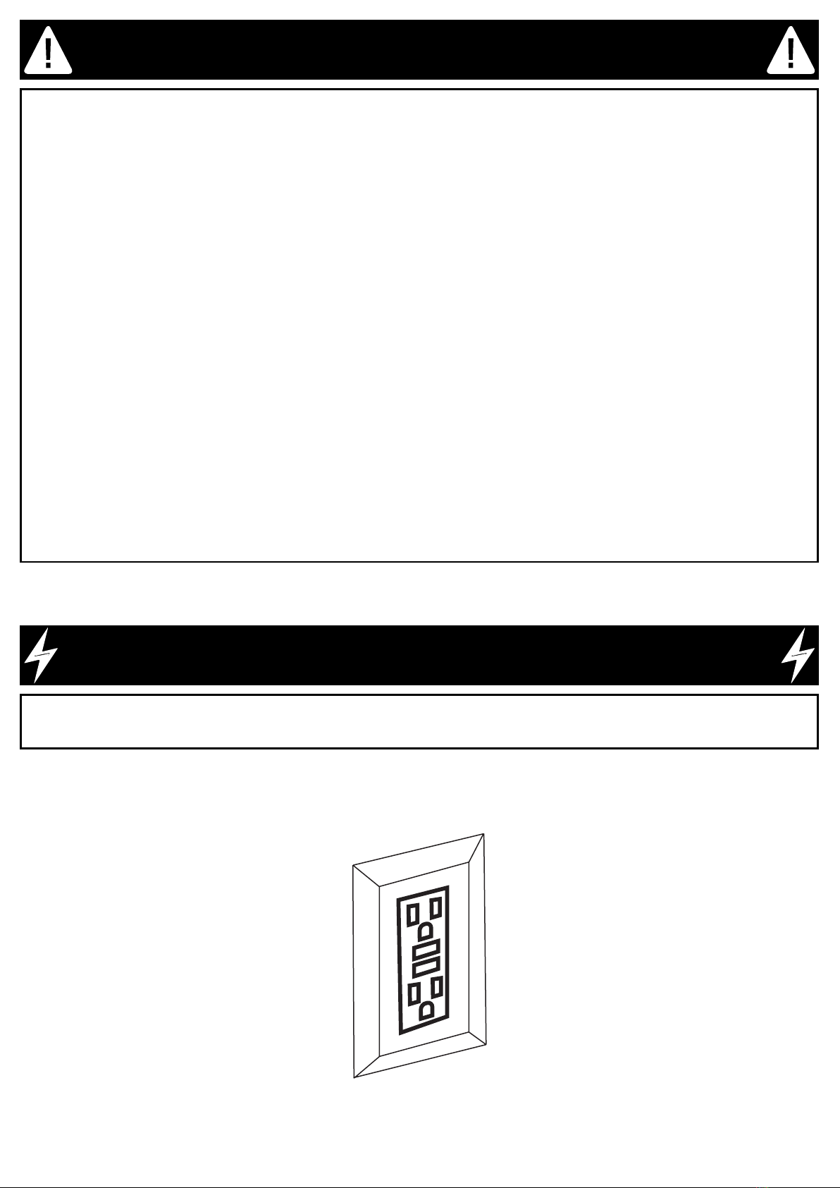
SAFETY INFORMATION
POWER OUTLET - GFCI
POWER OUTLET REQUIREMENT
This product must be plugged into a working GFCI power outlet to avoid potential damages on the electronic component during electrical
surges. The power outlet must have a dedicated minimum 1800W capacity for the smart toilet.
GFCI
SOCKET

PAGE 4
PARTS LIST
D
A
E
C
F
J
N
L
K
M
O
B
P
RSTUV
G
I
H
Q
W
X
TOOLS REQUIRED (not supplied)
Screwdriver Measuring Tape Adjustable wrench Silicone

PAGE 5
PARTS LIST
ITEM # DESCRIPTION QUANTITY PART CODE
AToilet Tank Cover 1 99TOI0546-OU
BInner Tank Shelf 1 99TOI0369-OU
CToilet Tank 1 99TOI0547-OU
D Manual Flush Button 1 99TOI0366-OU
E Electric Flush Valve 1 99TOI-T4RAD575-OU
F Side Control Panel 1 --
GWater Supply Hose type 3/4”-G (pre-installed) 1 99TOI0118-OU
HShut-o Valve (1/2-G to 3/4-G) 1 99TOI0322-OU
I Shut-o Valve Water Filter 1 Included in #H
J LED Indicator 1 --

PAGE 6
PARTS LIST
ITEM # DESCRIPTION QUANTITY PART CODE
KComplete Smart Seat 1 99TOI0544-OU
L Nozzle 1 99TOI0042-OU
M Ceramic Bowl 1 99TOI0451-OU
NSeal ring (wax ring) 1 99TOI0043-OU
O Remote 1 99TOI0515-OU
P Tank hardware 2 99TOI0365-OU
Q 1/2”-NPT to 1/2”-G Coupling Adapter 1 99TOI0403-OU
R Reducing Valve 1 99TOI0406-OU
S Check Valve 1 99TOI0404-OU
T Large Size O-Ring 1 Included in #S
U 7/8” Ballcock to 3/4”-G Bushing Adapter 1 99TOI0517-OU
V 7/8” Ballcock to 3/4”-G Bushing Filter 1 99TOI0138-OU
WFixation hardware (oor ange bolt, washer and nut) 2 99TOI0173-OU
X Battery Enclosure 1 99TOI0518-OU

PAGE 7
INSTALLATION
1
1.1 1.2
1.3 1.4
1.1- Remove the seat from the ceramic base. Simply pull the seat up gently.
1.2- Disconnect the electrical cords.
1.3- Install the toilet ange (not supplied) according to the manufacturer’s recommendations.
1.4- Position correctly the two xing bolts of the toilet ange. Follow manufacturer’s recommendations.
FLANGE NOT SUPPLIED

PAGE 8
INSTALLATION
2
2.1 2.2
2.3 2.4
2.1- Insert the wax ring gasket under the toilet.
2.2- Position the toilet on the ange, making sure the xing bolts are aligned with the toilet’s holes.
2.3- Using a ratchet, tightly screw the nut to the xing bolts.
2.4- With care, re-install the seat on the ceramic base. Make sure no wires get squeezed or tangled.

PAGE 9
INSTALLATION
3
3.1 3.2
3.3
3.1- Connect the water tube: Gently, but rmly push the tube inside the hole. Re-insert the blue clip.
3.2- Tightly screw the nut to the xing bolts.
3.3- Reconnect the three electrical cords. Make sure both ends are well aligned.
3.4- Place the shelf into the tank about 6” (150mm) from the bottom of the tank. Extend the shelf to touch the inside edges of the tank. Ensure
the shelf is level then twist the extension bars as shown to lock in place.
14 3/16”
5 15/16”
3.4

PAGE 10
INSTALLATION TO A 1/2” NPT THREADED WATER OUTLET PIPE
It is recommended to install the smart toilet with the supplied 1/2” to 3/4” shut-o valve
for best performances at low water pressure. To do so, a water outlet pipe with a 1/2” NPT
Male threaded end (not supplied) must be pre-installed. Use the provided 1/2” NPT to 1/2”
G Coupling Adapter (Q) by following the below steps.
INSTALLATION OPTION#1: FOR INSTALLATION TO A 1/2” WATER OUTLET PIPE
4
NG

PAGE 11
5.1- When connecting the ttings, it is important to properly seal all connections. Pipe Thread Sealant, also known as Pipe Dope is the best
option for sealing, but Teon Tape can also be used. Be careful not to use Plumbers Putty as it will fuse the joints permanently and future
disassembly will not be possible. For best results, apply Pipe Thread Sealant or Teon Tape around the threads of the existing water outlet
pipe. If Teon Tape is used, be sure to wrap the tape 10 times to ensure a good seal. Once sealant or tape has been applied, connect the 1/2”
NPT to 1/2” G Coupling Adapter (Q) making sure that the end with the “N” on it is towards the water outlet pipe while the “G” end is towards
the Shut-o Valve (H).
5.2- Apply Pipe Thread Sealant or Teon Tape around the threads of the Shut-o Valve (H), once again applying a good seal, and connect to
the 1/2” G end of the Shut-o Valve to the “G” end of the 1/2” NPT to 1/2” G Coupling Adapter (Q) as shown.
5.3- Insert the Check Valve (S) into the Shut-o Valve (H) as shown. It is critical to ensure the arrow of the Check Valve (S) points away from
the Shut-o Valve (H) or else water will not ow.
INSTALLATION OPTION#1: FOR INSTALLATION TO A 1/2” WATER OUTLET PIPE
5
1/2” NPT Male
1/2” NPT Female
1/2” G Female 1/2” G Female
1/2” G Male
5.1 5.2
5.3
1
2
3
4
5
WARNING!
Ensure the arrow of the Check valve (S)
points away from the shut-o valve.
Q
Q
H
S
G
N
G
N
G
N

PAGE 12
6.1- Remove the pre-installed Water Supply Hose (G) from the toilet by loosening and unscrewing the nut. Insert the Reducing Valve (R) as
shown. Reconnect the Water Supply Hose (G) to toilet and tighten the nut.
NOTE: Install the Reducing Valve (R) at the back of the toilet. The Reducing Valve ensure your toilet is compliant with the most
stringent water saving regulations. If you do not have high water pressure in your house, installing it may reduce the ushing
capacity.
6.2- Connect the Water Supply Hose (G) to the Shut-o Valve (H). Be sure to test that there is a good seal on all the joints before nishing the
installation.
IMPORTANT: TEST FOR LEAKS! Be sure to test that there is a good seal on all the joints before nishing the installation.
6.3- Apply silicone around the base of the toilet. Wait for 24 hours to dry.
3/4” G Male
3/4” G Female
INSTALLATION OPTION#1: FOR INSTALLATION TO A 1/2” WATER OUTLET PIPE
6
6.1
6.2
6.3
24H!
R
G

PAGE 13
INSTALLATION TO A PRE-EXISTING 3/8” COMPRESSION SHUT OFF VALVE
It is recommended to install the smart toilet with the supplied 1/2” to 3/4” shut-o valve
for best performances at low water pressure. But it is possible to connect the smart toilet
to an existing standard 3/8” compression valve. Use the provided 7/8” Ballcock to 3/4” G
Bushing Adapter (U) by following the below steps.
INSTALLATION OPTION#2: FOR INSTALLATION TO A 3/8” SHUT-OFF VALVE
7

PAGE 14
INSTALLATION OPTION#2: FOR INSTALLATION TO A 3/8” SHUT-OFF VALVE
8
8.1- Change the pre-installed O-ring on the Check Valve (S) to the Large Size O-ring (T).
8.2- Remove the pre-installed Water Supply Hose (G) from the toilet by loosening and unscrewing the nut.
8.3- Insert the Check Valve (S) into toilet water inlet as shown. It is critical to ensure the arrow of the Check Valve (S) points upward or else
water will not ow.
8.1
8.2
8.3
T
S
WARNING!
Ensure the arrow of the Check valve (S)
points upward.

PAGE 15
9.1- Connect the 7/8” Ballcock to 3/4” G Bushing Adapter (U) to the toilet water inlet at the back. Screw the 3/4” G Female part of the Bushing
Adapter (U) to the 3/4” G Male end of the toilet water inlet.
9.2- Connect the 7/8” Ballcock Female end of the water supply line (not supplied) to the 7/8” Ballcock Male end of the Bushing Adapter (U).
Connect the 3/8” Compression Female end of the supply line to the 3/8” Compression Male end of the shut o valve (not supplied).
IMPORTANT: TEST FOR LEAKS! Be sure to test that there is a good seal on all the joints before nishing the installation.
9.3- Apply silicone around the base of the toilet. Wait for 24h to dry.
NOT SUPPLIED!
3/8” Comp shut o valve and 7/8”
Ballcock supply line are not supplied.
Available in most hardware stores.
7/8” Ballcock Female
INSTALLATION OPTION#2: FOR INSTALLATION TO A 3/8” SHUT-OFF VALVE
9
9.1
9.2
9.3
3/8” Comp Male
3/8” Comp Female
24H!
7/8” Ballcock Male
3/4” G Male
3/4” G Female
U

PAGE 16
BATTERY USAGE SAFETY GUIDELINES
• Always purchase the correct size and grade of battery most suitable for the intended use.
• Clean the battery contacts and also those of the device prior to battery installation.
• Remove batteries from equipment which is not to be used for an extended period of time.
• Remove batteries if consumed or if product is to be left unused for a long time.
• Do not mix old and new batteries.
• Do not mix alkaline, standard (carbon-zinc), or rechargeable (ni-cad, ni-mh, etc) batteries.
• Do not dispose of old batteries in the trash! Please dispose of your used batteries at your local collection center.
BATTERY INSTALLATION
10
10- Load the remote with two AAA batteries. The battery compartment is located at the bottom back of the remote and is opened by rmly
sliding the cover downward.
2x 1.5V AAA Battery
(NOT INLCUDED)

PAGE 17
BATTERY INSTALLATION
11
11.1 11.2
11.3 11.4
In order to make sure the ushing can work in the event of a power shortage, install a durable battery inside that will power the
ush valves in such events.
11.1- Remove the tank cover and the shelf.
11.2- Remove the cover from the battery enclosure.
11.3- Using the battery cap, securely put the battery in place, as shown on the drawing.
11.4- Put back the cap and close the battery cover, re-install the shelf and the tank cover.
1x 9V PP3 Battery
(NOT INLCUDED)

PAGE 18
FIRST TIME USE GUIDELINES
12.1- Open the shut-o valve.
12.2- Plug the toilet in the GFCI power socket.
12.3- The toilet’s blue light will start blinking. The blinking light indicates that the bidet tank is lling with water, a sensor in the toilet will stop
the lling process automatically after around 1 minutes when the tank is full of water. After the bidet tank is lled with water, the indicator light
will stop blinking.
12.4- The toilet will turn ON automatically. Once the beeping sounds and the ashing light have stopped, the toilet is ready for use.
NOTICE
Warming up the toilet seat will take about 3 minutes.
Warming up the bidet cleaning water will take about 3 min.
Leave the power continuously ON to assure all functions are ready for anytime use.
12
2
3
4
1

PAGE 19
REMOTE CONTROL PAIRING
NOTICE: To ensure good function, the remote has to be paired to the toilet after the rst start-up.
13.1- Ensure the toilet is powered o (press the POWER button on the side keypad of the toilet once or twice so tha the LED Light Indicator
turns o). Then, press for 3 seconds on the STOP button on the side keypad. The toilet will emmit a beeping sound.
13.2- Once the toilet has beeped, release the STOP button on the side keypad and press any of the buttons on the remote. The toilet will beep
once more, and the pairing is now completed.
13
13.1 13.2

PAGE 20
TOILET SEAT KEYPAD DESCRIPTION
14
POWER
Press 1 time, it will turn the toilet ON.
Press 2 times, it will turn the toilet OFF.
STOP:
Pressing this button will stop any ongoing function.
LADY BIDET / MOVE:
Pressing this button will initiate the Back-&-Forth Lady Bidet Cleaning function. Press it again to change to the Static Bidet Cleaning function. After
30 seconds of use, the Air Drying function will start automatically.
*The LADY BIDET refers the 5 water jets function of the nozzle.
**This button can also be used to mute all sounds of the smart toilet functions. Start by turning o the toilet by pressing the power button. The power
indicator light on the toilet should be o. Then press this button for 3 second until the toilet beeps. This beep indicates that mute mode has been
turned on. Turn the power back on again to use the toilet. To turn o mute mode, please repeat these steps.
REAR BIDET / MOVE & MANUAL NOZZLE WASH:
Pressing this button will initiate the Back-&-Forth Rear Cleaning function. Press it again to change to the Static Bidet Cleaning function. After 30
seconds of use, the Air Drying function will start automatically.
*The REAR BIDET refers the 1 water jet function of the nozzle.
**While the user is not seated on the toilet, press this button for 3 second until the toilet beeps. The nozzle will then stick out and stay there so that
the user can wash it manually. Press once more, and the LADY BIDET nozzle will stick out and stay there so that the user can wash it manually.
Once nished, press it once more for 3 second to retract the nozzle.
POWER INDICATOR:
The light will turn RED when the toilet is powered ON.
The light will turn o when the toilet is powered OFF.
The light will turn YELLOW when the ECO MODE is active.
Table of contents
Other OVE Toilet manuals
Popular Toilet manuals by other brands

Medline
Medline Microban BEDSIDE TOILET User instructions and warranty

Kohler
Kohler VEIL K-1381T-HC installation instructions

miseno
miseno MNO490EC Technical manual

Swiss Madison
Swiss Madison Cascade SM-1T129 installation instructions

Separett
Separett Villa 9000 CLEANING

Kohler
Kohler PATIO URINAL installation instructions