oventrop Regumat RTA-130 User manual

Premium Armaturen + Systeme
Heizkessel Anbindesystem „Regumat RTA-130“ DN25
„Regumat RTA-180“ DN25 / DN32
für Feststoffkessel
Einbau- und Betriebsanleitung für Fachpersonal
DE
Vor dem Einbau des Heizkessel-Anbindesystems
die Einbau- und Betriebsanleitung vollständig le-
sen!
Einbau, Inbetriebnahme, Bedienung und Wartung
darf nur durch geschultes Fachpersonal durchge-
führt werden!
Die Einbau- und Betriebsanleitung sowie alle mit-
geltenden Unterlagen sind an den Anlagenbetreiber
weiterzugeben!
Abb. 1.1 „Regumat RTA-180“ DN 25 mit
Universalisolierung
1.1 Aufbewahrung der Unterlagen
Diese Einbau- und Betriebsanleitung ist vom Anlagen-
betreiber zum späteren Gebrauch aufzubewahren.
1.2 Urheberschutz
Die Einbau- und Betriebsanleitung ist urheberrechtlich
geschützt.
1.3 Symbolerklärung
Hinweise zur Sicherheit sind durch Symbole gekenn-
zeichnet. Diese Hinweise sind zu befolgen, um Unfälle,
Sachschäden und Störungen zu vermeiden.
1 Allgemeine Hinweise
1.1 Informationen zur Einbau- und Betriebsanlei-
tung
Diese Einbau- und Betriebsanleitung dient dem ge-
schulten Fachpersonal dazu, das Heizkessel-Anbin-
desystem fachgerecht zu installieren und in Betrieb
zu nehmen.
Mitgeltende Unterlagen – Anleitungen aller Anlagen-
komponenten, insbesondere die Bedienungsanleitung
der Umwälzpumpe, sowie geltende technische Regeln
– sind einzuhalten.
Inhalt
1 Allgemeine Hinweise . . . . . . . . . . . . . . . . . . . . 1
2 Sicherheitshinweise . . . . . . . . . . . . . . . . . . . . . 2
3 Transport, Lagerung und Verpackung . . . . . . . 2
4 Technische Daten . . . . . . . . . . . . . . . . . . . . . . . 2
5 Aufbau und Funktion . . . . . . . . . . . . . . . . . . . . 6
6 Einbau . . . . . . . . . . . . . . . . . . . . . . . . . . . . . . . 6
7 Betrieb . . . . . . . . . . . . . . . . . . . . . . . . . . . . . . . 7
8 Zubehör . . . . . . . . . . . . . . . . . . . . . . . . . . . . . . 7
9 Wartung und Pflege . . . . . . . . . . . . . . . . . . . . . 7
10 Gewährleistung . . . . . . . . . . . . . . . . . . . . . . . . 7
Technische Änderungen vorbehalten.
135469380 11/2016
OVENTROP GmbH & Co. G
Paul-Oventrop-Straße 1
D-59939 Olsberg
Telefon +49 (0)2962 82-0
Telefax +49 (0)2962 82-400
E-Mail mail@oventrop.de
Internet www.oventrop.com
Eine Übersicht der weltweiten Ansprechpartner
finden Sie unter www.oventrop.de.
GEFAHR weist auf eine un-
mittelbar gefährliche Situation hin, die zum Tod oder
zu schweren Verletzungen führen wird, wenn die Si-
cherheitsmaßnahmen nicht befolgt werden.
WARNUNG weist auf eine
möglicherweise gefährliche Situation hin, die zum Tod
oder zu schweren Verletzungen führen kann, wenn die
Sicherheitsmaßnahmen nicht befolgt werden.
ACHTUNG weist auf mögli-
che Sachschäden hin, welche entstehen können, wenn
die Sicherheitsmaßnahmen nicht befolgt werden.
VORSICHT weist auf eine
möglicherweise gefährliche Situation hin, die zu ge-
ringfügigen oder leichten Verletzungen führen kann,
wenn die Sicherheitsmaßnahmen nicht befolgt wer-
den.
!
GEFAHR
!
ACHTUNG
WARNUNG
!
V RSICHT
!

2
Rücklauftemperaturen unter 50°C führen bei Fest-
stoffkesseln zu schädlicher ondensat- und Teer-
bildung!
Schwere Armaturengruppe
Verletzungsgefahr! Geeignete Transport- und He-
bemittel verwenden. Geeignete Schutzausstattung
(z. B. Sicherheitsschuhe) während der Montage tra-
gen und Schutzvorrichtungen benutzen. Armatur-
aufbauten wie Handräder oder Griffe dürfen nicht
zur Aufnahme von äußeren räften, wie z. B. als
Anbindungspunkte für Hebezeuge usw. zweckent-
fremdet werden.
Heiße oder kalte berflächen!
Verletzungsgefahr! Nur mit geeigneten Schutz-
handschuhen anfassen und Anlage vor Beginn der
Arbeiten außer Betrieb nehmen.
Scharfe Kanten!
Verletzungsgefahr! Nur mit geeigneten Schutz-
handschuhen anfassen. Gewinde, Bohrungen und
Ecken sind scharfkantig.
Allergien!
Gesundheitsgefahr! Armaturengruppe nicht be-
rühren und jeglichen ontakt vermeiden, falls Al-
lergien gegenüber den verwendeten Materialien be-
kannt sind.
2 Sicherheitshinweise
2.1 Bestimmungsgemäße Verwendung
Die Betriebssicherheit ist nur bei bestimmungsgemä-
ßer Verwendung des Heizkessel-Anbindesystems ge-
währleistet.
Das Heizkessel-Anbindesystem ermöglicht den An-
schluss des Heizsystems / Speichers an den Fest-
stoffkessel. Ein im Rücklauf integriertes Dreiwege-
Mischventil sorgt für das schelle Erreichen unkritischer
esselrücklauf-Temperaturen.
3 Transport, Lagerung und
Verpackung
3.1 Lieferumfang
– Vormontierte „Regumat RTA“ DN25 bzw. DN32 Ar-
maturengruppe
–Temperaturregler
– Wärmedämmung
– Dichtungssatz (4-fach)
–Pumpenkabel (bei Stationen mit Hocheffizienz-
pumpe)
3.2 Transportinspektion
Lieferung unmittelbar nach Erhalt sowie vor Einbau
auf mögliche Transportschäden und Vollständigkeit
untersuchen.
Falls derartige oder andere Mängel feststellbar sind,
Warensendung nur unter Vorbehalt annehmen. Rekla-
mation einleiten. Dabei Reklamationsfristen beachten.
3.3 Verpackung
Sämtliches Verpackungsmaterial ist umweltgerecht zu
entsorgen.
4 Technische Daten
4.1 Varianten
Das Heizkessel-Anbindesystem „Regumat RTA“ ist in
folgenden Ausführungen erhältlich:
–
„Regumat RTA-130 VR“ DN25 mit Standardisolierung
–
„Regumat RTA-130 VL“ DN25 mit Standardisolierung
–
„Regumat RTA-130 TOP“ DN25 mit Standardisolierung
– „Regumat RTA-180“ DN25 mit Universalisolierung
– „Regumat RTA-180“ DN25 mit Standardisolierung
– „Regumat RTA-180“ DN32 mit Standardisolierung
4.2 Leistungsdaten
Nenngröße DN25 / DN32
Max. Betriebsdruck 10 bar
Max. Betriebstemperatur für
„Regumaten“ mit Standardpumpen
110°C
Max. Betriebstemperatur für
„Regumaten“ mit universeller
Wärmedämmung und HE-Pumpe
95°C
Max. Betriebstemperatur für
„Regumaten“ mit Standard
Wärmedämmung und HE-Pumpe
85°C
kvs-Wert 3,9 / 5,3 (DN32)
Empfohlende
Rücklauftemperatur 55°C
Öffnungsdruck Sperrventil 20 mbar
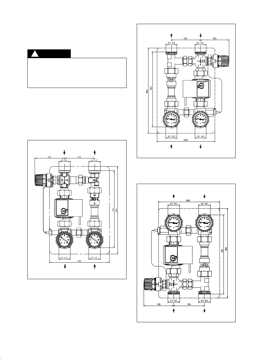
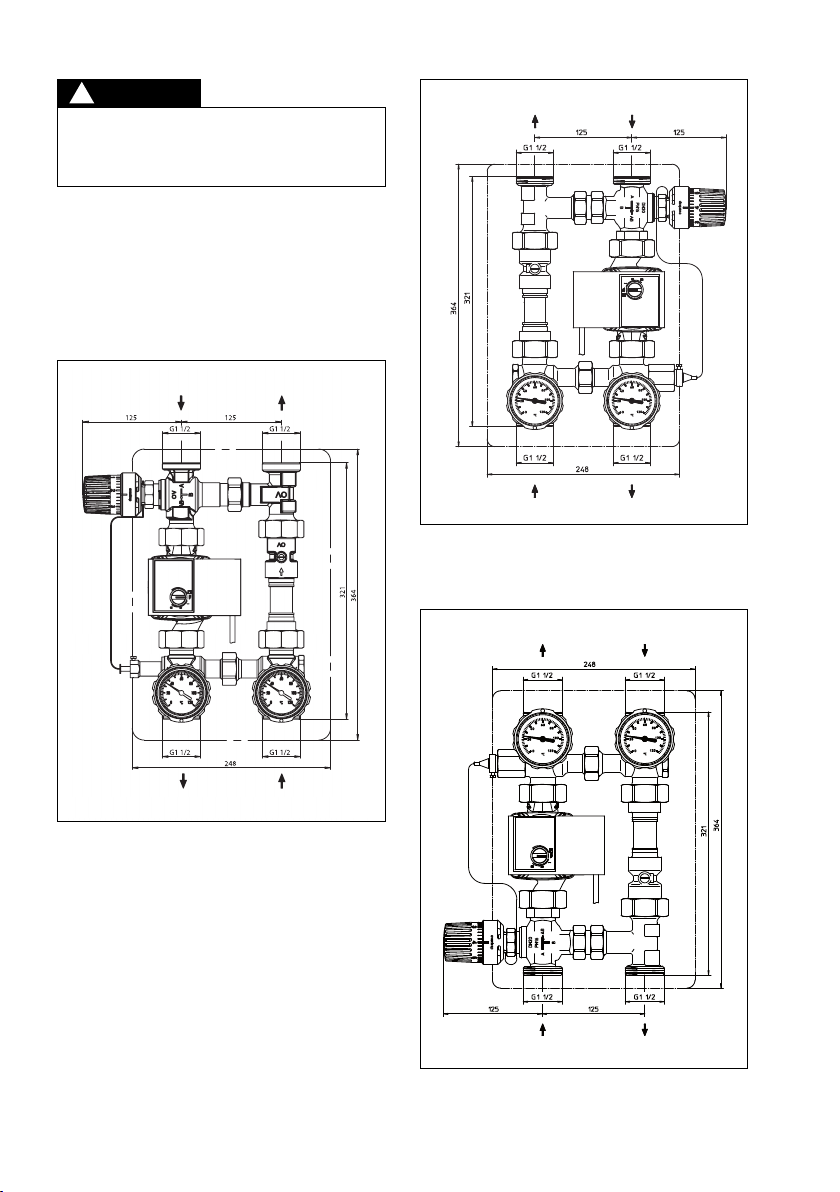
Bauhöhe Isolierung:
„Regumat-130“ DN 25
mit Standardisolierung 364 mm
„Regumat-180“ DN 25
mit Universalisolierung 414 mm
„Regumat-180“ DN 25
mit Standardisolierung 513 mm
„Regumat-180“ DN 32
mit Standardisolierung 472 mm
Breite Isolierung 248 mm
Achsabstand 125 mm
Anschlüsse DN 25 G 1½ flachdichtend
Anschlüsse DN 32 G 2 flachdichtend
2.2 Gefahren, die vom Einsatzort und Transport
ausgehen können
Der Fall eines externen Brandes wurde bei der Ausle-
gung des Heizkessel-Anbindesystems nicht berück-
sichtigt.
Jede darüber hinausgehende und/oder andersartige
Verwendung des Heizkessel-Anbindesystems ist un-
tersagt und gilt als nicht bestimmungsgemäß. Ansprü-
che jeglicher Art gegen den Hersteller und/oder seine
Bevollmächtigten wegen Schäden aus nicht bestim-
mungsgemäßer Verwendung können nicht anerkannt
werden.
Zur bestimmungsgemäßen Verwendung zählt auch die
korrekte Einhaltung der Einbau- und Betriebsanlei-
tung.
ACHTUNG
WARNUNG
!

3
Es ist durch geeignete Maßnahmen (z. B. Sicher-
heitsventile) sicherzustellen, dass die max. Be-
triebsdrücke sowie die max. und min. Betriebs-
temperaturen nicht überschritten bzw.
unterschritten werden.
4.3 Materialien
Armaturen: Messing
Pumpe: Gehäuse aus Grauguss
Isolierung: EPP
Dichtungen: EPDM
Flanschrohr: upfer
Temperaturregler: Gehäuse aus PA
4.4 Abmessungen/Anschlussmaße
Abb. 4.2 „Regumat RTA-130 VL“ DN25
mit Standardisolierung
Vorlauf auf der linken Seite
essel ist unterhalb der Station angeordnet
Abb. 4.3 „Regumat RTA-130 TOP“ DN25
mit Standardisolierung
Vorlauf auf der rechten Seite
essel ist oberhalb der Station angeordnet
Abb. 4.1 „Regumat RTA-130 VR“ DN25 mit
Standardisolierung
Vorlauf auf der rechten Seite
essel ist unterhalb der Station angeordnet
Rücklauf vom
HK/Puffers eicher
Vorlauf zum
HK/Puffers eicher
Rücklauf zum Kessel
min. Tem eratur 55°C
Vorlauf
vom Kessel
Vorlauf
vom Kessel
Rücklauf zum Kessel
min. Tem eratur 55°C
Rücklauf zum Kessel
min. Tem eratur 55°C
Vorlauf
vom Kessel
Rücklauf vom
HK/Puffers eicher
Vorlauf zum
HK/Puffers eicher
Medium: Nicht aggressive Flüssigkeiten (z. B. Wasser
und geeignete Wasser-Glykolgemische gemäß VDI
2035). Nicht für Dampf, ölhaltige und aggressive Me-
dien geeignet.
GEFAHR
!
Vorlauf zum
HK/Puffers eicher
Rücklauf vom
HK/Puffers eicher

4
Abb. 4.4 „Regumat RTA-180“ DN25
mit Universalisolierung
Vorlauf auf der rechten Seite
essel ist unterhalb der Station angeordnet
Rücklauf vom
HK/Puffers eicher
Vorlauf zum
HK/Puffers eicher
Rücklauf zum Kessel
min. Tem eratur 55°C
Vorlauf
vom Kessel
Abb. 4.5 „Regumat RTA-180“ DN25
mit Standardisolierung
Vorlauf auf der rechten Seite
essel ist unterhalb der Station angeordnet
Rücklauf vom
HK/Puffers eicher
Vorlauf zum
HK/Puffers eicher
Rücklauf zum Kessel
min. Tem eratur 55°C
Vorlauf
vom Kessel
Abb. 4.6 „Regumat RTA-180“ DN32
mit Standardisolierung
Vorlauf auf der rechten Seite
essel ist unterhalb der Station angeordnet
Rücklauf vom
HK/Puffers eicher
Vorlauf zum
HK/Puffers eicher
Rücklauf zum Kessel
min. Tem eratur 55°C
Vorlauf
vom Kessel

5
4.5 Durchflussdiagramm
Durchflussdiagramm „Regumat RTA-130/180“ DN 25
Druckverlust ⌬p [mbar]
Druckverlust ⌬p [Pascal]
·
Durchfluss V [l/h]
Druckverlust ⌬p [mbar]
Druckverlust ⌬p [Pascal]
·
Durchfluss V [l/h]
Durchflussdiagramm „Regumat RTA-180“ DN 32

6
6 Einbau
Montage, Erstinbetriebnahme, Wartung und Repara-
turen müssen von autorisierten Fachkräften (Heizungs-
fachbetrieb / Vertragsinstallationsunternehmen) durch-
geführt werden. (EN 5011 Teil 1 und VDE 1000 Teil 10
für Arbeiten an elektrischen Einrichtungen.)
Warnhinweise unter Abschnitt 2 (Sicherheitshin-
weise) beachten!
Bevor das Heizkessel-Anbindesystem in die Rohrlei-
tung eingesetzt wird, ist diese gründlich zu spülen.
Die Einbaulage ist beliebig (waagerecht, schräg oder
senkrecht, in steigende oder fallende Abschnitte). Es
ist jedoch darauf zu achten, dass die Armatur immer
in Pfeilrichtung durchströmt wird.
Die Armaturengruppe wird vormontiert geliefert. Bei
Betrieb der Heizungsanlage muss der Schlitz der Auf-
stellung der Schwerkraft in waggerechter Stellung sein.
Abb. 6 Stellung Schwerkraftsperre
Vor Arbeiten an der Anlage sicherstellen, dass die
Rohrleitungen und die Armaturen abgekühlt und
entleert sind!
Elektrische omponenten (Regler, Pumpen, etc.)
vor Beginn der Arbeiten vom Strom trennen.
Nach der Montage sind alle Montagestellen auf Dicht-
heit zu überprüfen.
5 Aufbau und Funktion
5.1 Übersicht und Funktionsbeschreibung
Das Heizkessel-Anbindesystem RTA ist wahlweise mit
Temperaturregler 40-70 °C oder 50-80 °C (nur „Regu-
mat RTA-180“) lieferbar.
Empfohlener Einstellbereich Temperaturregler 40-70
°C: Stellung 4-5
Empfohlener Einstellbereich Temperaturregler 50-80
°C: Stellung 2-3
Die Empfehlungen der Heizkesselhersteller sind zu be-
achten!
Mit dem oben genannten empfohlenen Einstellbereich
des jeweiligen Temperaturreglers wird eine Rücklauf-
temperatur von ca. 55°C erreicht.
Das Heizkessel-Anbindesystem ermöglicht den An-
schluss des Heizsystems/Speichers an den Feststoff-
kessel. Ein im Rücklauf integriertes Dreiwege-Misch-
ventil sorgt für das schelle Erreichen unkritischer
esselrücklauf-Temperaturen.
Im Anfahrbetrieb läuft der esselkreis zunächst im
urzschluss. Über den Bypass wird dem Rücklauf di-
rekt heißes Vorlaufwasser zugeführt. Nach Erreichen
der eingestellten Rücklauftemperatur (in der Regel
55°C) beginnt das Mischventil den Heiz- bzw. Puffer-
kreis zu öffnen und verhindert im weiteren Betrieb das
Absinken der Rücklauftemperatur unter den am Tem-
peraturregler eingestellten Wert.
Einbaubeispiel:
Abb. 5 Einbindung eines „Regumaten“ zwischen Fest-
stoffkessel und Pufferspeicher
Das Schnittbild (Abb.5) ist nur eine schematische
Darstellung und gibt einen unverbindlichen Hinweis
auf eine mögliche hydraulische Schaltung. Die Si-
cherheitseinrichtungen sind nach den gültigen Nor-
men, den anerkannten Regeln der Technik und
den örtlichen Vorschriften auszuführen.
5.2 Kennzeichnungen
– Angabe der CE-Kennzeichnung auf der Pumpe:
CE marking
– Angaben auf dem Gehäu e:
V Oventrop
DN Nennweite
ACHTUNG
WARNUNG
!
!

7
6.1 Montage des Temperaturreglers
– Zur Montage des Temperaturreglers die Schraub-
kappe am Mischventil entfernen.
– Den Temperaturregler am Mischventil anschrauben
(Überwurfmutter fest anziehen, jedoch keine Gewalt
anwenden!)
– Fühler in die Tauchhülse einschieben und mit der
Schraube sichern.
– Das aufgewickelte apillarrohr innerhalb der Isolie-
rung verlegen.
6.2 Einregulierung der Rücklaufanhebung
– Handrad einstellen (Einstellbereich siehe 5.1).
– Die Anlage in stationären Betrieb bringen (mindes-
tens eine Stunde Laufzeit).
– Dreiwege-Mischventil gegebenenfalls am Tempe-
raturregler so nachregulieren, dass sich eine Rück-
lauftemperatur von 55°C einstellt. Von Ziffer zu Ziffer
beträgt die Temperaturänderung 5 (Verstellbereich
30 , ennzeichnung des Handrades: 1-7).
7 Betrieb
7.1 Entlüftung der Anlage
Vor der Inbetriebnahme muss die Anlage aufgefüllt
und entlüftet werden. Dabei sind die zulässigen Be-
triebsdrücke zu berücksichtigen.
7.2 Korrekturfaktoren für Wasser-Glykol-Gemische
Die orrekturfaktoren der Frostschutzmittelhersteller
müssen bei der Durchflusseinstellung berücksichtigt
werden.
8 Zubehör
Die Tüllenanschluss-Sets zum Anbinden an das Rohr-
leitungssystem sind separat zu bestellen.
Das gesamte Zubehörsortiment finden Sie im ata-
log.
9 Wartung und Pflege
Die Armatur ist wartungsfrei.
10 Gewährleistung
Es gelten die zum Zeitpunkt der Lieferung gültigen
Gewährleistungsbedingungen von Oventrop.

8
Valves, controls and systems
Boiler connection system “Regumat RTA-130“ DN25
“Regumat RTA-180“ DN25 / DN32
for solid fuel boilers
Installation and operating instructions for specialists
EN
Read installation and operating instructions in their
entirety before installing the connection system!
Installation, initial operation, operation and main-
tenance must only be carried out by qualified tra-
desmen!
The installation and operating instructions, as well
as other valid documents must remain with the
user of the system!
Illustr. 1.1 „Regumat RTA-180“ DN 25 with universal
insulation
1.2 Keeping of documents
The installation and operating instructions should be
kept by the user of the system.
1.3 Copyright
The installation and operating instructions are copy-
righted.
1.4 Symbol explanation
Safety guidelines are displayed by symbols. These
guidelines are to be observed to avoid accidents, da-
mage to property and malfunctions.
1 General information
1.1 Information regarding installation and
operating instructions
These installation and operating instructions serve the
trained tradesman to install the boiler connection sys-
tem professionally and to put it into operation.
Other valid documents – manuals of all system com-
ponents (especially the operating instructions of the
circulation pump) as well as valid technical rules –
must be observed.
Content
1 General information . . . . . . . . . . . . . . . . . . . . . 9
2 Safety notes . . . . . . . . . . . . . . . . . . . . . . . . . . 10
3 Transport, storage and packaging . . . . . . . . . 10
4 Technical data . . . . . . . . . . . . . . . . . . . . . . . . . 10
5 Construction and function . . . . . . . . . . . . . . . . 14
6 Installation . . . . . . . . . . . . . . . . . . . . . . . . . . . . 14
7 Operation . . . . . . . . . . . . . . . . . . . . . . . . . . . . . 15
8 Accessories . . . . . . . . . . . . . . . . . . . . . . . . . . . 15
9 Maintenance . . . . . . . . . . . . . . . . . . . . . . . . . . 15
10 Warranty . . . . . . . . . . . . . . . . . . . . . . . . . . . . . 15
Subject to technical modification without notice.
For an overview of our global presence visit
www.oventrop.com.
DANGER indicates an immi-
nent dangerous situation which will lead to death or
serious injury if the safety guidelines are not obser-
ved.
WARNING indicates a pos-
sible dangerous situation which may lead to death or
serious injury if the safety guidelines are not obser-
ved.
ATTENTION indicates a pos-
sible damage to property which may occur if the safety
guidelines are not observed.
PRECAUTION indicates a
possible dangerous situation which may lead to minor
or moderate injury if the safety guidelines are not ob-
served.
!
DANGER
!
ATTENTION
WARNING
!
PRECAUTI N
!

9
In solid fuel boilers, return temperatures below
50°C lead to the formation of condensation and
pitch!
Heavy product assembly!
Risk of injury! Suitable means of transport and
hoisting devices have to be used. Wear protective
clothing (e.g. safety shoes) during installation and
use protective devices. External components such
as handwheels, levers etc. must not be misused
for the absorption of external forces, e.g. as con-
nection point for lever tools etc.
Hot and cold surfaces!
Risk of injury! Only touch with safety gloves and
inactivate installation before work commences.
Sharp edges!
Risk of injury! Only touch with safety gloves. Thre-
ads, edges and bore holes are sharp.
Allergies!
Health hazard! Do not touch the boiler connection
system and avoid any contact if allergies against
the used materials are known.
2 Safety notes
2.1 Correct use
Safety in operation is only guaranteed if the boiler con-
nection system is used correctly.
The boiler connection system allows the connection
of the heating system / storage cylinder to the solid
fuel boiler. A three-way mixing valve integrated in the
return ensures that uncritical boiler return temperatures
are reached quickly.
3 Transport, storage and
packaging
3.1 Extent of supply
– Pre-assembled “„Regumat RTA“ DN25 / DN32 pro-
duct group
–Temperature controller
– Insulation
– Sealing set (4-fold)
–Pump cable (for stations with high-efficiency pump)
3.2 Transport inspection
Upon receipt check delivery for any damages caused
during transit.
Any damage must be reported immediately upon re-
ceipt.
3.3 Packaging
Packaging material is to be disposed of environmen-
tally friendly.
4 Technical data
4.1 Models
Oventrop offers the following models:
-
“Regumat RTA-130 VR“ DN25 with standard insulation
–
“Regumat RTA-130 VL“ DN25 with standard insulation
-
“Regumat RTA-130 TOP“ DN25 with standard insulation
- “Regumat RTA-180“ DN25 with universal insulation
- “Regumat RTA-180“ DN25 with standard insulation
- “Regumat RTA-180“ DN32 with standard insulation
4.2 Performance data
Dimension DN25 / DN32
Max. operating pressure 10 bar
Max. operating temperature for
“Regumat” with standard pump 110 °C
Max. operating temperature for
“Regumat” with universal thermal
insulation and high-efficiency pump 95 °C
Max. operating temperature for
“Regumat” with standard thermal
insulation and high-efficiency pump 85 °C
kvs value 3.9 / 5.3 (DN32)
Recommended
return temperature 55 °C
Opening pressure check valve 20 mbar
Height insulation:
“Regumat-130“ DN25
with standard insulation 364mm
“Regumat-180“ DN 25
with universal insulation 414 mm
“Regumat-180“ DN 25
with standard insulation 513 mm
“Regumat-180“ DN 32
with standard insulation 472 mm
Width insulation 248 mm
Distance between pipe centres 125 mm
Connections DN 25 G 11⁄2flat sealing
Connections DN 32 G 2 flat sealing
Fluids: Non-aggressive fluids (e.g. water and suitable
water and glycol mixtures according to VDI 2035). Not
suitable for steam or oily and aggressive fluids.
2.2 Possible dangers at the installation location
and during transport
The case of an external fire has not been taken into
consideration when constructing the boiler connection
system.
Any use of the boiler connection system outside of
the above applications will be considered as non-com-
pliant and misuse. Claims of any kind against the ma-
nufacturer and/or his authorised representatives due
to damages caused by incorrect use cannot be ac-
cepted.
The observance of the installation and operating in-
structions is part of the compliance terms.
ATTENTION
WARNING
!

10
Suitable measures (e.g. safety valves) have to be
taken to ensure that the maximum working pres-
sures and maximum and minimum working tem-
peratures are not exceeded or undercut.
4.3 Materials
Valves: brass
Pump: cast iron body
Insulation: EPP
Seals: EPDM
Flanged pipe: copper
Temperature controller: body made of PA
4.4 Dimensions/Connection dimensions
Ilustr. 4.2 “Regumat RTA-130 VL“ DN25
with standard insulation
Supply on left hand side
Boiler is located below the “Regumat”
Illustr. 4.3“Regumat RTA-130 TOP“ DN25
with standard insulation
Supply on right hand side
Boiler is located above the “Regumat”
Illustr. 4.1 “Regumat RTA-130 VR“ DN25
with standard insulation
Supply on right hand side
Boiler is located below the “Regumat”
Su ly from
boiler
Return to boiler
Min. tem erature 55°C
Return to boiler
Min. tem erature 55°C
Su ly from
boiler
Return from radiator/
buffer storage cylinder
Su ly to radiator/
buffer storage cylinder
DANGER
!
Return from radiator/
buffer storage cylinder
Su ly to radiator/
buffer storage cylinder
Return to boiler
Min. tem erature 55°C
Su ly from
boiler
Su ly to radiator/
buffer storage cylinder
Return from radiator/
buffer storage cylinder

11
Illustr. 4.5 “Regumat RTA-180“ DN 25 with
standard insulation
Supply on right hand side
Boiler located below the “Regumat”
Illustr. 4.6 “Regumat RTA-180“ DN32 with
standard insulation
Supply on right hand side
Boiler is located below the “Regumat”
Illustr. 4.4 “Regumat RTA-180“ DN25 with
universal insulation
Supply on right hand side
Boiler is located below the “Regumat”
Return from radiator/
buffer storage cylinder
Su ly to radiator/
buffer storage cylinder
Return to boiler
Min. tem erature 55°C
Su ly from
boiler
Return from radiator/
buffer storage cylinder
Su ly to radiator/
buffer storage cylinder
Return to boiler
Min. tem erature 55°C
Su ly from
boiler
Return from radiator/
buffer storage cylinder
Su ly to radiator/
buffer storage cylinder
Return to boiler
Min. tem erature 55°C
Su ly from
boiler

12
4.5 Flow charts
Flow chart “Regumat RTA-130/180“ DN 25
Pressure loss ⌬p [mbar]
Pressure loss ⌬p [Pascal]
·
Flow rate V [l/s]
Pressure loss ⌬p [mbar]
Pressure loss ⌬p [Pascal]
·
Flow rate V [l/s]
Flow chart “Regumat RTA-180“ DN 25

13
5 Construction and function
5.1 Summary and functional description
The boiler connection system RTA is available with
temperature controller 40-70°C or 50-80°C (only “Re-
gumat RTA-180”).
Recommended control range temperature controller
40-70°C: Position 4-5
Recommended control range temperature controller
50-80°C: Position 2-3
The recommendations of the boiler manufacturers
must be observed!
A return temperature of about 55°C is achieved with
the a.m. control range of the corresponding tempera-
ture controller.
The boiler connection system allows the connection
of the heating system/storage cylinder to the solid fuel
boiler. A three-way mixing valve integrated in the return
ensures that uncritical boiler temperatures are reached
quickly.
During start-up, the boiler is short circuited. Hot flow
water is directed to the boiler return via the bypass.
Having reached the set return temperature (normally
55°C), the mixing valve opens the heating or buffer
storage cylinder circuit and prevents the return tem-
perature from dropping below the value set at the tem-
perature controller.
Example of installation:
6 Installation
Installation, initial operation, maintenance and repairs
have to be carried out by authorised and qualified tra-
desmen (EN 5011 part 1 and VDE 1000 part 10 for
work on electrical installations).
Warning advice under paragraph 2 (safety notes)
must be observed!
The pipework has to be flushed thoroughly before in-
stalling the boiler connection system. It can be installed
in any position (horizontal, inclined or vertical, in as-
cending or descending sections) provided that the di-
rection of flow conforms to the arrow on the valve.
The product group is supplied pre-assembled.
During operation, the slot for opening the check valve
must be in horizontal position.
Illustr. 5 Installation of a “Regumat“ between a solid
fuel boiler and a buffer storage cylinder
Illustr. 6 Position of the check valve
The example of installation (Illustr. 5) is only a sche-
matic illustration and shows a possible hydronic
circuitry. The safety components must be carried
out in accordance with the valid standards, ap-
proved rules of technology and local regulations.
Before starting work, make sure that the pipework
and the components have cooled down and been
drained!
Before starting work, disconnect electrical com-
ponents (controllers, pumps etc.) from power.
5.2 Markings
– CE marking on the pump:
CE marking
– Information on the body:
V Oventrop
DN Size
After installation, check all installation points for
leaks.
ATTENTION
WARNING
!
!

14
6.1 Installation of the temperature controller
– To mount the temperature controller, remove the
screwed cap of the mixing valve.
– Screw the temperature controller onto the mixing
valve (tighten collar nut firmly, but do not use ex-
cessive force!).
– Insert sensor into the immersion pocket and secure
with the screw.
– Place coil of capillary inside the insulation.
6.2 Setting of the return temperature increase
–Set handwheel (control range see 5.1).
– Operate the installation in a stationary position for
at least one hour.
– If required, re-adjust three-way mixing valve at the
temperature controller so that a return temperature
of 55°C is reached. The temperature modification
between the figures amounts to 5 (setting range
30 , graduation on handwheel: 1-7).
7 peration
7.1 Deaeration of the system
Before initial operation, the installation must be filled
and bled with due consideration of the permissible
operating pressures.
7.2 Correction factors for water and glycol mixtu-
res
The correction factors of the antifreeze liquid manu-
facturers must be observed when setting the flow rate.
8 Accessories
The tailpipe sets for the connection to the pipework
are to be ordered separately.
The complete range of accessories can be found in
the catalogue.
9 Maintenance
The station is maintenance-free.
10 Warranty
Oventrops warranty conditions valid at the time of
supply are applicable.

1515
Robinetterie «haut de gamme» + Systèmes
Système de raccordement pour chaudières «Regumat RTA-130» DN25
«Regumat RTA-180» DN25 / DN32
pour chaudières à combustibles solides
Notice d’installation et d’utilisation pour le professionel
FR
Lire intégralement la notice d’installation et d’utili-
sation avant le montage du système de raccorde-
ment pour chaudières!
Le montage, la mise en route, le service et l’entre-
tien ne doivent être effectués que par des profes-
sionnels qualifiés!
Remettre la notice d’installation et d’utilisation ainsi
que tous les documents de référence à l’utilisateur
de l’installation!
Fig. 1.1 «Regumat RTA-180» DN25 avec isolation
universelle
1.2 Conservation des documents
Cette notice d’installation et d’utilisation doit être con-
servée par l’utilisateur de l’installation pour consultation
ultérieure.
1.3 Protection de la propriété intellectuelle
La présente notice d’installation et d’utilisation est
protégée par le droit de la propriété intellectuelle.
1.4 Signification des symboles
Les consignes de sécurité sont identifiées par des
symboles. Ces consignes doivent être respectées pour
éviter des accidents, des dégâts matériels et des dys-
fonctionnements.
1 Généralités
1.1 Informations sur la notice d’installation et d’uti-
lisation
Cette notice d’installation et d’utilisation a pour but
d’aider le professionnel à installer et mettre en service
le système de raccordement pour chaudières dans
les règles de l’art.
Autres documents de référence – Les notices de tous
les composants du système, surtout la notice d’in-
stallation du circulateur, ainsi que les règles techniques
en vigueur - sont à respecter.
Contenu
1 Généralités . . . . . . . . . . . . . . . . . . . . . . . . . . . 17
2 Consignes de sécurité . . . . . . . . . . . . . . . . . . 18
3 Transport, stockage et emballage . . . . . . . . . 18
4 Données techniques . . . . . . . . . . . . . . . . . . . 18
5 Construction fonctionnement . . . . . . . . . . . . . 22
6 Montage . . . . . . . . . . . . . . . . . . . . . . . . . . . . . 22
7 Opération . . . . . . . . . . . . . . . . . . . . . . . . . . . . 23
8 Accessoires . . . . . . . . . . . . . . . . . . . . . . . . . . 23
9 Entretien . . . . . . . . . . . . . . . . . . . . . . . . . . . . . 23
10 Garantie . . . . . . . . . . . . . . . . . . . . . . . . . . . . . 23
Sous réserve de modifications techniques.
Vous trouverez une vue d’ensemble des interlocu-
teurs dans le monde entier sur www.oventrop.com.
DANGER signifie une situa-
tion immédiate dangereuse qui mènera à la mort et
provoquera des blessures graves en cas de non-ob-
servation des consignes de sécurité.
AVERTISSEMENT signifie
une situation potentiellement dangereuse qui peut me-
ner à la mort ou provoquer des blessures graves en
cas de non-observation des consignes de sécurité.
ATTENTION signifie que des
dégâts matériels peuvent être causés en cas de non-
observation des consignes de sécurité.
PRECAUTION signifie une si-
tuation potentiellement dangereuse qui peut entraîner
des blessures minimes ou légères en cas de non-ob-
servation des consignes de sécurité.
!
DANGER
!
ATTENTION
AVERTISSEMENT
!
PRECAUTI N
!

16
Dans les chaudières à combustibles solides, des
températures du retour inférieures à 50°C mènent
à la formation d’eau de condensation ou de bi-
stre!
Groupe de robinetterie lourd
Risque de blessure! Utiliser des moyens de trans-
port et de levage appropriés. Porter des vêtements
de protection (par ex. chaussures de sécurité) et
utiliser des dispositifs de protection pendant le
montage. Les accessoires de robinetterie tels que
poignées manuelles ou manettes ne doivent pas
être utilisés comme point d’attache pour des engins
de levage etc.
Surfaces chaudes ou froides!
Risque de blessure! Ne pas toucher sans gants
de protection et mettre le système hors service
avant le début des travaux.
Arêtes vives!
Risque de blessure! Les filetages, perçages et
carnes présentent des arêtes vives.
Allergies!
Risque de santé! Ne pas toucher le système de
raccordement pour chaudières en cas d’allergies
aux matériaux utilisés.
2 Consignes de sécurité
2.1 Utilisation conforme
La sûreté de fonctionnement du système de raccor-
dement pour chaudières n’est garantie que s’il est af-
fecté à l’utilisation prévue.
Le système de raccordement pour chaudières permet
le raccordement du système de chauffage/ballon d’eau
chaude à la chaudière à combustibles solides. Une
vanne mélangeuse à trois voies intégrée sur le retour
sert à l’obtention rapide de températures non critiques
pour la chaudière.
3 Transport, stockage et
emballage
3.1 Fourniture
– Groupe de robinetterie «Regumat RTA-180» DN25/
DN32 prémonté
–Régulateur de température
– Isolation
– Jeu d’étanchéité (par 4)
–Câble de circulateur (pour stations avec circulateurs
à haut rendement)
3.2 Inspection après transport
Examiner la livraison immédiatement après réception
pour vérifier l’absence de dommages dus au transport.
Si des dommages ou d’autres défauts sont constatés,
n’accepter la marchandise que sous réserve. Emettre
une réclamation en respectant les délais applicables.
3.3 Emballage
Le matériel d’emballage est à éliminer dans le respect
de l’environnement.
4 Données techniques
4.1 Modèles
Oventrop propose les modèles suivants:
– «Regumat RTA-130 VR» DN25
avec isolation standard
– «Regumat RTA-130 VL» DN25
avec isolation standard
– «Regumat RTA-130 TOP» DN25
avec isolation standard
– «Regumat RTA-180» DN25
avec isolation universelle
– «Regumat RTA-180» DN25
avec isolation standard
– «Regumat RTA-180» DN32
avec isolation standard
4.2 Données techniques
Dimension DN 25 / DN 32
Pression de service max. 10 bar
Température de service max. pour
«Regumat» avec circulateur standard
110°C
Température de service max. pour
«Regumat» avec isolation universelle
et circulateur à haut rendement 95°C
Température de service max. pour
«Regumat» avec isolation standard
et circulateur à haut rendement 85°C
Valeur kvs 3,9 / 5,3 (DN 32)
Température de retour
recommandée 55°C
Pression d’ouverture clapet ATS 20 mbars
Hauteur isolation:
«Regumat-130» DN 25
avec isolation standard 364mm
«Regumat-180» DN 25
avec isolation universelle 414 mm
«Regumat-180» DN 25
avec isolation standard 513 mm
«Regumat-180» DN 32
avec isolation standard 472 mm
2.2 Risques liés au lieu d’installation et au trans-
port
Le cas d’un incendie n’a pas été pris en considération
lors de la conception du système de raccordement
pour chaudières.
Toute utilisation différente du système de raccorde-
ment pour chaudières est interdite et réputée non con-
forme.
Les revendications de toute nature à l’égard du fabri-
cant et/ou ses mandataires pour des dommages ré-
sultant d’une utilisation non conforme ne seront pas
acceptées.
L’utilisation conforme comprend aussi l’utilisation cor-
recte de la notice d’installation et d’utilisation.
ATTENTION
AVERTISSEMENT
!

17
Il convient d’assurer par des mesures appropriées
(par ex. soupapes de sécurité) que les pressions
de service max. ainsi que les températures de ser-
vice max. et min. ne soient pas dépassées ni vers
le haut ni vers le bas.
4.3 Matériaux
Robinetterie: laiton
Circulateur: corps en fonte grise
Isolation: EPP
Joints: EPDM
Tuyau à brides: cuivre
Régulateur de
température: corps en PA
4.4 Encombrements/Cotes de raccordement
Fig. 4.2 «Regumat RTA-130 VL» DN25
avec isolation standard
Aller à gauche
Chaudière montée en dessous de la station
Fig. 4.3 «Regumat RTA-130 TOP» DN25
avec isolation standard
Aller à droite
Chaudière montée au-dessus de la station
Fig. 4.1 «Regumat RTA-130 VR» DN25
avec isolation standard
Aller à droite
Chaudière montée en dessous de la station
Retour venant du radiateur/
ballon tam on
Aller vers le radiateur/
ballon tam on
Retour vers la chaudière
Tem érature min. 55°C
Aller venant de
la chaudière
Aller venant de
la chadière
Retoure vers la chaudière
Tem érature min. 55°C
Retoure vers la chadière
Tem érature min. 55°C
Aller venant de
la chaudière
Retoure venant du radiateur/
ballon tam on
Aller vers le radiateur/
ballon tam on
DANGER
!
Fluide: Fluides non-agressifs (par ex. eau et mélanges
eau-glycol adéquats selon VDI 2035). Ne convient pas
à la vapeur et aux fluides huileux et agressifs.
Aller vers le radiateur/
ballon tam on
Retoure venant du
radiateur/ballon tam on
Largeur isolation 248 mm
Entraxe 125 mm
Raccordements DN 25 G 1½ à joint plat
Raccordements DN 32 G 2 à joint plat

18
Fig. 4.5 «Regumat RTA-180» DN25
avec isolation standard
Aller à droite
Chaudière montée en dessous de la station
Fig. 4.6 «Regumat RTA-180» DN32
avec isolation standard
Aller à droite
Chaudière montée en dessous de la station
Fig. 4.4 «Regumat RTA-180» DN25
avec isolation universelle
Aller à droite
Chaudière montée en dessous de la station
Retoure venant du
radiateur/ballon tam on
Aller vers le
radiateur/ballon tam on
Retoure vers la chaudière
Tem érature min. 55°C
Aller venant de
la chaudière
Retoure venant du
radiateur/ballon tam on
Aller vers le
radiateur/ballon tam on
Retoure vers la chaudière
Tem érature min. 55°C
Aller venant de
la chaudière
Retoure venant du
radiateur/ballon tam on
Aller vers le
radiateur/ballon tam on
Retoure vers la chaudière
Tem érature min. 55°C
Aller venant de
la chaudière

19
4.5 Diagrammes de débit
Diagramme de débit «Regumat RTA-130/180» DN 25
Perte de charge ⌬p [mbar]
Perte de charge ⌬p [Pascal]
·
Debit V [l/h]
Perte de charge ⌬p [mbar]
Perte de charge ⌬p [Pascal]
·
Debit V [l/h]
Diagramme de débit «Regumat RTA-180» DN 32

20
5 Construction et
fonctionnement
5.1 Vue d’ensemble et description du fonctionne-
ment
Le système de raccordement pour chaudières RTA
peut être sélectionné avec régulateur de température
40-70°C ou 50-80°C (seulement «Regumat RTA-180»).
Plage de réglage recommandée du régulateur de tem-
pérature 40-70°C: Position 4-5
Plage de réglage recommandée du régulateur de tem-
pérature 50-80°C: Position 2-3
Les recommandations des fabricants de chaudière
sont à respecter!
Avec la plage de réglage recommandée ci-dessus du
régulateur de température correspondant, une tem-
pérature de retour d’environ 55°C est atteinte.
Le système de raccordement pour chaudières permet
le raccordement du système de chauffage/ballon d’eau
chaude à la chaudière à combustibles solides. Une
vanne mélangeuse à trois voies intégrée sur le retour
sert à l’obtention rapide de températures non critiques
pour la chaudière.
En phase de démarrage, la chaudière fonctionne en
circuit fermé. De l’eau chaude de l’aller est ajoutée au
retour au travers du bypass. Après avoir atteint la tem-
pérature de retour réglée (en règle générale 55°C), la
vanne mélangeuse ouvre le circuit de chauffage ou le
circuit tampon et empêche une chute de la tempéra-
ture de retour en dessous de la valeur réglée au régu-
lateur de température.
Exemple d’installation:
6 Montage
Le montage, la mise en service initiale, l’entretien et
les réparations doivent être effectués par des profes-
sionnels qualifiés (professionnel du chauffage / entre-
prise d’installation agréée) (EN 5011 partie1 et VDE
1000 partie 10 pour travaux aux installations électri-
ques).
Les signalements de danger sous paragraphe
2 (consignes de sécurité) doivent être observés!
Avant le montage du système de raccordement pour
chaudières dans la tuyauterie, celle-ci doit être rincée
à fond. Le«Regumat» se monte dans n’importe quelle
position (horizontale, oblique ou verticale, dans secti-
ons en montée ou en descente) en veillant à ce que le
sens de circulation corresponde à celui de la flèche.
Le groupe de robinetterie est livré prémonté.
En pleine période de service de chauffage, la fente
servant à l’ouverture du clapet doit se trouver en po-
sition horizontale.
Fig. 5 Montage du «Regumat» entre la chaudière à
combustibles solides et le ballon tampon
Fig. 6 Position clapet ATS
L’exemple d’installation (fig.5) est seulement une
illustration schématique et donne un renvoi indi-
catif à un montage hydraulique possible. Les dis-
positifs de sécurité doivent être réalisés selon les
règles de l’art et directives locales.
Avant le début des travaux, il faut s’assurer que la
tuyauterie et la robinetterie sont refroidies et vi-
dangées!
Couper l’alimentation électrique des composants
(régulateurs, circulateurs etc.) avant le début des
travaux.
5.4 Marquages
– Marquage CE ur le circulateur:
Marquage CE
– Indication ur le corp :
V Oventrop
DN Dimen ion
Après le montage, contrôler l’étanchéité de tous les
points de montage.
ATTENTION
AVERTISSEMENT
!
!
This manual suits for next models
4
Table of contents
Languages:
Other oventrop Boiler Supplies manuals
Popular Boiler Supplies manuals by other brands

Detandt-Simon
Detandt-Simon 200 Instructions for use and maintenance

Bryan Boilers
Bryan Boilers B-26S-D brochure

AFRISO
AFRISO KSG Magnum operating instructions

Immergas
Immergas Victrix TT Series Instruction and warning book

Riello
Riello Tau Unit Oil V70 240 instruction manual

Miura
Miura CONNECT installation manual