oventrop Regumat S-130 User manual

Premium Armaturen + Systeme
Heizkessel-Anbindesystem „Regumat“ DN 25
Einbau- und Betriebsanleitung für Fachpersonal
DE
Vor dem Einbau des Heizkessel-Anbindesystems
die Einbau- und Betriebsanleitung vollständig
lesen!
Einbau, Inbetriebnahme, Bedienung und Wartung
darf nur durch geschultes Fachpersonal durchge-
führt werden!
Die Einbau- und Betriebsanleitung sowie alle mit-
geltenden Unterlagen sind an den Anlagenbetreiber
weiterzugeben!
Inhalt
1 Allgemeine Hinweise . . . . . . . . . . . . . . . . . . . 1
2 Sicherheitshinweise . . . . . . . . . . . . . . . . . . . . 2
3 Transport, Lagerung und Verpackung . . . . . . 2
4 Technische Daten . . . . . . . . . . . . . . . . . . . . . 2
5 Aufbau und Funktion . . . . . . . . . . . . . . . . . . . 5
6 Einbau . . . . . . . . . . . . . . . . . . . . . . . . . . . . . . 7
7 Betrieb . . . . . . . . . . . . . . . . . . . . . . . . . . . . . . 8
8 Zubehör . . . . . . . . . . . . . . . . . . . . . . . . . . . . . 8
9 Wartung und Pflege . . . . . . . . . . . . . . . . . . . . 8
10 Garantie . . . . . . . . . . . . . . . . . . . . . . . . . . . . . 8
Abb. 1.1 „Regumat M3-180“ DN25 mit Pumpenkugel-
hahn
1 Allgemeine Hinweise
1.1 Informationen zur Betriebsanleitung
Diese Einbau- und Betriebsanleitung dient dem ge-
schulten Fachpersonal dazu, das Heizkessel-
Anbindesystem fachgerecht zu installieren und in Be-
trieb zu nehmen.
Mitgeltende Unterlagen – Anleitungen aller Anlagen-
komponenten, insbesondere die Bedienungsanleitung
der Umwälzpumpe, sowie geltende technische Regeln
– sind einzuhalten.
1.2 Aufbewahrung der Unterlagen
Diese Einbau- und Betriebsanleitung ist vom Anlagen-
betreiber zum späteren Gebrauch aufzubewahren.
1.3 Urheberschutz
Die Einbau- und Betriebsanleitung ist urheberrechtlich
geschützt.
1.4 Symbolerklärung
Hinweise zur Sicherheit sind durch Symbole gekenn-
zeichnet. Diese Hinweise sind zu befolgen, um Unfälle,
Sachschäden und Störungen zu vermeiden.
Technische Änderungen vorbehalten.
135608080 02/2017
OVENTROP GmbH & Co. KG
Paul-Oventrop-Straße 1
D-59939 Olsberg
Telefon +49 (0)2962 82-0
Telefax +49 (0)2962 82-400
E-Mail mail@oventrop.de
nternet www.oventrop.com
Eine Übersicht der weltweiten Ansprechpartner
finden Sie unter www.oventrop.de.
GEFAHR weist auf eine
unmittelbar gefähr-liche Situation hin, die zum Tod
oder zu schweren Verletzungen führen wird, wenn die
Sicherheitsmaßnahmen nicht befolgt werden.
WARNUNG weist auf eine
möglicherweise gefährliche Situation hin, die zum Tod
oder zu schweren Verletzungen führen kann, wenn die
Sicherheitsmaßnahmen nicht befolgt werden.
ACHTUNG weist auf
mögliche Sachschäden hin, welche entstehen können,
wenn die Sicherheitsmaßnahmen nicht befolgt wer-
den.
VORS CHT weist auf eine
möglicherweise gefährliche Situation hin, die zu ge-
ringfügigen oder leichten Verletzungen führen kann,
wenn die Sicherheitsmaßnahmen nicht befolgt
werden.
GEFAHR
ACHTUNG
!
WARNUNG
!
V RSICHT
!
!

2
3 Transport, Lagerung
und Verpackung
3.1 Lieferumfang
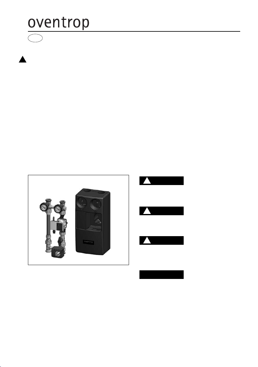
– Vormontierte „Regumat“ DN25 Armaturengruppe
– Wärmedämmung
– Bei „Regumat-130“: mit Standard Wärmedäm-
mung; bestehend aus Ober- und Unterschale
– Bei „Regumat-180“: mit universeller, modular auf-
gebauter Wärmedämmung; bestehend aus Ober-
schale, Unterschale und Einlegeblock geeignet für
den Einbau von handelsüblichen Hocheffizienz-
pumpen
– Dichtungssatz (4-fach)
– Pumpen-Einbauset (bei Stationen ohne Pumpe)
Schwere Armaturengruppe!
Verletzungsgefahr! Geeignete Transport- und
Hebemittel verwenden. Geeignete Schutzausstat-
tung (z. B. Sicherheitsschuhe) während der
Montage tragen und Schutzvorrichtungen benut-
zen. Armaturaufbauten wie Handräder oder Griffe
dürfen nicht zur Aufnahme von äußeren Kräften,
wie z. B. als Anbindungspunkte für Hebezeuge
usw. zweckentfremdet werden.
Heiße oder kalte berflächen!
Verletzungsgefahr! Nur mit geeigneten Schutz-
handschuhen anfassen. Bei Betrieb kann die
Armaturengruppe die Medientemperatur annehmen.
Scharfe Kanten!
Verletzungsgefahr! Nur mit geeigneten Schutz-
handschuhen anfassen. Gewinde, Bohrungen und
Ecken sind scharfkantig.
Allergien!
Gesundheitsgefahr! Die Armaturengruppe nicht
berühren und jeglichen Kontakt vermeiden, falls
Allergien gegenüber den verwendeten Materialien
bekannt sind.
WARNUNG
!
2 Sicherheitshinweise
2.1 Bestimmungsgemäße Verwendung
Die Betriebssicherheit ist nur bei bestimmungs-
gemäßer Verwendung des Heizkessel-Anbindesystems
gewährleistet.
Das Heizkessel-Anbindesystem ermöglicht eine
kosten- und zeitsparende Montage des Heizkessels
an die Rohrleitungs-systeme.
Jede darüber hinausgehende und/oder andersartige
Verwendung des Heizkessel-Anbindesystems ist
untersagt und gilt als nicht bestimmungsgemäß.
Ansprüche jeglicher Art gegen den Hersteller und/oder
seine Bevollmächtigten wegen Schäden aus nicht
bestimmungsgemäßer Verwendung können nicht
anerkannt werden.
Zur bestimmungsgemäßen Verwendung zählt auch die
korrekte Einhaltung der Einbau- und Betriebs-
anleitung.
2.2 Gefahren, die vom Einsatzort ausgehen
können
Der Fall eines externen Brandes wurde bei der Aus-
legung des Heizkessel-Anbindesystems nicht berück-
sichtigt.
3.2 Transportinspektion
Lieferung unmittelbar nach Erhalt sowie vor Einbau
auf mögliche Transportschäden und Vollständigkeit
untersuchen.
Falls derartige oder andere Mängel feststellbar sind,
Warensendung nur unter Vorbehalt annehmen. Rekla-
mation einleiten. Dabei Reklamationsfristen beachten.
3.3 Verpackung
Sämtliches Verpackungsmaterial ist umweltgerecht zu
entsorgen.
4 Technische Daten
4.1 Varianten
Diese Einbauanleitung gilt für folgende „Regumat“ Typen:
Für Pumpen mit Baulänge 130 mm:
– „Regumat S-130“ DN 25 mit Standard Wärmedäm-
mung
– „Regumat M3-130“ DN 25 mit Standard Wärme-
dämmung
– „Regumat M4-130“ DN 25 mit Standard Wärme-
dämmung
Für Pumpen mit Baulänge 180 mm:
– „Regumat S-180“ DN 25 mit Universeller Wärme-
dämmung
– „Regumat M3-180“ DN 25 mit Universeller Wärme-
dämmung
– „Regumat M4-180“ DN 25 mit Universeller Wärme-
dämmung
– „Regumat S-180“ DN 25 mit Pumpenkugelhahn mit
Universeller Wärmedämmung
– „Regumat M3-180“ DN 25 mit Pumpenkugelhahn
mit Universeller Wärmedämmung
– „Regumat M4-180“ DN 25 mit Pumpenkugelhahn
mit Universeller Wärmedämmung
4.2 Leistungsdaten
Nenngröße DN 25
Max. Betriebstemperatur
bei Standardpumpen +110°C
Max. Betriebstemperatur
bei Hocheffizienzpumpen mit
Standard Wärmedämmung +85°C
Max. Betriebstemperatur
bei Hocheffizienzpumpen mit
Universal Wärmedämmung +95°C
Max. Betriebsdruck ps: 10 bar
Öffnungsdruck des Sperrventils 20 mbar
Kv-Wert „Regumat S“ 7,4
„Regumat M3“ 4,3
„Regumat M4“ 4,2
Achsabstand 125 mm
Anschlüsse G1½
Medium: Nicht aggressive Flüssigkeiten (z. B. Wasser
und geeignete Wasser-Glykolgemische gemäß VD
2035). Nicht für Dampf, ölhaltige und aggressive Me-
dien geeignet.
Es ist durch geeignete Maßnahmen (z. B. Sicher-
heitsventile) sicherzustellen, dass die max.
Betriebsdrücke und die max. Betriebstemperatu-
ren nicht überschritten werden.
GEFAHR
!

3
4.3 Materialien
Armaturen Messing
Pumpe Gehäuse aus Grauguss
Handgriffe PA 6.6
solierung EPP
Flanschrohr Kupfer
Dichtungen EPDM
Vierwegemischer
(„Regumat M4“) Rotguss
4.4 Abmessungen/Anschlussmaße
Abb. 4.1 „Regumat S-130“ DN 25
Abb. 4.2 „Regumat M3-130“ DN 25
Abb. 4.3 „Regumat M4-130“ DN 25
Abb. 4.4 „Regumat S-180“ DN 25

4
Abb. 4.5 „Regumat M3-180“ DN 25
Abb. 4.6 „Regumat M4-180“ DN 25
Abb. 4.7 „Regumat S-180“ DN 25 mit Pumpenkugel-
hahn
Abb. 4.8 „Regumat M3-180“ DN 25 mit Pumpenku-
gelhahn

5
Abb. 4.9 „Regumat M4-180“ DN 25 mit Pumpenkugel-
hahn
4.5 Durchflussdiagramm
Durchflussdiagramm für „Regumat-130“ und
„Regumat-180“
Bei den Ausführungen mit Mischhahn steht dieser auf
Position voll geöffnet.
5 Aufbau und Funktion
5.1 Übersicht und Funktionsbeschreibung
Das Heizkessel-Anbindesystem ist wahlweise mit oder
ohne Pumpe erhältlich.
Bei der Variante ohne Pumpe werden die einzelnen
Komponenten lose zusammengeschraubt angeliefert.
Die Verbindungen sind nach Einbau der Pumpe nach-
zuziehen.
Der Anschlusskasten der Pumpe muss in 9 Uhr-Stellung
stehen.
Der Vorlauf ist werksseitig rechts angeordnet. Vor- und
Rücklauf können jedoch vor Ort individuell gewechselt
werden (siehe 6.1). Ein Umbau des Mischers ist dabei
nicht erforderlich.
Der „Regumat S“ ermöglicht das Absperren des Heiz-
kreises. Er besteht aus einem Absperr-Set mit in den
Handgriffen integrierten Thermometern und einem
Distanzstück zum Längenausgleich im Vorlauf. Das
Sperrventil im Rücklaufstrang dient zur Verhinderung
von Fehlzirkulationen.
Der „Regumat M3“ entspricht in Aufbau und Funktion
dem „Regumat S“ mit zusätzlichem Dreiwegemischer
und Stellmotor. Der Dreiwegemischer dient zur Vor-
lauftemperaturregelung und besitzt zusätzlich einen
manuell einstellbaren Bypass. Über diesen Bypass
kann ein manuell eingestellter Rücklaufanteil dem Vor-
lauf beigemischt werden, um die Vorlauftemperatur
zum Beispiel bei Flächenheizungen herabzusetzen.
Der „Regumat M4“ entspricht in Aufbau und Funktion
dem „Regumat S“ mit zusätzlichem Rotguss-Vierwege-
mischer und Stellmotor. Der Vierwegemischer dient
der Vorlauftemperaturregelung. Gleichzeitig wird die
Kesselrücklauftemperatur angehoben. Ein zusätzlich
integrierter manuell einstellbarer Bypass dient der
Vorlauftemperaturregelung in Systemen mit hoher
Kesseltemperatur und niedriger Vorlauftemperatur (z.B.
Fußbodenheizungen). Dieser Bypass mischt dem Vor-
lauf ständig Rücklaufwasser bei.
5.2 Schwerkraftsperre
Die Armaturengruppe wird vormontiert geliefert. Bei
Betrieb der Heizungsanlage muss der Schlitz der
Aufstellung der Schwerkraftsperre in waagerechter
Stellung sein.
Abb. 5.1 Stellung Schwerkraftsperre
Sperrventil geschlossen Sperrventil geöffnet
Betriebsstellung: Sperrventil geschlossen, Durchfluss
nur in Förderrichtung möglich.
Bei nbetriebnahme bzw. Wartungsarbeiten (Füllen und
Spülen) muss die Schwerkraftsperre geöffnet sein.
Sperrfunktion nicht aktiv: Sperrventil geöffnet, Durch-
fluss in beide Richtungen möglich.
m Heizbetrieb muss die Schwerkraftsperre wieder in
die Betriebsstellung gebracht werden.
Druckverlust ∆p [mbar|
·
Durchfluss V [l/h]
Druckverlust ∆p [Pascal|

6
Bei abgeschalteter Umwälzpumpe ist in Heizungs-
anlagen abhängig vom Umtriebsdruck trotz Sperr-
ventil eine geringe Schwerkraftzirkulation möglich.
Sperrventile sind keine dichtschließenden Durch-
flussverhinderer.
ACHTUNG
5.3 Einstellen des Bypasses am Dreiwegemischer
(„Regumat M3“)
Die Pumpengruppen mit Dreiwegemischer verfügen
zusätzlich über einen manuell einstellbaren Bypass
am Dreiwege-Mischhahn. m Auslieferungszustand ist
der Bypass geschlossen (Schlitz der Bypassspindel
90° gedreht zum Bypasskanal, Stellung „off“, siehe
Abb. 5.2).
Durch Drehen der Bypassspindel um bis zu 90°, d.h.
Schlitz parallel zum Bypasskanal, Stellung „on“, kann
der maximale Durchfluss erreicht werden.
Kv-Werte:
Mischer ( ➝) und Bypass
„Spindel“ voll geöffnet: Kv = 4,7
Mischer geschlossen ( ➝ ),
Bypass geöffnet Kv = 2,6
Mischer voll geöffnet ( ➝ ),
Bypass geschlossen Kv = 4,3
Die Sicherungsschraube der Bypassspindel ist mit
Sicherungslack gekennzeichnet. Diese Siche-
rungsschraube darf auf keinen Fall unter System-
druck gelöst werden! Es besteht die Gefahr, dass
unkontrollierbar heißes Wasser austritt.
WARNUNG
!
Abb. 5.2 Bypasseinstellung
Sicherungs-
schraube
5.4 Stellmotor („Regumat M3 / M4“)
Der elektrische Anschluss hat gemäß den gesetz-
lichen Vorschriften zu erfolgen!
WARNUNG
!
Die Pumpengruppen mit Mischhahn werden mit einem
Stellmotor ausgeliefert.
Es sind folgende Ausführungen erhältlich:
Stellmotor NR230 für 230V
Stellmotor NR24 für 24V
Der Stellmotor NR24 bzw. NR230 wird zum motori-
schen Antrieb von Drei- und Vierwege-Mischhähnen
verwendet. Die Stellmotoren können durch alle
handelsüblichen Regelsysteme mit 3-Punkt Ausgang
angetrieben werden. Dabei steigt die Vorlauftemperatur
bei rechtsdrehendem Stellmotor bis zum Erreichen
des Motorendanschlages (Vorlauf geöffnet, Bypass
geschlossen) an. Die Vorlauftemperatur fällt bei linker
Verfahrrichtung bis zum Erreichen des entgegenge-
setzten Endanschlages (Vorlauf geschlossen, Bypass
geöffnet) ab.
Technische Daten Stellmotor:
Betriebsspannung NR230: 230V 50Hz
NR24: 24V 50Hz
Schutzklasse (schutzisoliert)
Drehmoment 5 Nm
Laufzeit 140 s
Handverstellung mechanische
Getriebeausrastung
Umgebungstemperatur 0°C bis +50°C
Anschlusskabellänge 2,2m
Der Drehwinkel ist auf 90° begrenzt. Bei Erreichen der
Endanschläge wird der Stellmotor elektrisch
abgeschaltet und ist stromlos. Bei Störungen des
Regelsystems kann der Antrieb durch einen zusätz-
lichen Drehknopf auf Handbetrieb umgestellt werden.
Abb. 5.3 Anschluss-Schema Dreipunktsteuerung
5.5 Kennzeichnungen
– Angabe der CE-Kennzeichnung auf der Pumpe:
CE-Kennzeichnung
– Angaben auf dem Gehäuse:
V Oventrop
DN Nennweite
PN Nenndruck
Regler Regler
schwarz
weiß
weiß
braun
weiß
blau

6 Einbau
Montage, Erstinbetriebnahme, Wartung und Repara-
turen müssen von autorisierten Fachkräften (Heizungs-
fachbetrieb / Vertragsinstallationsunternehmen) durch-
geführt werden. (EN 5011 Teil 1 und VDE 1000 Teil 10
für Arbeiten an elektrischen Einrichtungen.)
Warnhinweise unter Abschnitt 2 (Sicherheitshin-
weise) beachten!
!
Vor Arbeiten an der Anlage sicherstellen, dass die
Rohrleitungen und Armaturen abgekühlt und ent-
leert sind!
Elektrische Komponenten (Regler, Pumpen, etc.)
vor Beginn der Arbeiten vom Strom trennen und
gegen Wiedereinschalten sichern!
WARNUNG
!
Bevor das Heizkessel-Anbindesystem in die Rohrlei-
tung eingesetzt wird, ist diese gründlich zu spülen.
Die Einbaulage ist beliebig (waagerecht, schräg oder
senkrecht, in steigende oder fallende Abschnitte). Es
ist jedoch darauf zu achten, dass die Armatur immer
in Pfeilrichtung durchströmt wird.
Nach der Montage sind alle Montagestellen auf Dicht-
heit zu überprüfen.
6.1 Vor- und Rücklaufwechsel
Die Änderung des Vorlaufes auf die linke Seite wird
wie folgt vorgenommen:
– Das Ausgleichsrohr mit Sperrventil am Rücklauf
(linke Seite der Pumpengruppe) abschrauben und
an der rechten Seite wieder anschrauben.
– Die Pumpe auf der linken Seite einbauen.
–
Der Schaltkasten der Pumpe muss in 3Uhr-Stellung
gedreht werden. Hierzu die nnensechskantschrauben
lösen, und den Pumpenkopf um 180° drehen, so
dass der Schaltkasten der Pumpe auf 3Uhr steht.
Dann die nnensechskantschrauben wieder anziehen.
Dabei ist darauf zu achten, dass der Pumpenkopf
nicht verkantet ist.
– Die roten und blauen Stopfen in der Vorderseite der
solierung herausziehen und wechseln.
Rot = Vorlauf, Blau = Rücklauf
– Der Mischhahn bleibt unverändert.
6.2 Einsatz von Hocheffizienzpumpen
Die „Regumat“ Armaturengruppen sind für den Einsatz
von handelsüblichen Hocheffizienzpumpen geeignet.
Änderungen an der Wärmedämmung sind nicht
zulässig! Der Pumpenkopf muss gegebenenfalls
direkten Zugang zur Umgebungsluft haben.
Maximale Medientemperatur beachten!
ACHTUNG
Die Hocheffizienzpumpen sind elektronisch geregelt
und verfügen über unterschiedliche Einstellmöglich-
keiten. Die Pumpeneinstellung sollte ja nach
Anwendungsfall gewählt werden.
Folgende Pumpeneinstellungen werden von den Pum-
penherstellern empfohlen:
Einsatzgebiet Radiatorenheizung (Zweirohrsystem)
–Automatik-Einstellung; alternativ
– ∆p-v Differenzdruck variabel
Einsatzgebiet Radiatorenheizung (Einrohrsystem)
– ∆p-v Differenzdruck variabel
6.3 Montage des Stellmotors („Regumat M3 / M4“)
Bei der Montage an einen Vierwegemischer wird
der Stellmotor entgegen der Dreiwege-Variante
um 180° gedreht montiert.
ACHTUNG
– Verdrehsicherung (1) fest an das Mischergehäuse
montieren.
– Adapter (2) bis zum Anschlag auf das Mischerküken
(3) stecken. Abflachung beachten!
– Mischerküken so einstellen, dass die Nase des
Adapters in Achsrichtung des Anschlussgewindes
nach unten zeigt. Das Mischerküken verschließt in
dieser Stellung den Vorlauf (voller Bypassbetrieb,
kalt).
– Stellmotor (4) auf die Mischerachse setzen.
– Drehrichtungsanzeige (5) gemäß Abbildung auf den
Stellmotor legen.
– Handverstellgriff (6) mit Pfeilmarke im blauen Bereich
auf die Mischerantriebswelle stecken (Auslieferungs-
zustand: Gegenuhrzeigersinn gegen Anschlag,
Betriebsstellung „A“ Automatik).
– Schraube (7) mit Fächerscheibe einstecken und die
Schraube anziehen.
7

8
Montage in einer Zwischenstellung:
Werkseinstellung ist verstellt – Stellmotor hat
Endanschlag noch nicht erreicht.
– Stellmotor auf die Mischerachse setzen.
–Betriebsschalter auf Handbetrieb stellen.
– Drehrichtungsanzeige gemäß Abbildung auf den
Mischerantrieb legen.
–Handverstellgriff auf die Mischerachse stecken.
Der Handverstellgriff lässt sich nur in einer
Rasterstellung leicht aufdrücken. Keine Gewalt
anwenden!
ACHTUNG
– Handverstellgriff bis zum Anschlag nach links
drehen. Pfeilmarke des Handverstellgriffes befindet
sich im blauen Bereich.
– Schraube mit Fächerscheibe einstecken und die
Schraube anziehen.
– Betriebsschalter auf „A“ Automatikbetrieb stellen.
Abb. 6.2 Montage Dreiwege-Mischhahn
Abb. 6.3 Montage Vierwege-Mischhahn
7 Betrieb
7.1 Entlüftung der Anlage
Vor der nbetriebnahme muss die Anlage aufgefüllt
und entlüftet werden. Dabei sind die zulässigen
Betriebsdrücke zu berücksichtigen.
7.2 Korrekturfaktoren für Wasser-Glykol-Gemische
Die Korrekturfaktoren der Frostschutzmittelhersteller
müssen bei der Durchflusseinstellung berücksichtigt
werden.
8 Zubehör
Zum Anschluss an das Rohrsystem sind
Tüllenanschluss-Sets erhältlich.
Zur Befestigung der Pumpengruppe an der Wand steht
eine Wandhalterung zur Verfügung.
Beim Einsatz einiger Hocheffizienzpumpen (z.B.
Grundfos Alpha2) kann es zur Kollision zwischen
Pumpenkabel und Stellmotor kommen. Für diesen
Einsatzfall ist ein Winkelstecker erhältlich.
Das Zubehörsortiment finden Sie im Katalog.
9 Wartung und Pflege
Die Armatur ist wartungsfrei.
Die Dichtheit und Funktion der Armatur und ihrer
Verbindungsstellen ist im Rahmen der Anlagenwartung
regelmäßig zu überprüfen. Eine gute Zugänglichkeit
der Armatur wird empfohlen.
10 Gewährleistung
Es gelten die zum Zeitpunkt der Lieferung gültigen
Gewährleistungsbedingungen von Oventrop.

9
Valves, controls + systems
Boiler connection system “Regumat” DN 25
nstallation and operating instructions for the specialised installer
EN
Read installation and operating instructions in their
entirety before installing the boiler connection sys-
tem!
Installation, initial operation, operation and main-
tenance must only be carried out by qualified tra-
desmen!
The installation and operating instructions, as well
as other valid documents must remain with the
user of the system!
Content
1 General information . . . . . . . . . . . . . . . . . . . . 9
2 Safety notes . . . . . . . . . . . . . . . . . . . . . . . . . 10
3 Transport, storage and packaging . . . . . . . . 10
4 Technical data . . . . . . . . . . . . . . . . . . . . . . . . 10
5 Construction and function . . . . . . . . . . . . . . 13
6 nstallation . . . . . . . . . . . . . . . . . . . . . . . . . . 15
7 Operation . . . . . . . . . . . . . . . . . . . . . . . . . . . 16
8 Accessories . . . . . . . . . . . . . . . . . . . . . . . . . 16
9 Maintenance . . . . . . . . . . . . . . . . . . . . . . . . . 16
10 Warranty . . . . . . . . . . . . . . . . . . . . . . . . . . . . 16
llustr. 1.1 “Regumat M3-180” DN25 with pump ball
valve
1 General information
1.1 Information regarding installation and operating
instructions
These installation and operating instructions serve the
installer to install the differential pressure regulator
professionally and to put it into operation.
Other valid documents – manuals of all system com-
ponents, especially the operating instructions of the
circulation pump, as well as valid technical rules –
must be observed.
1.2 Keeping of documents
These installation and operating instructions should
be kept by the user of the system.
1.3 Copyright
The installation and operating instructions are copy-
righted.
1.4 Symbol explanation
Safety guidelines are displayed by symbols. These
guidelines are to be observed to avoid accidents, da-
mage to property and malfunctions.
Subject to technical modification without notice.
For an overview of our global presence visit
www.oventrop.com.
DANGER indicates an immi-
nent dangerous situation which will lead to death or
serious injury if the safety guidelines are not obser-
ved.
WARN NG indicates a pos-
sible dangerous situation which may lead to death or
serious injury if the safety guidelines are not obser-
ved.
ATTENT ON indicates a pos-
sible damage to property which may occur if the safety
guidelines are not observed.
PRECAUT ON indicates a
possible dangerous situation which may lead to minor
or moderate injury if the safety guidelines are not ob-
served.
DANGER
ATTENTION
!
WARNING
!
PRECAUTI N
!
!

10
3 Transport, storage and packa-
ging
3.1 Extent of supply
– Pre-assembled “Regumat” DN25 product group
– Thermal insulation
– “Regumat-130”: with standard thermal insulation;
consisting of front and rear insulation shell
– “Regumat-180”: with universal thermal insulation
of modular construction; consisting of front and
rear insulation shell and insertion block suitable
for the installation of standard high-efficiency
pumps
– Sealing set (4 fold)
– Pump installation set (stations without pump)
Heavy product group!
Risk of injury! Suitable transport and lifting devi-
ces are to be used. Wear suitable protective clot-
hing (e.g. safety shoes) during installation and use
safety devices. External components like hand-
wheels or pressure test points must not be mis-
used for the absorption of external forces, e.g. as
connection point for lever tools etc.
Hot and cold surfaces!
Risk of injury! Do not touch the boiler connection
system without safety gloves. t may get very hot
during operation.
Sharp edges!
Risk of injury! Only touch with safety gloves. Threads,
bore holes and edges are sharp.
Allergies!
Health hazard! Do not touch the boiler connection
system and avoid any contact if allergies against
the used materials are known.
WARNING
!
2 Safety notes
2.1 Correct use
Safety in operation is only guaranteed if the boiler con-
nection system is used correctly.
The boiler connection system “Regumat” allows a
time- and space-saving connection of the boiler to
the pipework.
Any use of the boiler connection system outside the
above applications will be considered as non-compli-
ant and misuse. Claims of any kind against the manu-
facturer and/or his authorised representatives due to
damages caused by incorrect use cannot be accep-
ted.
The observance of the installation and operating in-
structions is part of the compliance terms.
2.2 Possible dangers at the installation locati-
on and during transport
The case of an external fire has not been taken into
consideration when constructing the boiler connection
system.
3.2 Transport inspection
Upon receipt check delivery for any damages caused
during transit.
Any damage must be reported immediately upon re-
ceipt.
3.3 Packaging
Packaging material is to be disposed of environmen-
tally friendly.
4 Technical data
4.1 Models
These installations and operating instructions are valid
for the following “Regumat” models:
For pumps with a length of 130mm:
– “Regumat S-130” DN 25 with standard thermal in-
sulation
– “Regumat M3-130” DN 25 with standard thermal
insulation
– “Regumat M4-130” DN 25 with standard thermal
insulation
For pumps with a length of 180mm:
– “Regumat S-180” DN 25 with universal thermal
insulation
– ”Regumat M3-180” DN 25 with universal thermal
insulation
– “Regumat M4-180” DN 25 with universal thermal
insulation
– “Regumat S-180” DN 25 with pump ball valve with
universal thermal insulation
– “Regumat M3-180” DN 25 with pump ball valve with
universal thermal insulation
– “Regumat M4-180” DN 25 with pump ball valve with
universal thermal insulation
4.2 Performance data
Nominal dimension DN 25
Max. operating temperature
for standard pumps +110°C
Max. operating temperature
for high-efficiency pumps with
standard thermal insulation +85°C
Max. operating temperature
for high-efficiency pumps with
universal thermal insulation +95°C
Max. operating pressure ps10 bar
Opening pressure of the
check valve 20 mbar
Kv-value “Regumat S” 7.4
“Regumat M3” 4.3
“Regumat M4” 4.2
Distance between pipe centres 125 mm
Connections G1½ flat sealing
Fluids: Non-aggressive fluids (e.g. water and suitable
water and glycol mixtures according to VD 2035). Not
suitable for steam or oily and aggressive fluids.
Suitable measures (e.g. safety valves) have to be
taken to ensure that the maximum working pres-
sures and maximum and minimum working tem-
peratures are not exceeded or undercut.
DANGER
!

11
4.3 Materials
Valves and fittings brass
Pump cast iron body
Handles PA 6.6
nsulation EPP
Flanged pipe copper
Seals EPDM
Four-way mixing valve
(“Regumat M4”) bronze
4.4 Dimensions/Connection dimensions
llustr. 4.1 “Regumat S-130” DN 25
llustr. 4.2 “Regumat M3-130” DN 25
llustr. 4.3 “Regumat M4-130” DN 25
llustr. 4.4 “Regumat S-180” DN 25

12
llustr. 4.5 “Regumat M3-180” DN 25
llustr. 4.6 “Regumat M4-180” DN 25
llustr. 4.7 “Regumat S-180” DN 25 with pump ball
valve
llustr. 4.8 “Regumat M3-180” DN 25 with pump ball
valve

13
llustr. 4.9 “Regumat M4-180” DN 25 with pump ball
valve
4.5 Flow chart
Flow chart for “Regumat-130” and “Regumat-180”
As for the models with mixing-valve, the latter is fully
opened.
5 Construction and function
5.1 Summary and functional description
The product group is available with and without circu-
lation pump.
The individual components of the model without pump
are supplied loosely connected. After installation of
the pump, the connections have to be tightened.
The connection box of the pump must be in 9 o’clock
position.
On delivery, the supply pipe is on the right hand side.
But the supply and the return can be changed on site
(see 6.1). The mixing valve does not have to be
changed.
The “Regumat S” allows the isolation of the heating
circuit. t consists of an isolation device with thermo-
meters in the handles and a distance piece for length
compensation in the supply pipe. The check valve in-
tegrated in the return pipe avoids gravity circulation.
The “Regumat M3” has the same design and function
as the “Regumat S”. t is additionally equipped with a
three-way mixing valve and an actuator. The three-
way mixing valve serves to regulate the flow tempera-
ture and has a bypass with manual presetting. A ma-
nually set return flow share can be added to the supply
pipe via this bypass in order to reduce the flow tem-
perature of a surface heating e.g.
The “Regumat M4” has the same design and function
as the “Regumat S”. t is additionally equipped with a
bronze four-way mixing valve and an actuator. The
four-way mixing valve serves to regulate the flow
temperature. The return temperature of the boiler is
increased at the same time. The bypass with manual
presetting integrated in the mixing valve serves to
regulate the flow temperature in systems with a high
boiler temperature and a low flow temperature (e.g.
surface heating systems). This bypass constantly adds
return water to the supply pipe.
5.2 Check valve
The product group is supplied pre-assembled. During
heating operation, the slot for opening the check valve
must be in horizontal position.
llustr. 5.1 Position check valve
Check valve closed Check valve opened
Operating position: Check valve closed, passage only
in flow direction.
When putting the system into operation and during
maintenance work (filling and flushing), the check valve
must be opened.
solation function inactive: Check valve opened, flow
is possible in both directions.
During heating operation, the check valve must be set
to operating position.
Pressure loss ∆p [mbar|
·
Flo rate V [l/s]
Pressure loss ∆p [Pascal|

14
When the circulation pump is switched off, a low
gravity circulation depending on the circulation
pressure is still possible within the heating system
despite the check valve as the latter is not tight
sealing.
ATTENTION
5.3 Setting of the bypass at the three-way mixing
valve (“Regumat M3”)
The pump groups with three-way mixing valve are ad-
ditionally equipped with a bypass with manual preset-
ting at the three-way mixing valve. When leaving the
factory, the bypass is closed (Slot of the bypass stem
turned by 90° towards the bypass channel, position
“off”, see illustr. 5.2).
By turning the bypass stem by 90°, i.e. slot running
parallel to the bypass channel, position “on”, the ma-
ximum flow rate can be reached.
Kv-values:
Mixing valve ( ➝) and bypass stem
fully opened: Kv = 4.7
Mixing valve closed ( ➝ ),
bypass fully opened Kv = 2.6
Mixing valve fully opened ( ➝ ),
bypass closed Kv = 4.3
The safety screw of the bypass stem is marked with
a coat of lacquer. This safety screw must
never be loosened when the system is under pressure.
There is danger that hot water may escape uncon-
trollably.
WARNING
!
llustr. 5.2 Bypass setting
Safety
screw
5.4 Actuator (“Regumat M3 / M4”)
The electrical connection must be carried out in
accordance with the valid regulations!
WARNING
!
The pump groups with mixing valve are supplied with
an actuator.
The following models are available:
Actuator NR230 for 230V
Actuator NR24 for 24V
The actuators NR24 and NR230 are used for the mo-
torised actuation of three- and four-way mixing valves.
The actuators can be activated via any commercial
control system with a three point output. f the actuator
rotates clockwise, the flow temperature increases until
the limit stop of the actuator is reached (supply ope-
ned, bypass closed). The flow temperature drops if
the actuator rotates anticlockwise until the opposite
limit stop is reached (supply closed, bypass opened).
Technical data actuator:
Operating current NR230: 230V 50Hz
NR24: 24V 50Hz
Protective system (shockproof)
Torque 5 Nm
Operating time 140 s
Manual setting mechanical gear release
Ambient temperature 0°C up to +50°C
Length of cable 2.2m
The angle of rotation is limited to 90°. Having reached
the limit stops, the actuator is switched off electrically
and is without current. n case of malfunction of the
control system, the actuator can be converted to ma-
nual operation with the help of an additional rotary
knob.
llustr. 5.3 Connection diagram three point control
5.5 Markings
– CE marking on the pump:
CE-marking
– ndications on the body:
V Oventrop
DN Size
PN Nominal pressure
Controller
black
white
white
brown
white
blue
Controller

15
6 Installation
nstallation, initial operation, maintenance and repair
are to be carried out by a specialist installer. (EN 5011
part 1 and VDE 1000 part 10 for work on electrical in-
stallations).
bserve warning advice under paragraph 2 (safety
notes)!
!
Before starting work, make sure that the pipework
and components have cooled down and been
drained.
Before starting work, disconnect electrical com-
ponents (controllers, pumps, etc.) from power!
WARNING
!
The pipework has to be flushed thoroughly before in-
stalling the “Regumat” connection group. nstallation
is possible in any position (horizontal, oblique or verti-
cal in ascending or descending sections). t is impor-
tant to note that the direction of flow must conform to
the arrow on the assembly.
After all work has been completed, check all installation
points for leaks.
6.1 Change of supply and return
nstallation of the supply pipe on the left hand side is
carried out as follows:
– Unscrew flanged pipe with check valve on the return
(left hand side of the pump group) and screw it back
on the right hand side.
– nstall pump on the left hand side.
– The switching box of the pump must be turned to 3
o’clock position. To do so, loosen the hexagon
screws and turn the pump head by 180° so that the
switching box of the pump is in 3 o’clock position.
Now tighten hexagon screws and ensure that the
pump head is not jammed.
– Remove and interchange the red and blue plugs on
the front of the insulation.
Red = supply, Blue = return
– A modification of the mixing valve is not required.
6.2 Use of high-efficiency pumps
The product groups “Regumat” are suitable for use
with standard high-efficiency pumps.
A modification of the thermal insulation is not per-
missible. The pump motor must not be covered.
The maximum fluid temperature must be obser-
ved!
ATTENTION
The high-efficiency pumps are electronically controlled
and offer different settings. The pump setting should
be chosen depending on the application.
The following settings are recommended by the pump
manufacturers:
Application radiator heating (two pipe system)
– Automatic setting; alternatively
–∆p-v Differential pressure variable
Application radiator heating (one pipe system)
– ∆p-v differential pressure variable
6.3 Installation of the actuator (“Regumat M3 / M4”)
Contrary to the three-way mixing valve, the actua-
tor is turned around by 180° when mounting it
onto a four-way mixing valve.
ATTENTION
– Mount antirotation device (1) onto the valve body.
– Push adapter (2) onto the spindle of the mixing valve
(3) until stop. Ensure flat surfaces on spindle and
adapter are aligned!
– Set spindle of the mixing valve in such a way that
the nose of the adapter points downwards in the
direction of the axis of the connection thread. n this
position, the supply is closed by the spindle of the
mixing valve (bypass fully opened, cold).
– Place actuator (4) onto the shaft of the mixing valve.
– Place rotation indicator (5) onto the actuator as
illustrated.
– Slip handle for manual setting (6) onto the shaft of
the mixing valve with the arrow being in the blue
zone (factory setting: Anticlockwise sense until stop,
operating position “A” automatic operation).
– ntroduce and tighten screw (7) together with the
serrated lock washer.

16
nstallation in intermediate position:
Factory setting misaligned – actuator has not reached
limit stop.
– Place actuator onto the shaft of the mixing valve.
–Set operating switch to manual operation.
– Place rotation indicator onto the actuator as illus-
trated.
–Push handle for manual setting onto the shaft of
the mixing valve.
The handle can only be engaged easily in a snap-
in position. Do not use excessive force!
ATTENTION
– Turn handle for manual setting to the left until stop.
Arrow of the handle is in the blue zone.
– ntroduce and tighten screw together with the ser-
rated lock washer.
– Set operating switch to “A” (automatic operation).
llustr. 6.2 nstallation three-way mixing valve
7 peration
7.1 Deaeration of the system
Before initial operation, the installation must be filled
and bled with due consideration of the permissible
operating pressures.
7.2 Correction factors for water and glycol mixtu-
res
The correction factors of the antifreeze liquid manu-
facturers must be observed when setting the flow rate.
8 Accessories
The tailpipe sets for the connection to the pipework
are to be ordered separately.
A bracket for fixing the pump group onto the wall is to
be ordered separately.
When installing certain high-efficiency pumps (e.g.
Grundfos Alpha2), there may be a collision of pump
plug and actuator. Oventrop offers a right angle plug
for this application..
The complete range of accessories can be found in
the catalogue.
9 Maintenance
The boiler connection system is maintenance-free.
Tightness and function of the regulator and its con-
nection points have to be checked regularly during
maintenance. The product group must be easily ac-
cessible.
10 Warranty
Oventrops warranty conditions valid at the time of
supply are applicable.
llustr. 6.3 nstallation four-way mixing valve
“nose”
blue
“nose”
blue

17
Robinetterie «haut de gamme + Systèmes»
Système de raccordement pour chaudières «Regumat» DN 25
Notice d’installation et d’utilisation pour les professionnels
FR
Lire intégralement la notice d’installation et d’utili-
sation avant le montage du système de raccorde-
ment pour chaudières!
Le montage, la mise en route, le service et l’entre-
tien ne doivent être effectués que par des profes-
sionnels qualifiés!
Remettre la notice d’installation et d’utilisation ainsi
que tous les documents de référence à l’utilisateur
de l’installation!
Contenu
1 Généralités . . . . . . . . . . . . . . . . . . . . . . . . . . 15
2 Consignes de sécurité . . . . . . . . . . . . . . . . . . 16
3 Transport, stockage et emballage . . . . . . . . .16
4 Données techniques . . . . . . . . . . . . . . . . . . . 16
5 Construction et fonctionnement . . . . . . . . . . .17
6 Montage . . . . . . . . . . . . . . . . . . . . . . . . . . . . 22
7 Service . . . . . . . . . . . . . . . . . . . . . . . . . . . . . . 24
8 Accessoires . . . . . . . . . . . . . . . . . . . . . . . . . .24
9 Entretien . . . . . . . . . . . . . . . . . . . . . . . . . . . . 24
10 Garantie . . . . . . . . . . . . . . . . . . . . . . . . . . . . . 24
Fig. 1.1 «Regumat M3-180» DN25 avec robinet d’iso-
lement à tournant sphérique
1 Généralités
1.1 Informations sur la notice d’installation et d’uti-
lisation
Cette notice d’installation et d’utilisation a pour but
d’aider le professionnel à installer et mettre en service
le système de raccordement pour chaudières dans le
respect des règles techniques d’usage.
Autres documents de référence – Les notices de tous
les composants du système ainsi que les règles tech-
niques d’usage en vigueur - sont à respecter.
1.2 Conservation des documents
Cette notice d’installation et d’utilisation doit être con-
servée par l’utilisateur de l’installation pour consultation
ultérieure.
1.3 Protection de la propriété intellectuelle
La présente notice d’installation et d’utilisation est
protégée par le droit de la propriété intellectuelle.
1.4 Signification des symboles
Les consignes de sécurité sont identifiées par des
symboles. Ces consignes doivent être respectées pour
éviter des accidents, des dégâts matériels et des dys-
fonctionnements.
Sous réserve de modifications techniques.
Vous trouverez une vue d’ensemble des interlocuteurs
dans le monde entier sur www.oventrop.com.
DANGER signifie une situa-
tion immédiate dangereuse qui peut mener à la mort
et provoquer des blessures graves en cas de non-
observation des consignes de sécurité.
AVERT SSEMENT signifie
une situation potentiellement dangereuse qui peut me-
ner à la mort ou provoquer des blessures graves en
cas de non-observation des consignes de sécurité.
ATTENT ON signifie des dé-
gâts matériels qui peuvent résulter de la non-obser-
vation des consignes de sécurité.
PRUDENCE signifie une si-
tuation potentiellement dangereuse qui peut entraîner
des blessures minimes ou légères en cas de non-
observation des consignes de sécurité.
DANGER
ATTENTION
!
AVERTISSEMENT
!
PRUDENCE
!
!

18
3 Transport, stockage et
emballage
3.1 Fourniture
– Groupe de robinetterie «Regumat« DN25 prémonté
– solation thermique
– «Regumat-130»: avec isolation standard; se com-
posant de la partie avant et arrière de la coquille
d’isolation
– «Regumat-180»: avec isolation universelle de con-
ception modulaire; se composant de la partie
avant et arrière de la coquille d’isolation et du bloc
d’insertion pour le montage de circulateurs à haut
rendement standards
– Jeu d’étanchéité (par 4)
– Jeu de montage pour circulateur (pour stations sans
circulateur)
Groupe de robinetterie lourd!
Risque de blessure! Utiliser des moyens de trans-
port et de levage appropriés. Porter des vêtements
de protection (par ex. chaussures de sécurité) et
utiliser des dispositifs de protection pendant le
montage. Les accessoires de robinetterie tels que
poignées manuelles ou manettes ne doivent pas
être utilisés comme point d’attache pour des en-
gins de levage etc.
Surfaces chaudes ou froides!
Risque de blessure! Ne pas toucher sans gants
de protection. En pleine période de service, le
groupe de robinetterie peut devenir très chaud.
Arêtes vives!
Risque de blessure! Les filetages, perçages et
carnes présentent des arêtes vives.
Allergies!
Risque de santé! Ne pas toucher le système de
raccordement pour chaudières en cas d’allergies
aux matériaux utilisés.
AVERTISSEMENT
!
2 Consignes de sécurité
2.1 Utilisation conforme
La sûreté de fonctionnement du système de raccor-
dement pour chaudières n’est garantie que s’il est af-
fecté à l’utilisation prévue.
Le système de raccordement pour chaudières «Re-
gumat» permet un raccordement de la chaudière à la
tuyauterie faisant gagner du temps et permettant un
gain de place.
Tout écart par rapport aux spécificités du système de
raccordement pour chaudières est interdit et réputé
non conforme.
Les revendications de toute nature à l’égard du fabri-
cant et/ou ses mandataires pour des dommages ré-
sultant d’une utilisation non conforme ne seront pas
acceptées.
L’utilisation conforme comprend aussi l’application
des recommandations de la notice d’installation et
d’utilisation.
2.2 Risques liés au lieu d’installation et au
transport
Le cas d’un incendie externe n’a pas été pris en con-
sidération lors de la conception du système de rac-
cordement pour chaudières.
3.1 Inspection après transport
Examiner la livraison immédiatement après réception
pour vérifier l’absence de dommages dus au transport.
Si des dommages ou d’autres défauts sont constatés,
n’accepter la marchandise que sous réserve. Emettre
une réclamation en respectant les délais applicables.
3.2 Emballage
Le matériel d’emballage est à éliminer dans le respect
de l’environnement.
4 Donnés techniques
4.1 Modèles
Cette notice d’installation et d’utilisation est valable
pour les modèles suivants:
Pour circulateurs d’une longueur de 130mm:
– «Regumat S-130» DN 25 avec isolation standard
– «Regumat M3-130» DN 25 avec isolation standard
– «Regumat M4-130» DN 25 avec isolation standard
Pour circulateurs d’une longueur de 180mm:
– «Regumat S-180» DN 25 avec isolation universelle
– «Regumat M3-180» DN 25 avec isolation
universelle
– «Regumat M4-180» DN 25 avec isolation
universelle
– «Regumat S-180» DN 25 avec robinet d’isolement
à tournant sphérique avec isolation universelle
– «Regumat M3-180» DN 25 avec robinet d’isolement
à tournant sphérique avec isolation universelle
– «Regumat M4-180» DN 25 avec robinet d’isolement
à tournant sphérique avec isolation universelle
4.2 Caractéristiques
Dimension nominale DN 25
Température de service max. pour
circulateurs standards +110°C
Température de service max. pour
circulateurs à haut rendement avec
isolation standard +85°C
Température de service max. pour
circulateurs à haut rendement avec
isolation universelle +95°C
Pression de service max ps10 bars
Pression d’ouverture du
clapet ATS 20 mbars
Valeur Kv «Regumat S» 7,4
«Regumat M3» 4,3
«Regumat M4» 4,2
Entraxe 125 mm
Raccordements G1 ½ à joint plat
Fluide: Fluides non-agressifs (par ex. eau et mélanges
eau-glycol adéquats selon VD 2035). Ne convient pas
à la vapeur, ni fluides huileux et agressifs.
l convient d’assurer par des mesures appropriées
(par ex. soupapes de sécurité) que les pressions
de service max. ainsi que les températures de ser-
vice max. et min. ne soient pas dépassées ni vers
le haut ni vers le bas.
DANGER
!

19
4.3 Matériaux
Robinetterie Laiton
Circulateur Corps en fonte grise
Poignées manuelles Polyamide 6.6
solation Polypropylène expansé
Tuyau à brides Cuivre
Joints EPDM
Vanne mélangeuse à
4 voies («Regumat M4») bronze
4.4 Encombrements/Cotes de raccordement
Fig. 4.1 «Regumat S-130» DN 25
Fig. 4.2 «Regumat M3-130» DN 25
Fig. 4.3 «Regumat M4-130» DN 25
Fig. 4.4 «Regumat S-180» DN 25

20
Fig. 4.5 «Regumat M3-180» DN 25
Fig. 4.6 «Regumat M4-180» DN 25
Fig. 4.7 «Regumat S-180» DN 25 avec robinet
d’isolement à tournant sphérique
Fig. 4.8 «Regumat M3-180» DN 25 avec robinet
d’isolement à tournant sphérique
This manual suits for next models
5
Table of contents
Languages:
Other oventrop Boiler Supplies manuals