2
3 Transport, Lagerung und
Verpackung
3.1 Transportinspektion
Lieferung unmittelbar nach Erhalt sowie vor Einbau auf mögliche
Transportschäden und Vollständigkeit untersuchen.
Falls derartige oder andere Mängel feststellbar sind, Waren-
sendung nur unter Vorbehalt annehmen. Reklamation einleiten.
Dabei Reklamationsfristen beachten.
3.2 Lagerung
Die Armatur nur unter folgenden Bedingungen lagern:
– Nicht im Freien. Trocken und staubfrei aufbewahren.
– einen aggressiven Medien oder Hitzequellen aussetzen.
– Vor Sonneneinstrahlung und übermäßiger mechanischer Er-
schütterung schützen.
–Lagertemperatur: –20°C bis +60°C,
relative Luftfeuchtigkeit: max. 95 %
3.3 Verpackung
Sämtliches Verpackungsmaterial ist umweltgerecht zu entsor-
gen.
Es ist durch geeignete Maßnahmen (z. B. Sicherheitsventile)
sicherzustellen, dass die max. Betriebsdrücke sowie die
max. und min. Betriebstemperaturen nicht überschritten
bzw. unterschritten werden.
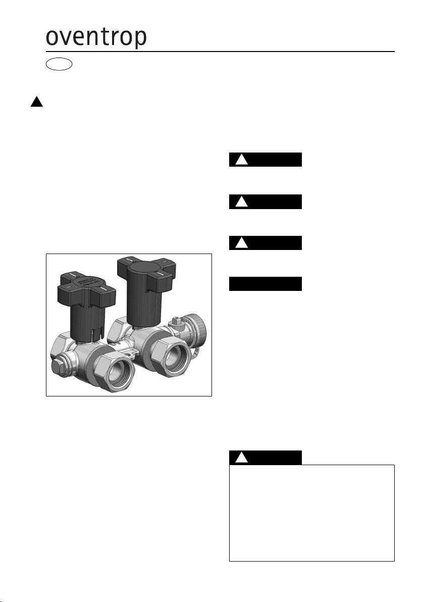
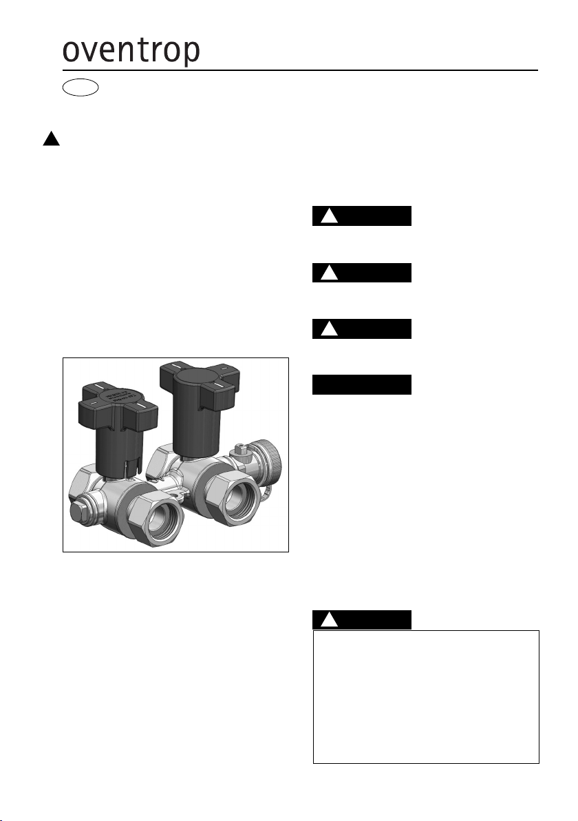
5 Aufbau und Funktion
5.1 Übersicht und Funktionsbeschreibung
Die Oventrop „Flypass 4TZ“ Anschlussarmatur wird zum Ab-
sperren, Spülen, Entleeren und Entlüften der in Durchströ-
mungsrichtung vorgeschalteten Vor- und Rücklaufleitung oder
der nachgeschalteten Anlagenteile eingesetzt. Sie ist zusätzlich
Umstellbar auf Bypassbetrieb. Die ugelstellungen und somit
die Durchflusswege der verbauten Dreiwegekugeln sind anhand
der Griffform ablesbar. Die Armatur ist mit zwei seitlich ange-
ordneten G 1/4 Zubehöranschlüssen zum Einschrauben von
Oventrop F+E – ugelhähnen (ein Hahn ist im Lieferumfang
enthalten) oder Messventilen aus dem „Hydrocontrol“ Pro-
gramm versehen. Die verlängerten Griffe ermöglichen eine Iso-
lierung der Armatur. Es stehen verschiedene Armaturen (Zube-
hör) zum direkten Anschluss an die „Flypass 4TZ“
Anschlussarmatur zur Verfügung.
5.2 Kennzeichnungen
Die Form der Handgriffe sowie die aufgedruckten Balken kenn-
zeichnen die Durchgangsbohrungen der eingebauten Dreiwe-
gekugeln und damit deren Schaltstellungen.
Angaben auf dem Gehäuse und ihre Bedeutung:
V ventrop
PN Nenndruck
6 Einbau
Die „Flypass 4TZ“ Anschlussarmatur wird für die Anbindung von
Gebläsekonvektoren (Fan-Coil), ühldeckenmodule, Induktions-
geräte, ühl- und Heizzonen usw. an das Rohrnetz von Zentral-
heizungs- und ühlanlagen mit geschlossenem reislauf einge-
baut. Sie kann beidseitig in beliebiger Durchströmungsrichtung
eingesetzt werden. Die Einbaulage ist beliebig (waagerecht,
schräg oder senkrecht, in steigende oder fallende Abschnitte).
Warnhinweise unter Abschnitt 2 (Sicherheitshin-
weise) beachten!
– Bei der Montage dürfen keine Fette oder Öle verwendet
werden, da diese die Dichtungen zerstören können.
Schmutzpartikel sowie Fett- und Ölreste sind ggf. aus
den Zuleitungen herauszuspülen.
– Bei der Auswahl des Betriebsmediums ist der allgemeine
Stand der Technik zu beachten (z. B. VDI 2035).
– Gegen äußere Gewalt (z. B. Schlag, Stoß, Vibration)
schützen.
Nach der Montage sind alle Montagestellen auf Dichtheit zu
überprüfen.
4 Technische Daten
4.1 Leistungsdaten
Max. Betriebstemperatur ts: +120°C
Min. Betriebstemperatur ts: –10°C
Max. Betriebsdruck ps: 1600 kPa
kvs Normalbetrieb DN15/20: 22/34
kvs Bypassbetrieb DN15/20: 1,2/1,25
Medium: Nicht aggressive Flüssigkeiten (z. B. Wasser und ge-
eignete Wasser-Glykolgemische gemäß VDI 2035). Nicht für
Dampf, ölhaltige und aggressive Medien geeignet.
4.2 Materialien
Gehäuse aus entzinkungsbeständigem Messing, Dichtungen
aus EPDM bzw. PTFE, Griffe aus Polyamid.
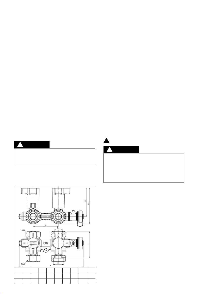
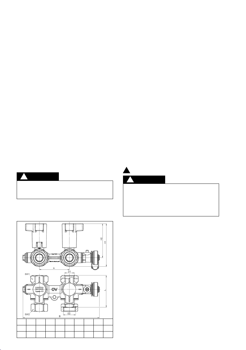
4.3 Abmessungen/Anschlussmaße
A H1H2SW1SW2D1D2B L
DN 15
65 93 74 34 32 G 1⁄2G 3⁄4166 68.5
DN 20
65 93 74 34 38 G 3⁄4G1 166 74
GEFAHR
!
7 Betrieb
7.1 Entlüftung der Anlage
Vor der Inbetriebnahme muss die Anlage aufgefüllt und entlüftet
werden. Dabei sind die zulässigen Betriebsdrücke zu beachten.
7.2 Korrekturfaktoren für Wasser-Glykol-Gemische
Die orrekturfaktoren der Frostschutzmittelhersteller müssen
ggf. berücksichtigt werden.
8 Zubehör
Das Zubehörsortiment finden Sie im atalog.
Für die Voreinstellung und Einregulierung der Wassermenge
bietet Oventrop zwei Messgeräte an:
– Oventrop „OV-DMC 2“-Messsystem
– Oventrop „OV-DMPC“-Messsystem
9 Wartung und Pflege
Die Armatur ist wartungsfrei.
Die Dichtheit und Funktion der Armatur und ihrer Verbindungs-
stellen ist im Rahmen der Anlagenwartung regelmäßig zu über-
prüfen. Eine gute Zugänglichkeit der Armatur wird empfohlen.
10 Gewährleistung
Es gelten die zum Zeitpunkt der Lieferung gültigen Gewähr-
leistungsbedingungen von Oventrop.
!
V RSICHT
!