2
2 Sicherheitshinweise
Der Vakuumröhrenkollektor ist zum Zeitpunkt seiner Ent-
wicklung nach geltenden, anerkannten Regeln der Tech-
nik entwickelt und hergestellt worden und gilt als
betriebssicher.
Es können durch die Anwendung von Kollektoren jedoch
Gefahren ausgehen, wenn das System von nicht fachge-
recht ausgebildeten Personen, unsachgemäß oder nicht
bestimmungsgemäß verwendet wird.
2.1 Bestimmungsgemäße Verwendung / Inbetrieb-
nahme
Die Betriebssicherheit ist nur bei bestimmungsgemäßer
Verwendung des Systems gewährleistet.
Die Montage und nbetriebnahme muss von einer Fach-
firma ausgeführt werden. Für die praktische Ausführung
gelten die einschlägigen Regeln der Technik und bei
allen Montagearbeiten auf dem Dach sind geeignete
Maßnahmen zum Unfallschutz zu treffen.
Jede darüber hinausgehende und/oder andersartige Ver-
wendung des Kollektors ist untersagt und gilt als nicht
bestimmungsgemäß. Ansprüche jeglicher Art gegen den
Hersteller und/oder seine Bevollmächtigten wegen Schä-
den aus nicht bestimmungs-gemäßer Verwendung des
Kollektors sind ausgeschlossen.
2.2 Personal
Die nstallation, Wartung und Reparatur darf nur von
qualifiziertem Fachpersonal durchgeführt werden.
WARNUNG!
Verletzungsgefahr bei unzureichender Qualifika-
tion!
Unsachgemäßer Umgang kann zu erheblichen Perso-
nen- und Sachschäden führen.
Deshalb:
- Alle Tätigkeiten nur durch die in dieser Anleitung
benannten Personen durchführen lassen.
Die Gas-, Wasserfachkraft ist aufgrund ihrer fachlichen
Ausbildung, Kenntnisse und Erfahrungen sowie Kenntnis
der einschlägigen Normen und Bestimmungen in der
Lage, Arbeiten an Heizungsanlagen (Solaranlagen) aus-
zuführen und mögliche Gefahren selbstständig zu erken-
nen.
Die Gas-, Wasserfachkraft ist speziell für das Arbeitsum-
feld, in dem sie tätig ist, ausgebildet und kennt die rele-
vanten Normen und Bestimmungen.
Die Elektrofachkraft ist aufgrund ihrer fachlichen Ausbil-
dung, Kenntnisse und Erfahrungen sowie Kenntnis der
einschlägigen Normen und Bestimmungen in der Lage,
Arbeiten an elektrischen Anlagen auszuführen und mög-
liche Gefahren selbstständig zu erkennen.
Die Elektrofachkraft ist speziell für das Arbeitsumfeld, in
dem sie tätig ist, ausgebildet und kennt die relevanten
Normen und Bestimmungen.
Die Dachdeckerfachkraft ist aufgrund ihrer fachlichen
Ausbildung, Kenntnisse und Erfahrungen sowie Kenntnis
der einschlägigen Normen und Bestimmungen in der
Lage, Arbeiten an Dachaufbauten / Dacheindeckungen
auszuführen und mögliche Gefahren selbstständig zu er-
kennen.
Die Dachdeckerfachkraft ist speziell für das Arbeitsum-
feld, in dem sie tätig ist, ausgebildet und kennt die rele-
vanten Normen und Bestimmungen.
2.3 Besondere Gefahren
Die hier aufgeführten Sicherheitshinweise und die Warn-
hinweise in den weiteren Kapiteln dieser Anleitung
beachten, um Gesundheitsgefahren zu reduzieren und
gefährliche Situationen zu vermeiden.
2.4 Mitgeltende Unterlagen
Neben dieser Betriebsanleitung für den Kollektor gelten
die im Folgenden aufgeführten Betriebsanleitungen der
gesamten Solaranlage. Die darin enthaltenen Hinweise -
insbesondere Sicherheitshinweise - unbedingt beachten!
• BDH nfoblätter Nr. 17 „Thermische Solaranlagen“ Teil
1, 2 und 3
• BDH nfoblätter Nr. 27 „Solare Heizungsunterstützung“
Teil 1 und 2
• BDH nfoblätter Nr. 49 „Ermittlung von Schneelasten“
• Bedienungsanleitung Pumpe
• Bedienungs- und Montageanleitung Regler
• Allgemeine Funktionsbeschreibung Regler
• Hydraulikschemen Regler
• Bedienungs- und nstallationsanleitung Speicher
• Bedienungs- und nstallationsanleitung Membranaus-
dehungsgefäß
• Bedienungs- und nstallationsanleitung sonstiger Kom-
ponenten der Heizungsanlage
• Weitere nformationen im nternet:
- www.oventrop.de
- www.bdh-koeln.de
2.5 Wichtige Normen, Vorschriften und EG-Richtlinien
für die Installation von Sonnenkollektoren
• DIN EN 12975-1 Thermische Solaranlagen und ihre Bau-
teile - Kollektoren - Teil 1: Allgemeine Anforderungen
• DIN EN 12976-1 Thermische Solaranlagen und ihre
Bauteile - Vorgefertigte Anlagen - Teil 1: Allgemeine
Anforderungen
• DIN V ENV 12977-1 Thermische Solaranlagen und ihre
Bauteile - Kundenspezifisch gefertigte Anlagen - Teil 1:
Allgemeine Anforderungen
• DIN 1055-4 Einwirkungen auf Tragwerke - Teil 4: Wind-
lasten
• DIN 1055-5 Einwirkungen auf Tragwerke - Teil 5:
Schnee- und Eislasten
• DIN 18421 Dämmarbeiten an technischen Anlagen
• DIN 18382 Elektrische Kabel- und Leitungsanlagen in
Gebäuden
• DIN VDE 0185 Blitzschutzanlagen
• DIN VDE 0100 Errichten von Starkstromanlagen bis
1000 V
Die geltenden Normen und Richtlinien sind zu beachten.
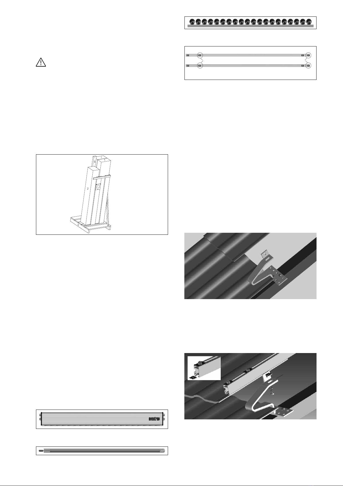
3 Transport und Handhabung
Die Vakuumröhren sind erst auszupacken und zu
installieren, wenn alle anderen Montagen durchgeführt
sind und das System gefüllt und betriebsbereit ist. Vaku-
umröhren auch vor der Montage gegen Sonneneinstrah-
lung schützen. Vakuumröhren ohne Wärmeabnahme
können im Bereich der Heat-Pipe (Kondensator) in weni-
gen Minuten Temperaturen von über 100°C erreichen.
Röhren- und Sammlerverpackungseinheiten sind
senkrecht zu transportieren. Beim Öffnen der Kartonagen
keine scharfkantige Gegenstände verwenden. Beim
Transport muss darauf geachtet werden, dass keine
anderen Gegenstände auf den Röhren- oder Sammler-
verpackungseinheiten abgestellt werden.
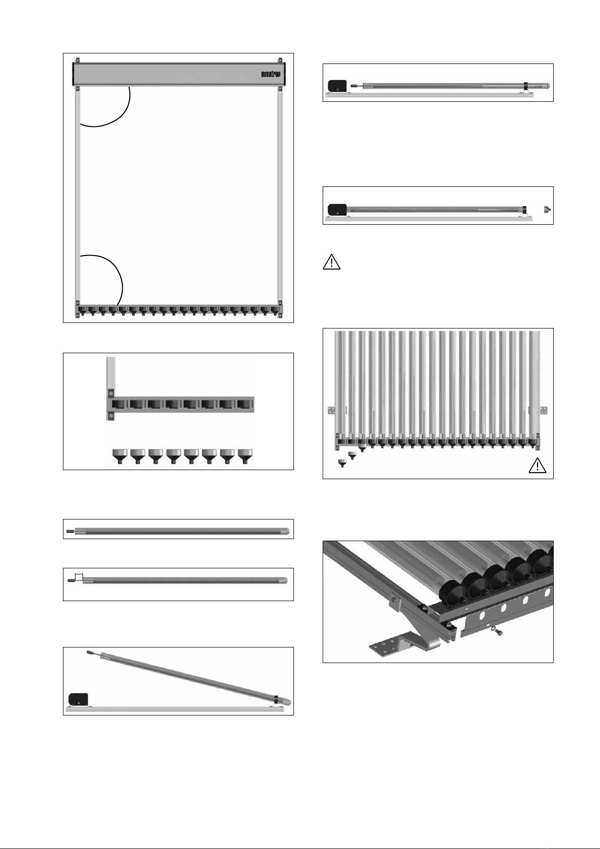
Bei nstallation darf der Kollektor nicht direkt der
Sonneneinstrahlung ausgesetzt werden. Um Langzeit-
schäden auszuschließen sind die Vakuumröhren nach
der Montage entweder abzudecken und vor Sonnenein-
strahlung zu schützen oder die Solaranlage muss vor der
Röhrenmontage befüllt werden. Kollektoren ohne Wär-
meabnahme können im Bereich der Kollektoranschlüsse
nach Montage der Vakuumröhren in wenigen Minuten
Temperaturen von über 100°C erreichen.
Die hochselektive Absorberbeschichtung hat optische Unre-
gelmäßigkeiten (blau bis schwarz schimmern e Oberfläche)
im Erscheinungsbil . Abhängig vom Betrachtungswinkel kann
!