16
2 Safety notes
At the time of its development, the flat-plate collector was designed
and manufactured according to the valid, approved rules of tech-
nology and is of high functional reliability.
The application of the collector may, however, involve certain dan-
gers if it is not used properly or correctly.
2.1 Correct use / Initial operation
The safety in operation is only guaranteed if the collector is used
correctly.
Installation and initial operation may only be carried out by a qual-
ified tradesman. The approved rules of technology are valid for
practical use and suitable measures for the prevention of accidents
have to be taken during installation on the roof.
Any other use of the collector is prohibited and not compliant.
Claims against the manufacturer and/or his authorized represen-
tatives regarding damages resulting from incorrect use of the col-
lector will not be accepted.
2.2 Personnel
Installation, maintenance and repair may only be carried out by a
qualified tradesman.
WARNING!
Risk of injury!
Improper use may lead to extensive injuries to persons and
damage to property.
or this reason:
– Any work may only be carried out by qualified persons.
Due to his professional training, knowledge and experience as
well as his knowledge of the relevant standards and regulations,
the qualified gas and water specialist is in a position to carry
out any work at heating installations (solar plants) and to recognize
possible dangers.
Due to his professional training, knowledge and experience as
well as his knowledge of the relevant standards and regulations,
the qualified electrician is in a position to carry out any work at
electrical installations and to recognize possible dangers.
Due to his professional training, knowledge and experience as
well as his knowledge of the relevant standards and regulations,
the qualified roofer is in a position to carry out any work at the
roof construction/roofing and to recognize possible dangers.
2.3 Specific risks
The safety notes shown here as well as the warning notes in other
chapters of the instructions are to be observed in order to reduce
health risks and avoid dangerous situations.
2.4 Other valid documents
Apart from the operating instructions for the collector, the below
mentioned operating instructions of the complete solar plant should
be observed. Notes including these instructions – especially the
safety notes – must be observed!
• BDH information sheet no. 17 “Thermal solar plants” parts 1, 2
and 3
• BDH information sheet no. 27 “Solar heating support“ parts 1
and 2
• Pump operating instructions
• Controller operating and installation instructions
• Controller general functional description
• Controller hydronic schemes
• Storage cylinder operating and installation instructions
• Diaphragm expansion tank operating and installation instructions
• Operating and installation instructions of other components of
the heating system
• Or country specific rules and regulations
• urther information on the internet:
- www.oventrop.de
- www.bdh-koeln.de
2.5 Important standards, rules and EC directives for the
installation of solar collectors
• DIN EN 12975-1 Thermal solar plants and their
components – Collectors – Part 1: General specification
• DIN EN 12976-1 Thermal solar plants and their
components – Preassembled plants – Part 1:
General specification
• DIN V ENV 12977-1 Thermal solar plants and their
components – Customized plants – Part 1:
General specification
• DIN 1055-4 Impacts on structural framework – Part 4:
Wind load stressing
• DIN 1055-5 Impacts on structural framework – Part 5:
Snow and ice load stressing
• DIN 18421 Insulation of technical plants
• DIN 18338 Roof tiling and roof insulation work
• DIN 18339 Plumbing
• DIN 18382 Electrical cabling in buildings
• DIN VDE 0185 Lightning protection plants
• DIN VDE 0100 Installation of power plants up to 1000V
Current standards and guidelines must be observed.
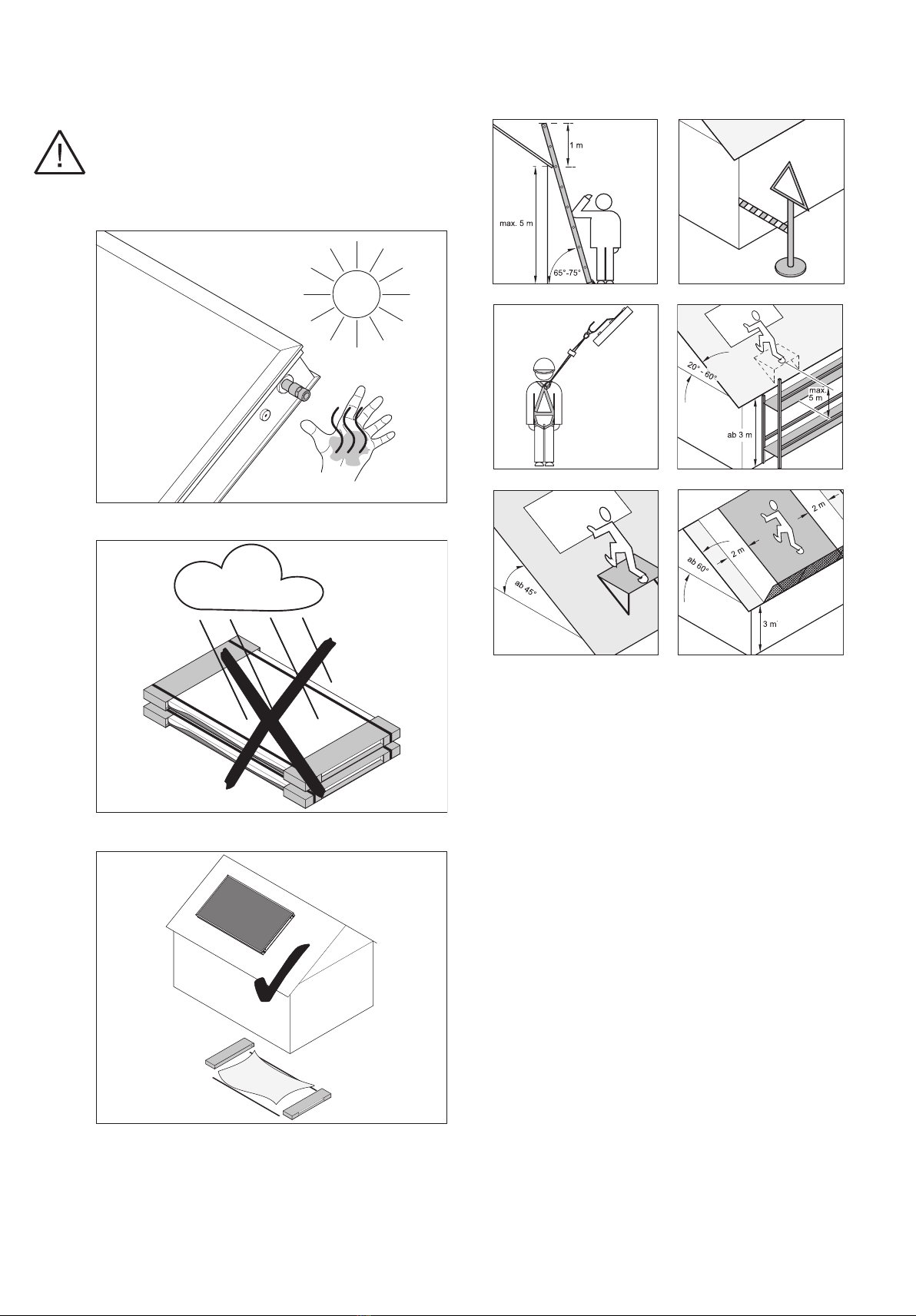
3 Transport and handling
• Information regarding storage of collectors in open air
Lay down collectors with the pane facing upwards. Do not cover
the collectors in open air! Condensation water (e.g. under a foil)
may cause glass corrosion. Avoid direct ground contact (put
timber beams underneath). Avoid scratches on the panes by
separating the collectors with spacers (e.g. wood battens). When
leaning the collectors against walls or similar, please keep a
minimum inclination angle of 15° and use spacers. Do not use
cardboard as intermediate layer. In case of improper storage,
humidity may penetrate through the vent holes.
• Range and limits of application
The collector is designed for use in thermal solar installations
for hot water supply and support of the heating system. Water
(Attention: Risk of frost!) or a water and glycol mixture are to be
used as operating medium in a closed circuit. Operational con-
ditions leading to a long-term reduction of the dew point in the
collector are inadmissible. This can be the case if collectors are
directly integrated into the solar circuit of a heat pump.
• Thermal protection
To avoid damage to the solar circuit, the technical information
“Thermal protection” must be observed for installations with 4
or more OK collectors with antireflective glass as well as for
central roof heating.
• Frost damage
Collectors cannot be drained off completely after having pres-
surised and flushed the system. Do not leave pure water in the
collector where it will be exposed to frost!
• Mounted, empty collector
Completed mounted and unfilled collectors must only be ex-
posed to the sun for a few days to avoid damage to the seals.
Alternatively only install seals before filling.
• Diffusion of vapour for integrated roof installations
With roof integration, the area below the collector field must be
protected from rising humidity and airlocks (foil with vapour dif-
fusion barrier, sufficient aeration of the roof underneath the col-
lectors).
• Disposal:
The collector contains harzardous waste. Dismounted collectors
can be returned to the manufacturer Oventrop. They will be dis-
posed of professionally.