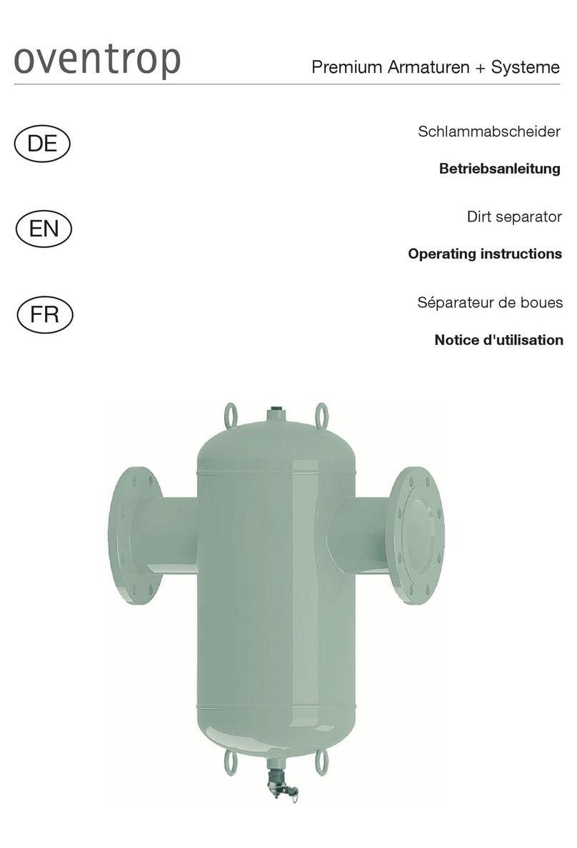
oventrop Toc-Duo-3 Operating instructions

Premium Armaturen + Systeme
„Toc-Duo-3“ Heizölfilter-Entlüfter-Kombination
Einbau- und Betriebsanleitung für Fachpersonal
Vor dem Einbau der Armatur die Einbau- und Be-
triebsanleitung vollständig lesen!
Einbau, Inbetriebnahme, Bedienung und Wartung
darf nur durch geschultes Fachpersonal durchge-
führt werden!
Die Einbau- und Betriebsanleitung sowie alle mit-
geltenden Unterlagen sind an den Anlagenbetreiber
weiterzugeben!
Inhalt:
1 Allgemeine Hinweise ...................................... 1
2 Sicherheitshinweise........................................ 2
3 Transport, Lagerung und Verpackung ............ 2
4 Technische Daten ........................................... 2
5 Aufbau und Funktion ...................................... 3
6 Einbau ............................................................ 3
7 Betrieb ........................................................... 6
8 Zubehör ......................................................... 6
9 Wartung und Pflege........................................ 6
10 ewährleistung............................................... 6
DE
Technische Änderungen vorbehalten.
214276180 12/2016
OVENTROP mbH & Co. K
Paul-Oventrop-Straße 1
D-59939 Olsberg
Telefon +49 (0)2962 82-0
Telefax +49 (0)2962 82-400
E-Mail mail@oventrop.de
Internet www.oventrop.com
Eine Übersicht der weltweiten Ansprechpartner
finden Sie unter www.oventrop.de.
Abb. 1.1 „Toc-Duo-3“ Heizölfilter-Entlüfter-Kombination
!
ACHTUN weist auf mögli-
che Sachschäden hin, welche entstehen können, wenn
die Sicherheitsmaßnahmen nicht befolgt werden.
VORSICHT weist auf eine
möglicherweise gefährliche Situation hin, die zu gering-
fügigen oder leichten Verletzungen führen kann, wenn
die Sicherheitsmaßnahmen nicht befolgt werden.
V RSICHT
!
1 Allgemeine Hinweise
1.1 Informationen zur Einbau- und Betriebsanleitung
Diese Einbau- und Betriebsanleitung dient dem ge-
schulten Fachpersonal dazu, die Armatur fachgerecht
zu installieren und in Betrieb zu nehmen.
Mitgeltende Unterlagen – Anleitungen aller Anlagen-
komponenten sowie geltende technische Regeln –
sind einzuhalten.
1.2 Aufbewahrung der Unterlagen
Diese Einbau- und Betriebsanleitung ist vom Anlagen-
betreiber zum späteren ebrauch aufzubewahren.
1.3 Urheberschutz
Die Einbau- und Betriebsanleitung ist urheberrechtlich
geschützt.
1.4 Symbolerklärung
Hinweise zur Sicherheit sind durch Symbole gekenn-
zeichnet. Diese Hinweise sind zu befolgen, um Unfälle,
Sachschäden und Störungen zu vermeiden.
ACHTUNG
eprüft durch
TÜV Rheinland
Reg.-Nr.: 2 Y 112/09

2
3 Transport, Lagerung und
Verpackung
3.1 Transportinspektion
Lieferung unmittelbar nach Erhalt sowie vor Einbau
auf mögliche Transportschäden und Vollständigkeit
untersuchen.
Falls derartige oder andere Mängel feststellbar sind,
Warensendung nur unter Vorbehalt annehmen. Rekla-
mation einleiten. Dabei Reklamationsfristen beachten.
3.2 Lagerung
Die Armatur nur unter folgenden Bedingungen lagern:
– Nicht im Freien. Trocken und staubfrei aufbewah-
ren.
4 Technische Daten
4.1 Leistungsdaten
Max. Umgebungstemperatur: + 60°C *
Max. Betriebstemperatur ts: + 60°C *,
Metallausführung
+ 70°C *
Min. Betriebstemperatur ts: 0°C
Max. Betriebsdruck ps: max. 0,7 bar, entspre-
chend 8m statischer
Ölsäule bei höher lie-
gendem Tank.
Düsenleistung: bis max. 110 l/h
Rücklaufstrom: bis max. 120 l/h
Entlüftungsleistung: min. 6 l/h Luft bzw.
Ausgasungen
Saugdruck: max. -0,5 bar
Prüfdruck: max. 6 bar
TÜV-geprüft: TÜV-Rheinland,
Nr.: S138 2014 ES
* nach DIN 4755 ist 40 °C die max. zulässige Tempe-
ratur des Heizöls in Ölleitungen von Ölfeuerungsanla-
gen
Scharfe Kanten!
Verletzungsgefahr! Nur mit geeigneten Schutz-
handschuhen anfassen. ewinde, Bohrungen und
Ecken sind scharfkantig.
Kleinteile!
Verschluckungsgefahr! Armatur nicht in Reich-
weite von Kindern lagern und installieren.
Allergien!
Gesundheitsgefahr! Armatur nicht berühren und
jeglichen Kontakt vermeiden, falls Allergien gegen-
über den verwendeten Materialien bekannt sind.
VRSICHT
!
2.2 Gefahren, die vom Einsatzort und Transport
ausgehen können
– Armatur gegen äußere ewalt (z. B. Schlag, Stoß)
schützen.
– Heizöle sind wassergefährdende
Stoffe, die bei Wartungsarbeiten
aufgefangen werden müssen. Die
entsprechenden esetze und Ver-
ordnungen sind einzuhalten.
ACHTUNG
Druckverlust ∆p [mbar]
·
Durchfluss V [l/h]
Durchflussdiagramm:
Druckverlust im Saugbetrieb (für Heizöl EL)
Druckverlust ∆p [mbar]
Der Fall eines externen Brandes wurde bei der Ausle-
gung der Armatur nicht berücksichtigt.
2 Sicherheitshinweise
2.1 Bestimmungsgemäße Verwendung
Die Betriebssicherheit ist nur bei bestimmungsgemä-
ßer Verwendung der Armatur gewährleistet.
Die Oventrop „Toc-Duo-3“ Heizölfilter-Entlüfter-Kom-
bination eignet sich ausschließlich für den Einsatz im
Einstrangsystem mit Rücklaufzuführung im Saugbe-
trieb.
Jede darüber hinausgehende und/oder andersartige
Verwendung der Armatur ist untersagt und gilt als
nicht bestimmungsgemäß. Ansprüche jeglicher Art
gegen den Hersteller und/oder seine Bevollmächtigten
wegen Schäden aus nicht bestimmungsgemäßer Ver-
wendung können nicht anerkannt werden.
Zur bestimmungsgemäßen Verwendung zählt auch
die korrekte Einhaltung der Einbau- und Betriebsan-
leitung.
– Keinen aggressiven Medien oder Hitzequellen aus-
setzen.
– Vor Sonneneinstrahlung und übermäßiger mecha-
nischer Erschütterung schützen.
– Lagertemperatur: –20°C bis +60°C,
relative Luftfeuchtigkeit: max. 95 %
3.3 Verpackung
Sämtliches Verpackungsmaterial ist umweltgerecht zu
entsorgen.

3
5 Aufbau und Funktion
5.1 Übersicht und Funktionsbeschreibung
Oventrop „Toc-Duo-3“ Heizölfilter-Entlüfter-Kombina-
tion zur Filterung und automatischen Entlüftung des
Heizöls. Die Brennerpumpe saugt über die Saugleitung
das Öl durch Absperrventil, Filter und Rückschlagventil
an. Der Filter hält Schmutzpartikel zurück. Ein in der
Regel kleiner Teil des Öls wird von der Brennerpumpe
zur Düse gepumpt und verbrannt (je 10 kW Heizleis-
tung ca. 1 Liter Öl pro Stunde). Der Überschuss wird
durch die Rücklaufleitung zum Entlüfterteil geführt.
Luft und Ausgasungen steigen auf und werden über
ein Schwimmerventil an die Atmosphäre abgeführt.
Das entlüftete Öl wird über ein Überströmventil dem
Vorlauf wieder zugeführt; dadurch wird nur die ver-
brauchte Menge über Saugleitung und Filter aus dem
Tank gesaugt. leichzeitig wird die Arbeitswärme der
Medium:
Heizöl EL nach DIN 51603-1, und Heizöle mit „alter-
nativen“ Anteilen bis zu 20% Bio-Anteil, z.B. Heizöl
EL A Bio 20 nach DIN SPEC 51603-6.
Der „Toc-Duo-3“ Metallausführung Art.-Nr. 2152754
ist auch für Heizöle mit bis zu 100% „alternativen“
Anteilen, dünnflüssige Pflanzenöle sowie FAME nach
EN 14214 geeignet.
4.2 Materialien
Entlüftergehäuse aus Metall, mit Halterung für Wand-
montage und Absperrventil. Filtertasse und Entlüfter-
haube aus transparentem Kunststoff, bei Artikel-Nr.
2152754 aus Metall.
4.3 Abmessungen/Anschlussmaße
(* Maß bei I = 163 mm,
** “opticlean“ lang = 193 mm)
Anschlüsse
Tankseite: 3⁄8Innengewinde
Brennerseite: 3⁄8 Außengewinde mit Konus für
Brennerschläuche oder ¼ Innen-
gewinde
Funktionsschema:
6 Einbau
Eine gute Zugänglichkeit der Armatur wird empfohlen.
Für Wartung und Überwachung ist der „Toc-Duo-3“
an gut sichtbarer und zugänglicher Stelle zu installie-
ren.
Die Einbaulage ist senkrecht mit der Entlüfterhaube
nach oben. Die Durchflussrichtung – siehe Kennzeich-
nung auf dem ehäuse - ist zu beachten.
Kappe
Absperr-
hahn
vom
Tank
Kugelrück-
schlagventil
Filtereinsatz
Filtertasse
Sicherheits-
Schwimmer
Schwimmer
Überström-
Ventil
Rücklauf
Vorlauf
Manometer
Rücklauf
vom
Brenner
Vorlauf
zum
Brenner
Halteplatte
rechts
oder links
Ölpumpe zum Vorwärmen des Öles benutzt. Im Betrieb
wird sich ein relativ konstanter Füllstand im unteren
Teil der Entlüfterhaube einstellen. Dieser Teil kann sich
je nach Betriebsbedingungen auch ganz füllen.
elangt Heizöl in den oberen Teil mit dem Sicherheits-
schwimmer, so ist der „Toc-Duo-3“ auszutauschen.

4
Warnhinweise unter Abschnitt 2 (Sicherheits-
hinweise) beachten!
!
Die Heizölfilter-Entlüfter-Kombination ist mit Hilfe der
beiliegenden Befestigungsplatte an geeigneter Stelle
zu montieren. Sie kann oberhalb oder unterhalb des
Tankspiegels eingebaut werden. Zur Montage an der
Kesselwand liegen Blechschrauben bei.
Die Ölleitungen müssen frostfrei installiert und betrie-
ben werden, da Öl bei niedrigen Temperaturen Paraf-
fine ausscheidet, wodurch die Filter verstopfen können.
Dies gilt umso mehr, je feiner der Filtereinsatz ist.
Bei Umrüstung von Zweistranganlagen auf den Ein-
strangbetrieb ist ggf. die Leitungsdimension zu redu-
zieren, siehe „Dimensionierung der Saugleitung“.
– Armatur gegen äußere ewalt (z. B. Schlag, Stoß,
Vibration) schützen.
– Der Vor- und Rücklaufanschluss darf nicht ver-
tauscht montiert werden, da dies zu Schäden an
Entlüfter und Brennerpumpe führen kann.
– Es ist darauf zu achten, dass die Umgebungs-
temperatur max. 60°C nicht übersteigt, d.h. nicht
in der Nähe eines unisolierten Kesselteils oder
des Abgasrohres, sowie nicht über zu öffnenden
Klappen der Feuerung montieren.
– Hinweis:
Aus technischen ründen sind ölgefüllte Entlüfter
nicht stark zu neigen oder abzulegen. Bitte das
Öl erst auslaufen lassen.
ACHTUNG
Nach der Montage sind alle Montagestellen auf Dicht-
heit zu überprüfen.
Wenn die baulichen egebenheiten es gestatten, sollte
die Leitung als „selbstüberwachende Saugleitung“
ausgeführt sein. Sie ist dann mit stetigem efälle zum
Tank hin zu verlegen und alle Rückschlagventile vor
dem „Toc-Duo-3“ sind zu entfernen. Bei Undichtig-
keiten reißt dann die Ölsäule in der efällstrecke ab..
Einbaubeispiele:
Installation des „Toc-Duo-3“ unterhalb des Ölspiegels.
Installation des „Toc-Duo-3“ oberhalb des Ölspiegels.
Druckprüfung:
Bei der Druckprüfung der Saugleitung ist der Druck-
anschluss nicht am „Toc-Duo-3“ vorzunehmen, da das
integrierte Rückschlagventil die Druckübertragung zur
Tankseite verhindert.
Die Schwimmerventile eines neuen, ungefüllten „Toc-
Duo-3“ sind außerdem geöffnet, sodass er nicht in die
Druckprüfung mit einzubeziehen ist.
Dimensionierung der Saugleitung:
Die Saugleitung zum Tank sollte so dimensioniert wer-
den, dass die Strömungsgeschwindigkeit des Heizöls
während des Brennerbetriebes zwischen 0,2 bis 0,5
m/s beträgt (DIN 4755). Dies gilt besonders für Rohr-
abschnitte die nach unten führen. Durch eine zu große
Saugleitung wird die Fließgeschwindigkeit sehr gering,
sodass die Ausgasungen nicht gleichmäßig mitgeför-
dert werden und sich zu großen Luftblasen in oben
liegenden Leitungsabschnitten ansammeln. Wenn eine
große Luftblase zur Brennerpumpe gelangt, kann sie
zu Störungen führen. Für kleine Brennereinheiten in
Ein- und Zweifamilienhäusern reicht oft der Rohrin-
nendurchmesser 4 mm aus (z.B. Rohr 6 x 1). Neben
der Fließgeschwindigkeit sind der Strömungswider-
stand und die Saughöhe zu berücksichtigen.
„Toc-Duo-3“
Brenner
„Toc-Duo-3“
Brenner
Erdtank

5
Nomogramm:
Strömungsgeschwindigkeit des Heizöls
während des Betriebs nach DIN 4755:
0.2 bis 0.5 m/s
*Rohrinnendurchmesser unter 4 mm
vermeiden
Beispiele:
a) Für eine Fördermenge von 30 l/h (ca. 300 kW) wird
bei einer mittleren Sauggeschwindigkeit von 0,3 m/s
eine Rohrleitung von 8 x 1 mit lichter Weite 6 mm
benötigt.
b) Eine kleine Anlage mit 30 kW Heizleistung, entspre-
chend 3 l/h Durchflussmenge, wird mit der Leitungs-
dimension 6 x 1 (lichte Weite 4 mm) ausgestattet.
Die Strömungsgeschwindigkeit ist dann zwar sehr
niedrig (ca. 0,07 m/s), jedoch sind mögliche Luftan-
sammlungen sehr klein und führen nicht zu Störun-
gen.
Saug- und Druckbetrieb
Die Heizölfilter-Entlüfter-Kombination darf nicht im
Druckbetrieb, d.h. hinter einer Förderpumpe in der
Vorlaufleitung eingesetzt werden. Dies ist auch nicht
sinnvoll, da Luftanteile nur im Saugbetrieb aus dem
Heizöl ausgeschieden werden. Es muss gemäß der
DIN 4755 sichergestellt sein, dass in geschlossenen
Leitungsabschnitten Druckerhöhungen durch Tempe-
raturanstieg des Heizöls ausgeglichen werden (z.B.
durch Installation einer Druckausgleichseinrichtung).
Alternativ kann man abgeschlossene Leitungsab-
schnitte vermeiden durch Verzicht auf Rückschlag-
ventile. Druckerhöhungen können zu Schäden an Ent-
lüftern und anderen Bauteilen führen.
Luftansammlung in der Filtertasse:
Da das Öl vor der Entlüftung zunächst gefiltert wird,
kann die aus dem Heizöl ausgeschiedene Luft vom
ölbenetzten Filtereinsatz zurückgehalten werden, so-
dass sich in der Filtertasse vor dem Filtereinsatz (1)
ein Luftpolster bildet.
Dieses Luftpolster stört den Anlagenbetrieb nicht, da
der Filtereinsatz innen gefüllt ist. Dies lässt sich ins-
besondere da beobachten, wo große Luftanteile vom
Öl mitgeführt werden, oder nur kleine Mengen an Öl
verbraucht werden
(10 kW ~ 1 lÖl/h). Der Ölspiegel kann auch beim Bren-
nerbetrieb etwas absinken.
Füllstand in der Entlüfterhaube:
Je nach Betriebszustand können sich im unteren Teil
der Entlüfterhaube (2) unterschiedliche Füllstände ein-
stellen.
Diese Kammer kann auch ganz gefüllt werden, z.B.
wenn bei höher liegendem Tank keine Ausgasungen
vorliegen, kann sich die vorhandene Luft im Kreislauf
zwischen Brennerpumpe und Entlüfterkammer im
Heizöl auflösen.
Ändern sich die Betriebsbedingungen, z.B. durch einen
sinkenden Ölstand im Tank, kann sich ein neues Luft-
polster bilden.
Befindet sich Heizöl in dem oberen Teil (3) mit dem Si-
cherheitsschwimmer, so ist die Armatur auszutau-
schen.
Parallelinstallation von mehreren „Toc-Duo-3“
Wenn größere Düsenleistungen als 110 l/h benötigt
werden, können zwei oder auch mehrere Entlüfter pa-
rallel installiert werden. Es ist hierbei zu beachten,
dass der maximale Rücklaufstrom von 120 l/h pro an-
geschlossenem Entlüfter nicht überschritten wird. Der
Rücklaufstrom ist die Fördermenge der Pumpe, ver-
mindert um die verbrannte Ölmenge.
Öldurchsatz
in l/h Rohrinnen-Ø
in mm
Strömungs-
geschwindig-
keit in m/s
min.

6
9 Wartung und Pflege
Die Dichtheit und Funktion der Armatur und ihrer Ver-
bindungsstellen ist im Rahmen der Anlagenwartung
regelmäßig zu überprüfen.
Die Filtereinsätze sind nicht zu reinigen. Sie sollten vor
jeder Heizperiode ausgetauscht werden.
7 Betrieb
7.1 Entlüftung der Anlage
Vor der Inbetriebnahme muss die Anlage aufgefüllt
und entlüftet werden. Dabei sind die zulässigen Be-
triebsdrücke zu berücksichtigen.
7.2 Ölgeruch:
Der Entlüfter gibt Ausgasungen an die Atmosphäre
ab. Dadurch kann es zu eruchsbelästigungen in
schlecht belüfteten Heizräumen kommen. In diesen
Fällen kann über einen Schlauchnippel ein Schlauch
aufgesteckt und die Luft abgeführt werden (siehe Zu-
behör). Es ist dafür zu sorgen, dass der Schlauch nicht
verschlossen wird.
8 Zubehör Art.-Nr.
O-Ring zur Abdichtung Filtertasse / Filterkopf
2166500
Überwurfmutter 2126600
Klarsicht Filtertasse Standard 2126751
Klarsicht Filtertasse für „Magnum“ 2126755
Klarsicht Filtertasse für „opticlean“ lang 2126774
Metall Filtertasse 2126754
Halterung mit Schrauben 2142792
Schlauchtülle mit 10 m Schlauch 2142990
Filtereinsatz Siku 50 - 75 μm 2126300
Filtereinsatz Siku 25 - 40 μm (rotes Bajonett)
2126354
Filtereinsatz Siku 50 - 75 μm „Magnum“ 2126355
Filtereinsatz Siku 25 - 40 μm „Magnum“ 2126371
(rotes Bajonett)
Filtereinsatz „opticlean“ 5 - 20 μm 2126454
Filtereinsatz „opticlean“ lang 5 - 20 μm 2126474
Filtereinsatz „opticlean“ lang ~ 2 μm 2126484
„Ofix-Oil“ Klemmringverschraubungen
für den Anschluss von Kupferrohr an den tankseitigen
Eingang:
Anschlusssatz (einfach)
6 mm 2127650
8 mm 2127651
10 mm 2127652
12 mm 2127653
Messing-Stützhülsen für Kupferrohr mit 1 mm Wand-
stärke
6 mm 2083951
8 mm 2083952
10 mm 1029651
12 mm 1029652
Das Zubehörsortiment finden Sie im Katalog.
10 Gewährleistung
Es gelten die zum Zeitpunkt der Lieferung gültigen
ewährleistungsbedingungen von Oventrop.
Alkohol- oder lösungsmittelhaltige Reiniger dürfen
nicht verwendet werden, da sie die Kunststoffteile
schädigen können (andere Begriffe für Alkohol sind
z. B. Spirititus, Weingeist, Ethanol, u.a.).
ACHTUNG
Überschwemmung:
Die Oventrop „Toc-Duo-3“ Heizölfilter-Entlüfter-Kom-
bination kann auch in überschwemmungsgefährdeten
ebieten bis zu einer Überschwemmungshöhe von 5
m eingesetzt werden.
Da Schmutz die Entlüftungsbohrung verschließen und
somit zu späteren Funktionsstörungen führen kann,
wird der Austausch nach einer Überflutung des Bau-
teils empfohlen.

7
Valves, controls + systems
“Toc-Duo-3” Heating oil filter with deaerator
Installation and operating instructions for the specialised installer
Read installation and operating instructions in their
entirety before installing the heating oil filter with
deaerator!
Installation, initial operation, operation and main-
tenance must only be carried out by qualified tra-
desmen!
The installation and operating instructions, as well
as other valid documents must remain with the
user of the system!
Content:
1 eneral information......................................... 7
2 Safety notes .................................................... 8
3 Transport, storage and packaging .................. 8
4 Technical data ................................................. 8
5 Construction and function............................... 9
6 Installation ...................................................... 9
7 Operation ..................................................... 12
8 Accessories................................................... 12
9 Maintenance.................................................. 12
10 Warranty ........................................................ 12
EN
Subject to technical modification without notice.
214276180 12/2016
For an overview of our global presence visit
www.oventrop.com.
Illustr. 1.1 “Toc-Duo-3” Heating oil filter with deaerator
!
NOTICE indicates a possible
damage to property which may occur if the safety gui-
delines are not observed.
CAUTION indicates a possi-
ble dangerous situation which may lead to minor or
moderate injury if the safety guidelines are not obser-
ved.
CAUTI N
!
1 General information
1.1 Information regarding installation and opera-
ting instructions
These installation and operating instructions serve
the installer to install the heating oil filter with deaerator
professionally and to put it into operation.
Other valid documents – manuals of all system com-
ponents as well as valid technical rules – must be ob-
served.
1.2 Keeping of documents
These installation and operating instructions should
be kept by the user of the system.
1.3 Copyright
The installation and operating instructions are copy-
righted.
1.4 Symbol explanation
Safety guidelines are displayed by symbols. These
guidelines are to be observed to avoid accidents, da-
mage to property and malfunctions.
NOTICE

8
3 Transport, storage and
packaging
3.1 Transport inspection
Upon receipt check delivery for any damages caused
during transit.
Any damage must be reported immediately upon re-
ceipt.
3.2 Storage
The “Toc-Duo-3” must only be stored under the follo-
wing conditions:
– Do not store in open air, keep dry and free from
dust.
– Do not expose to aggressive fluids or heat sources.
4 Technical data
4.1 Performance data
Max. ambient temperature: + 60°C *
Max. operating temperature ts: + 60°C *,
metal model
+ 70°C *
Min. operating temperature ts: 0°C
Max. operating pressure ps: 0.7 bar, correspon-
ding to a static co-
lumn of oil of 8 m for
tanks located at a
higher level
Max. nozzle capacity: up to 110 l/h
Max. flow of returned
heating oil: up to 120 l/h
Min. deaeration capacity: 6 l/h air or gas
emissions
Max. suction pressure: -0.5 bar
Max. test pressure: 6 bar
TÜV tested: TÜV-Rhineland,
no.: S138 2014 ES
* According to DIN 4755, the max. admissible tem-
perature of heating oil in heating oil installations is
40°C
Sharp edges!
Risk of injury! Only touch with safety gloves. Threads,
bore holes and edges are sharp.
Small components!
Risk of ingestion! Store and install the heating oil
filter with deaerator out of reach of children.
Allergies!
Health hazard! Do not touch the heating oil filter
with deaerator and avoid any contact if allergies
against the used materials are known.
CAUTIN
!
2.2 Possible dangers at the installation location
and during transport
– Please protect the “Toc-Duo-3” against external
forces (e.g. impacts, vibrations
etc.).
– Heating oils are substances which
may pollute water. They must be
collected during maintenance
work. The corresponding laws and
decrees must be observed.
NOTICE
Pressure loss ∆p [mbar]
·
Flow rate V [l/h]
Flow chart:
Pressure loss during suction (for EL type of heating
oil)
Pressure loss ∆p [mbar]
The case of an external fire has not been taken into
consideration when constructing the heating oil filter
with deaerator.
2 Safety notes
2.1 Correct use
Safety in operation is only guaranteed if the heating
oil filter with deaerator is used correctly.
The Oventrop heating oil filter with deaerator “Toc-
Duo-3” can only be used in suction operated one
pipe systems with return flow feed.
Any use of the “Toc-Duo-3” outside the above appli-
cations will be considered as non-compliant and mi-
suse. Claims of any kind against the manufacturer
and/or his authorised representatives due to damages
caused by incorrect use cannot be accepted.
The observance of the installation and operating in-
structions is part of the compliance terms.
– Protect from direct sunlight and mechanical agita-
tion.
– Storage temperature: –20°C up to +60°C,
max. relative humidity of air: 95 %
3.3 Packaging
Packaging material is to be disposed of environmen-
tally friendly.

9
5 Construction and function
5.1 Summary and functional description
Oventrop heating oil filter with deaerator “Toc-Duo-3”
for filtering and automatic deaeration of heating oil.
The burner pump draws oil through the suction pipe
via the isolating valve, the filter and the check valve.
The filter retains dirt particles. Normally, a small pro-
portion of oil is pumped to the nozzle by the burner
pump and is burnt (per 10 kW of heat output about 1
litre of oil per hour). The excess is fed into the deaerator
via the return pipe. Air and gas emissions rise and are
expelled into the atmosphere via the float valve. The
deaerated oil is fed into the supply via the pressure
relief valve. As a result, only the used quantity is drawn
from the tank via the suction pipe and the filter. At the
same time, the working temperature of the oil pump is
used for pre-warming the oil. Under working conditi-
Fluid:
EL type of heating oil according to DIN 51603-1, and
heating oils with “alternative additives” with a bio pro-
portion up to 20%, e.g. EL A Bio 20 type of heating oil
according to DIN SPEC 51603-6.
The “Toc-Duo 3” metal model, item no. 2152754, is
also suitable for heating oils with “alternative additives”
up to 100%, thin vegetable oils as well as FAME ac-
cording to EN 14214.
4.2 Materials
Deaerator body made of metal, with wall bracket and iso-
lating valve. Filter cup and deaerator cap made of trans-
parent plastic, for item no. 2152754 made of metal.
4.3 Dimensions/Connection sizes
(* Dimension for female thread = 163 mm,
** “opticlean“ long = 193 mm)
Connections
Tank side: 3⁄8female thread
Burner side: 3⁄8 outer thread with taper for
burner hoses or ¼ female thread
Functional scheme:
6 Installation
For maintenance and monitoring, the “Toc-Duo-3”
should be installed in a prominent position which is
easily accessible.
The heating oil filter with deaerator is to be installed
vertically with the deaerator cap pointing upwards.
The direction of flow – see marking on the body –
must be observed.
Cap
Isolating
valve
from
tank
Non-return ball
check valve
Filter insert
Filter cup
Security
float
Float
Differential
pressure
relief valve
Return
Supply
Pressure
gauge
Return from
burner Supply
to burner
Fixing plate
right or left
ons, a relatively constant filling height will be present
in the lower part of the deaerator cap. Depending on
the working conditions, this part may even fill up com-
pletely.
If heating oil enters the upper part with the security
float, the “Toc-Duo-3” has to be replaced.

10
bserve warning advice under paragraph 2
(safety notes)!
!
The heating oil filter with deaerator is to be installed at
a suitable location with the help of the enclosed fixing
plate. It can be installed above or below the oil level.
To mount the “Toc-Duo-3” on the burner wall, sheet
metal screws are included in the delivery.
All oil pipes must be installed and operated in a frost-
free location as oil precipitates paraffin which may
block the filter. The finer the filter insert, the more this
phenomena applies.
When converting from two pipe systems to one pipe
operation, the pipe dimension has to be reduced if re-
quired, see “Sizing of the suction pipe”.
– Please protect the “Toc-Duo-3” against external
forces (e.g. impacts, vibrations etc.).
– The supply and return connection must not be
mixed up as this may cause damage to “Toc-
Duo-3” and the burner pump.
– Care should be taken that the max. ambient tem-
perature does not exceed 60°C, i.e. do not mount
the “Toc-Duo-3” near an un-insulated part of the
boiler or the exhaust pipe or above flaps of the
heating which can be opened.
– Note:
For technical reasons, deaerators filled with oil
must not be inclined too heavily or be laid down.
Please drain off the oil first.
NOTICE
After installation, check all installation points for le-
aks.
If constructional conditions allow, the pipe should be
installed in such a way that it acts as a “self-monitoring
suction pipe”. It should be installed with an even de-
cline towards the tank and all check valves in front of
the “Toc-Duo-3” have to be removed. If a leakage oc-
curs, the column of liquid in the declining pipe breaks
off.
Installation examples:
Installation of the “Toc-Duo-3“ below the oil level.
Installation of the “Toc-Duo-3“ above the oil level.
Pressure test:
When carrying out the pressure test of the suction
pipe, the pressure test device must not be connected
to the “Toc-Duo-3” as the integrated check valve will
prevent the pressure transmission on the tank side.
Moreover, the float valves of a new unfilled “Toc-Duo-
3” are opened so that it should not be included in the
pressure test.
Sizing of the suction pipe:
The suction pipe towards the tank should be sized in
such a way that the velocity of the heating oil during
burner operation is between 0.2 and 0.5 m/s (DIN
4755). This is especially valid for pipe sections leading
downwards. If the suction pipes are oversized, velocity
is reduced in such a way that the gas emissions are
not transported constantly and gather as big air bub-
bles in upper pipe sections. If a big air bubble reaches
the burner, it may cause a malfunction. For small bur-
ner units in detached and semi-detached houses, the
inner pipe dimension of 4 mm (e.g. pipe 6 x 1) is often
sufficient. Apart from the velocity, the flow resistance
and the suction height have to be taken into conside-
ration.
“Toc-Duo-3”
Burner
“Toc-Duo-3”
Burner
Underground tank

11
Nomogramm:
Velocity of the heating oil during
operation according to DIN 4755:
02. to 0.5 m/s
*Avoid dimensions of less than 4 mm
Examples:
a) For a pump capacity of 30 l/h (about 300 kW), with
a medium suction speed of 0.3 m/s, a pipe of 8 x 1
mm with an inner diameter of 6 mm is required.
b) A small installation with a heat output of 30 kW,
corresponding to a flow rate of 3 l/h, is equipped
with a pipe 6 x 1 mm with an inner diameter of 4
mm. The velocity is very low then (about 0.07 m/s),
but possible airlocks are very small and do not
cause malfunctions.
Suction and pressure operation
The heating oil filter with deaerator must not be used
under pressure, i.e. behind a feed pump in the supply
pipe. This is not sensible as air is only emitted in
suction operated systems. According to DIN 4755 it
must be ensured that in closed pipe sections a rise in
pressure due to an increase in temperature of the hea-
ting oil must be balanced off (e.g. by installing a pres-
sure compensation device). Alternatively, closed pipe
sections can be avoided by renouncing check valves.
Increased pressure can lead to damage of the heating
oil filter with deaerator and other installed equipment.
Air pockets in the filter cup of the heating oil filter:
The heating oil is filtered before deaeration and during
this process it is possible that some of the air in the oil
is retained by the oil moistened filter insert so that an
air pocket forms in the filter cup (1).
As the inside of the filter insert is filled with oil, the in-
stallation continues its operation. This is especially
noticeable where a large portion of air is in the oil or
only small quantities of oil are consumed (10 kW ~ 1 l
oil/h). A sinking of the oil level is also possible during
burner operation.
Filling height in the deaerator case:
Depending on the working conditions, different filling
heights may develop in the lower part of the deaerator
case (2).
This chamber may also be filled completely, e.g. if no
gas emissions exist in the case of a tank located at a
higher level. The existing air may dissolve in the heating
oil in the circuit between the burner pump and the
chamber of the deaerator.
If working conditions change, e.g. by a sinking oil level
in the tank, a new air cushion may grow.
In case of heating oil in the upper part (3) with the se-
curity float, the heating oil filter with deaerator has to
be replaced.
Parallel installation of several “Toc-Duo-3“
If higher nozzle capacities than 110 l/h are required, it
is possible to install two or more heating oil filters with
deaerator in parallel. It must be ensured that the ma-
ximum return flow does not exceed 120 l/h per instal-
led heating oil filter with deaerator. The return flow is
the pump output minus the volume of burnt oil.
Oil capacity
in l/h Inner pipe
diameter in mm Oil velocity
in m/s
min.

12
9 Maintenance
Tightness and function of the heating oil filter with
deaerator and its connection points have to be che-
cked regularly during maintenance.
All filter inserts cannot be cleaned and should be re-
placed at the beginning of each heating period.
7 peration
7.1 Bleeding the system
Before initial operation, the system must be filled and
bled with due consideration of the permissible opera-
ting pressures.
7.2 Smell of oil:
The deaerator expels gas emissions into the atmo-
sphere which may lead to smell nuisances in badly
ventilated boiler-rooms. In this case, a hose may be
pushed onto a hose nipple and the air may be expelled
(see accessories). Please ensure that the hose is not
obturated.
8 Accessories Item no.
O-ring for sealing filter cup/filter head 2166500
Collar nut 2126600
Transparent filter cup standard 2126751
Transparent filter cup for “Magnum” 2126755
Transparent filter cup for “opticlean” long 2126774
Metal filter cup 2126754
Bracket and screws 2142792
Hose nipple with 10 m hose 2142990
Filter insert Siku 50 - 75 μm 2126300
Filter insert Siku 25 - 40 μm (red bayonet) 2126354
Filter insert Siku 50 - 75 μm “Magnum” 2126355
Filter insert Siku 25 - 40 μm “Magnum” 2126371
(red bayonet)
Filter insert “opticlean” 5 - 20 μm 2126454
Filter insert “opticlean” long 5 - 20 μm 2126474
Filter insert “opticlean” long ~ 2 μm 2126484
Compression fittings “Ofix-Oil”
for the connection of copper pipe to the tank side:
Connection set (1-fold)
6 mm 2127650
8 mm 2127651
10 mm 2127652
12 mm 2127653
Brass reinforcing sleeves for copper pipe with a wall
thickness of
6 mm 2083951
8 mm 2083952
10 mm 1029651
12 mm 1029652
The accessories can be found in the catalogue.
10 Warranty
Oventrops warranty conditions valid at the time of
supply are applicable.
Do not use detergents containing alcohol (for in-
stance spirit, spirit of wine, ethanol etc.) or solvents
as these may damage the plastic parts.
NOTICE
Flooding:
The Oventrop heating oil filter with deaerator “Toc-
Duo-3“ may also be installed in areas prone to flooding
with the height of flooding not exceeding 5 m.
As dirt may block the vent bores which may lead to
malfunctions, a replacement of the “Toc-Duo-3” is re-
commended after a flooding.

13
Robinetterie «haut de gamme» + Systèmes
«Toc-Duo-3» Filtre à mazout avec séparateur d’air
Notice d’installation et d’utilisation pour les professionnels
Lire intégralement la notice d’installation et d’utili-
sation avant le montage du filtre à mazout avec
séparateur d’air!
Le montage, la mise en route, le service et l’entre-
tien ne doivent être effectués que par des profes-
sionnels qualifiés!
Remettre la notice d’installation et d’utilisation ainsi
que tous les documents de référence à l’utilisateur
de l’installation!
Contenu:
1 énéralités .................................................... 13
2 Consignes de sécurité................................... 13
3 Transport, stockage et emballage..................14
4 Données techniques ..................................... 14
5 Construction et fonctionnement ................... 15
6 Installation .................................................... 15
7 Service........................................................... 18
8 Accessoires................................................... 18
9 Entretien ........................................................ 18
10 arantie......................................................... 18
FR
Sous réserve de modifications techniques.
214276180 12/2016
Vous trouverez une vue d’ensemble des interlocuteurs
dans le monde entier sur www.oventrop.com.
Fig. 1.1 Filtre à mazout avec séparateur d’air
«Toc-Duo-3»
!
ATTENTION signifie des dé-
gâts matériels qui peuvent résulter de la non-obser-
vation des consignes de sécurité.
PRUDENCE signifie une si-
tuation potentiellement dangereuse qui peut entraîner
des blessures minimes ou légères en cas de non-ob-
servation des consignes de sécurité.
PRUDENCE
!
1 Généralités
1.1 Informations sur la notice d’installation et d’uti-
lisation
Cette notice d’installation et d’utilisation a pour but
d’aider le professionnel à installer et mettre en service
le «Toc-Duo-3» dans le respect des règles techniques
d’usage.
Les autres documents de référence – Les notices de
tous les composants du système ainsi que les règles
techniques d’usage en vigueur - sont à respecter.
1.2 Conservation des documents
Cette notice d’installation et d’utilisation doit être con-
servée par l’utilisateur de l’installation pour consulta-
tion ultérieure.
1.3 Protection de la propriété intellectuelle
La présente notice d’installation et d’utilisation est
protégée par le droit de la propriété intellectuelle.
1.4 Signification des symboles
Les consignes de sécurité sont identifiées par des
symboles. Ces consignes doivent être respectées
pour éviter des accidents, des dégâts matériels et
des dysfonctionnements.
ATTENTION
2 Consignes de sécurité
2.1 Utilisation conforme
La sûreté de fonctionnement du filtre à mazout avec
séparateur d’air n’est garantie que s’il est affecté à
l’utilisation prévue.
Le filtre à mazout avec séparateur d’air Oventrop
«Toc-Duo-3» convient seulement au montage dans
des systèmes simple conduite avec réalimentation
par récupération du retour (aspiration).
Tout écart par rapport aux spécificités du filtre à ma-
zout avec séparateur d’air est interdit et réputé non
conforme.
Les revendications de toute nature à l’égard du fabri-
cant et/ou ses mandataires pour des dommages ré-
sultant d’une utilisation non conforme ne seront pas
acceptées.
L’utilisation conforme comprend aussi l’application
des recommandations de la notice d’installation et
d’utilisation.

14
3 Transport, stockage et embal-
lage
3.1 Inspection après transport
Examiner la livraison immédiatement après réception
pour vérifier l’absence de dommages dus au transport.
Si des dommages ou d’autres défauts sont constatés,
n’accepter la marchandise que sous réserve. Emettre
une réclamation en respectant les délais applicables.
3.2 Stockage
Ne stocker le «Toc-Duo-3» que dans les conditions
suivantes:
– Dans un lieu sec, propre et abrité.
– Ne pas exposer à des agents agressifs.
– A l’abri du rayonnement solaire ou de sources de
chaleur.
– Protéger des vibrations mécaniques excessives.
– Température de stockage: –20°C à +60°C,
humidité relative de l’air: 95 % max.
3.3 Emballage
Le matériel d’emballage est à éliminer dans le respect
de l’environnement.
4 Données techniques
4.1 Caractéristiques
Température ambiante max.: + 60°C *
Température de service max. ts
: + 60°C *,
modèle en métal
+ 70°C *
Température de service min. ts:
0°C
Pression de service max. ps:0,7 bars, correspon-
dant à une colonne
de mazout statique
de 8 m pour un réser-
voir situé à un niveau
supérieur
Capacité max. des gicleurs: jusqu’à 110 l/h
Débit max. de mazout
en retour: jusqu’à 120 l/h
Capacité min. de purge: 6 l/h air ou dégazage
Pression d’aspiration max.: -0,5 bar
Pression d’essai max: 6 bars
Testé TÜV: TÜV-Rhénanie,
no.: S138 2014 ES
* selon DIN 4755, la température max. admissible du
mazout dans les conduites d’installations de chauf-
fage au mazout est de 40°C
Arêtes vives!
Risque de blessure! Les filetages, perçages et an-
gles présentent des arêtes vives.
Petits accessoires!
Risque d’ingestion! Stocker et installer le filtre à
mazout avec séparateur d’air hors de portée des
enfants.
Allergies!
Risque pour la santé! Ne pas toucher le «Toc-
Duo-3» en cas d’allergies aux matériaux utilisés.
PRUDENCE
!
2.2 Risques liés au lieu d’installation et au trans-
port
– Protéger le «Toc-Duo-3» des nuisances extérieu-
res (chocs, secousses, vibrations
etc.).
– Les mazouts sont des substances
pouvant provoquer une pollution
de l’eau qui doivent être captées
en cas de travaux d’entretien. Les
lois et directives en vigueur sont
à respecter.
ATTENTION
Perte de charge ∆p [mbar]
·
Débit V [l/h]
Diagramme de débit:
Perte de charge pour aspiration (pour mazout EL)
Fluide:
Mazout EL selon DIN 51603-1 et mazouts avec «ad-
ditifs alternatifs» avec une teneur en bio allant jusqu’à
20%, par ex. mazout EL A Bio 20 selon DIN SPEC
51603-6.
Le modèle métallique du «Toc-Duo-3» réf. 2152754
convient aussi aux mazouts bio avec des «additifs al-
ternatifs» jusqu’à 100%, aux huiles végétales liquides
et à l’EMA selon EN 14214.
Perte de charge ∆p [mbar]
Le cas d’un incendie externe n’a pas été pris en con-
sidération lors de la conception du filtre à mazout avec
séparateur d’air.

15
5
Construction et fonctionnement
5.1 Vue d’ensemble et description du fonctionnement
Filtre à mazout avec séparateur d’air Oventrop «Toc-
Duo-3» pour la filtration et le dégazage automatique
du mazout. Par l’intermédiaire de la conduite d’aspi-
ration, le circulateur du brûleur aspire le mazout à tra-
vers le robinet d’arrêt, le filtre et le clapet de retenue.
Le filtre retient les impuretés. Une petite quantité de
mazout est pompée vers le gicleur et est brûlée (par
10 kW de puissance calorifique environ 1 litre de ma-
zout par heure). L’excédent est dirigé vers le séparateur
d’air à travers la conduite de refoulement. De l’air et
des dégagements de gaz montent et sont rejetés dans
l’atmosphère par l’intermédiaire du robinet-flotteur. Le
mazout purgé est dirigé vers l’aller à travers d’une
soupape différentielle. De cette manière, seule la quan-
tité consommée est aspirée du réservoir à travers la
conduite d’aspiration et le filtre. En même temps, la
chaleur que produit la pompe à mazout, est utilisée
pour le réchauffage du mazout. En pleine période de
service, un niveau de remplissage relativement con-
stant se produira dans la partie inférieure du capuchon
(* Encombrement pour filetage femelle = 163 mm,
** «opticlean» long = 193 mm)
Raccordements
Côté réservoir: Filetage femelle 3⁄8
Côté brûleur: Filetage mâle 3⁄8avec cône pour
raccordement de tuyaux flexibles ou
filetage femelle ¼
Schéma de fonctionnement:
6 Installation
Pour l’entretien et le contrôle, le «Toc-Duo-3» doit être
installé dans un endroit bien exposé et facilement ac-
cessible.
Le filtre à mazout avec séparateur d’air doit être monté
verticalement. Le capuchon du séparateur doit être
orienté vers le haut.
Le sens de circulation – voir marquage sur le corps –
est à respecter.
Capuchon
Robinet
d’arrêt
venant
du réser-
voir
Clapet de retenue
à bille
Elément filtrant
odet du filtre
Flotteur de
sécurité
Flotteur
Soupape
différen-
tielle
Retour
Aller
Mano-
mètre
Retour
venant du
brûleur
Aller
vers le
brûleur
Plaque de
fixation à
droite ou à
gauche
du séparateur d’air. Selon les conditions de service,
cette partie peut même être remplie complètement.
Si du mazout entre la partie supérieure avec le flotteur
de sécurité, le «Toc-Duo-3» est à remplacer.
4.2 Matériaux
Corps du séparateur en métal, avec patte de fixation
pour montage mural et robinet d’arrêt. odet du filtre
et capuchon du séparateur en matière plastique trans-
parente, pour réf. 2152754 en métal.
4.3 Encombrements/Cotes de raccordement

16
Les signalements de danger dans le para-
graphe 2 (Consignes de sécurité) sont à re-
specter!
!
Monter le filtre à mazout avec séparateur d’air à un
endroit approprié à l’aide de la plaque de fixation jointe
à la livraison. Le «Toc-Duo-3» se monte au-dessus et
en dessous du niveau de mazout. Pour le montage
sur la paroi de la chaudière, des vis à tôle sont jointes
à la livraison.
Les conduites mazout doivent être posées et mises
en service à l’abri du gel étant donné qu’à basse tem-
pérature le mazout produit de la paraffine pouvant
boucher le filtre. Ce phénomène est d’autant plus ac-
centué que la filtration est réduite.
En cas de transformation de systèmes double conduite
en système simple conduite, la dimension de la con-
duite doit être réduite si nécessaire, voir «Dimension-
nement de la conduite d’aspiration».
– Protéger le «Toc-Duo-3» des nuisances extérieu-
res (chocs, secousses, vibrations etc.).
– Les raccords des conduites aller et retour ne doi-
vent pas être inversés lors de l’installation, cela
pouvant causer un endommagement du filtre à
mazout avec séparateur d’air et du circulateur
du brûleur.
– Il faut veiller à ce que la température ambiante
max. ne dépasse pas 60°C, c’est-à-dire qu’il ne
faut pas monter le «Toc-Duo-3» tout près d’une
partie non-isolée de la chaudière ou du tube
d’échappement de gaz, ni au-dessus d’abattants
ouvrables du foyer.
– Conseil:
Pour des raisons techniques, des filtres à mazout
avec séparateur d’air remplis de mazout ne doi-
vent pas être penchés trop fortement ou être po-
sés. Merci de vidanger le mazout d’abord.
ATTENTION
Après le montage, contrôler l’étanchéité de tous les
points de montage.
Si les conditions d’installation le permettent, il est re-
commandé de poser la conduite comme conduite
d’aspiration auto-surveillante. Elle doit alors être posée
avec un degré d’inclinaison continu vers le réservoir
et tous les clapets de retenue en amont du «Toc-Duo-
3» doivent être enlevés. En cas de fuites, le débit de
mazout dans le trajet d’inclinaison est alors interrompu.
Exemples d’installation:
Installation du «Toc-Duo-3» en dessous du niveau de mazout
Installation du «Toc-Duo-3» au-dessus du niveau de mazout
Contrôle de pression:
Lors du contrôle de pression de la conduite d’aspira-
tion, il ne faut pas raccorder le dispositif pour le con-
trôle de la pression au «Toc-Duo-3» car le clapet de
retenue intégré empêchera la transmission de pression
en direction du réservoir
De plus, les robinets-flotteur d’un nouveau «Toc-Duo-
3» non-rempli étant ouverts, il ne doit pas être compris
dans le contrôle de pression.
Dimensionnement de la conduite d’aspiration:
La conduite d’aspiration vers le réservoir est à dimen-
sionner de telle manière que la vitesse de circulation
du mazout soit entre 0,2 et 0,5 m/s pendant la durée
de service du brûleur (DIN 4755). Ceci est surtout vala-
ble pour des sections de la tuyauterie dirigées vers le
bas. Des conduites d’aspiration surdimensionnées en-
traînent une réduction de la vitesse de circulation de
sorte que les dégagements de gaz ne sont pas trans-
portés uniformément et s’accumulent comme grandes
bulles d’air dans les parties supérieures de la conduite.
Si une grande bulle d’air pénètre le circulateur du brû-
leur, celui-ci peut tomber en panne. Pour des petites
unités de brûleur dans des maisons individuelles et bi-
familles, un diamètre intérieur de tube de 4 mm (par ex.
6 x 1) est souvent suffisant. En plus de la vitesse de
circulation, la résistance hydraulique et la hauteur
d’aspiration doivent être prises en considération.
«Toc-Duo-3»
Brûleur
«Toc-Duo-3»
Brûleur
Réservoir enterré

17
Nomogramme:
Vitesse de circulation du mazout en
pleine période de service selon DIN
4755: 0,2 à 0,5 m/s
*Eviter des dimensions < 4 mm
Exemples:
a) Pour une quantité de refoulement de 30 l/h (environ
300 kW), avec une vitesse d’aspiration moyenne de
0,3 m/s, il faut une conduite de 8 x 1 avec un dia-
mètre intérieur de 6 mm.
b) Une petite installation avec une puissance calorifi-
que de 30 kW, ce qui correspond à un débit de 3
l/h, est équipée d’une conduite de 6 x 1 avec un
diamètre intérieur de 4 mm. Bien que la vitesse de
circulation soit alors très minime (environ 0,07 m/s),
des accumulations d’air possibles seraient très pe-
tites et n’entraîneraient pas de pannes.
Service aspiration et service sous pression
Le filtre à mazout avec séparateur d’air ne convient
pas au service sous pression, c’est-à-dire il ne doit
pas être installé en aval d’un circulateur dans la con-
duite aller. Cela est même inutile car le dégazage du
mazout n’est possible qu’en système d’aspiration. Se-
lon la norme DIN 4755, il doit être assuré que dans
des sections avec conduites fermées chaque aug-
mentation de la pression causée par une augmentation
de la température du mazout est équilibrée (par ex. en
installant un dispositif de compensation de pression).
Comme alternative, des sections avec conduites fer-
mées peuvent être évitées en renonçant aux clapets
de retenue. Une augmentation de la pression peut en-
traîner un endommagement du filtre à mazout avec
séparateur d’air et des autres composants.
Accumulation d’air dans le godet du filtre:
Comme le mazout est filtré avant d’être dégazé, les
particules d’air séparées du mazout peuvent être re-
tenues par l’élément filtrant mouillé de mazout de sorte
qu’un matelas d’air se produit dans le godet devant
l’élément filtrant (1). Comme l’intérieur de l’élément fil-
trant est rempli de mazout, ce matelas d’air ne dérange
pas le service de l’installation. Cela peut surtout être
observé si le mazout contient beaucoup de particules
d’air ou si seulement de petites quantités de mazout
sont consommées (10 kW ~ 1 l mazout/h). Une dimi-
nution minime du niveau de mazout est même possible
en plein période de service vers le brûleur.
Niveau de remplissage dans le capuchon du sépa-
rateur d’air:
Selon les conditions de service, des niveaux de rem-
plissage différents peuvent se produire dans la partie
inférieure du capuchon du séparateur d’air (2). Cette
chambre peut aussi être remplie complètement si, par
ex. en cas de réservoirs situés à un niveau supérieur,
des dégagements de gaz n’existent pas. L’air existant
peut alors se dissoudre dans le mazout dans le circuit
entre le circulateur du brûleur et la chambre du sépa-
rateur d’air.
Si les conditions de service changent, par ex. par une
diminution du niveau de mazout dans le réservoir, le
matelas d’air est renouvelé.
Si du mazout se trouve dans la partie supérieure (3)
avec le flotteur de sécurité, le «Toc-Duo-3» doit être
remplacé.
Montage en parallèle de plusieurs «Toc-Duo-3»
Au cas où une capacité des gicleurs de plus de 110
l/h serait nécessaire, deux ou même plusieurs «Toc-
Duo-3» peuvent être montés en parallèle. Il faut veiller
à ce que le débit maximal de mazout en retour ne dé-
passe pas la valeur de 120 l/h par filtre à mazout avec
séparateur d’air. Le débit de mazout en retour est le
refoulement du circulateur diminué de la quantité de
mazout brûlée.
Débit du fuel
en l/h Ø intérieur des
conduites en mm Vitesse de
circulation
en m/s
min.

18
9 Entretien
L’étanchéité et le fonctionnement du filtre à mazout
avec séparateur d’air et des points de raccordement
doivent être vérifiés régulièrement lors de l’entretien
de l’installation.
Les éléments filtrants ne peuvent pas être nettoyés et
doivent être remplacés au début de chaque période
de chauffe.
7 Service
7.1 Purge de l’installation
L’installation doit être remplie et purgée avant la mise
en service en respectant les pressions de service ad-
missibles.
7.2 deur de mazout:
Le séparateur d’air rejette des dégagements de gaz
dans l’atmosphère ce qui peut entraîner des nuisances
olfactives dans des chaufferies mal ventilées. Dans ce
cas, un tuyau peut être monté moyennant un manchon
pour tuyau et l’air peut être évacué (voir accessoires).
Il faut veiller à ce que le tuyau ne soit pas obturé.
8 Accessoires Réf.
Joint torique pour étanchéité entre godet
et tête du filtre 2166500
Ecrou de serrage 2126600
odet plastique transparent standard 2126751
odet plastique transparent pour «Magnum»
2126755
odet plastique transparent pour
«opticlean» long 2126774
odet métallique 2126754
Patte de fixation et vis 2142792
Porte-caoutchouc avec tuyau de 10 m 2142990
Elément filtrant Siku 50 - 75 μm 2126300
Elément filtrant Siku 25 - 40 μm
(baïonnette rouge) 2126354
Elément filtrant Siku 50 - 75 μm «Magnum»
2126355
Elément filtrant Siku 25 - 40 μm «Magnum»
2126371
(baïonnette rouge)
Elément filtrant «opticlean» 5 - 20 μm 2126454
Elément filtrant «opticlean» long 5 - 20 μm 2126474
Elément filtrant «opticlean» long ~ 2 μm 2126484
Raccords à bourrage «Ofix-Oil»
pour le raccordement de tube en cuivre du côté ré-
servoir:
Jeu de raccordement (par 1)
6 mm 2127650
8 mm 2127651
10 mm 2127652
12 mm 2127653
Bague de renforcement en laiton pour tubes en
cuivre avec une épaisseur de paroi de 1 mm
6 mm 2083951
8 mm 2083952
10 mm 1029651
12 mm 1029652
Vous trouvez la gamme d’accessoires dans le catalo-
gue.
10 Garantie
Les conditions de garantie valables au moment de la
livraison sont à appliquer.
Ne pas utiliser des détergents contenant de l’alcool
ou des solvants, ceux-ci peuvent endommager les
pièces plastiques (autres termes pour l’alcool: esprit
de vin, éthanol et autres).
ATTENTION
Inondations:
Le filtre à mazout avec séparateur d’air «Toc-Duo-3»
peut également être installé dans des zones inondab-
les avec le niveau d’inondation ne dépassant toutefois
pas 5 m. Etant donné que des impuretés peuvent bou-
cher le perçage de purge, ce qui peut occasionner
des dysfonctionnements, il est recommandé de rem-
placer le «Toc-Duo-3» après une éventuelle inonda-
tion.
Table of contents
Languages:
Other oventrop Water Filtration System manuals
Popular Water Filtration System manuals by other brands

Davey Water Products
Davey Water Products aquashield MAX Installation and operating instructions

HYDAC FILTER SYSTEMS
HYDAC FILTER SYSTEMS OF5 S Series Installation and maintenance instructions

Grunbeck
Grunbeck pureliQ:K Operation manual

Pentair Pool Products
Pentair Pool Products Pool and Spa FS-15AZ-SW12 Installation

Fahl
Fahl LARYVOX EXTRA HME Instructions for use

Lancaster
Lancaster ECOSENSE 7-UFAS-011 Installation, operating and service manual