Owon XDM1000 Series User manual

XDM1000 Series
Digital Multimeter
User Manual
◼XDM1041-U
◼XDM1041-R
◼XDM1041-U-EU
◼XDM1041-R-EU
For product support, visit:www.owon.com.hk/download

General Warranty
We warrant that the product will be free from defects in materials and workmanship
for a period of 3 years (1 year for accessories) from the date of purchase of the
product by the original purchaser from our company. This warranty only applies to
the original purchaser and is not transferable to a third party.
If the product proves defective during the warranty period, we will either repair the
defective product without charge for parts and labour, or will provide a replacement
in exchange for the defective product. Parts, modules, and replacement products
used by our company for warranty work may be new or reconditioned like new. All
replaced parts, modules and products become the property of our company.
In order to obtain service under this warranty, the customer must notify our
company of the defect before the expiration of the warranty period. Customer shall
be responsible for packaging and shipping the defective product to the designated
service centre, a copy of the customers proof of purchase is also required.
This warranty shall not apply to any defect, failure or damage caused by improper
use or improper or inadequate maintenance and care. We shall not be obligated to
furnish service under this warranty a) to repair damage resulting from attempts by
personnel other than our company representatives to install, repair or service the
product; b) to repair damage resulting from improper use or connection to
incompatible equipment; c) to repair any damage or malfunction caused by the use
of not our supplies; or d) to service a product that has been modified or integrated
with other products when the effect of such modification or integration increases
the time or difficulty of servicing the product.
Please contact the nearest Sales and Service Offices for services.
Excepting the after-sales services provided in this summary or the applicable
warranty statements, we will not offer any guarantee for maintenance declared or
hinted, including but not limited to the implied guarantee for marketability and
special-purpose acceptability. We should not take any responsibilities for any
indirect, special, or consequent damages.

i
Table of Contents
1.Safety Information......................................................................................................1
Safety Terms and Symbols................................................................................................... 1
General Safety Requirements.............................................................................................. 2
Measurement Limits ........................................................................................................... 3
Main Input Terminals Measurement Limits ..........................................................................................3
Current Input Terminal Measurement Limits........................................................................................3
Measurement Category....................................................................................................... 3
2.Quick Start..................................................................................................................5
General Inspection.............................................................................................................. 5
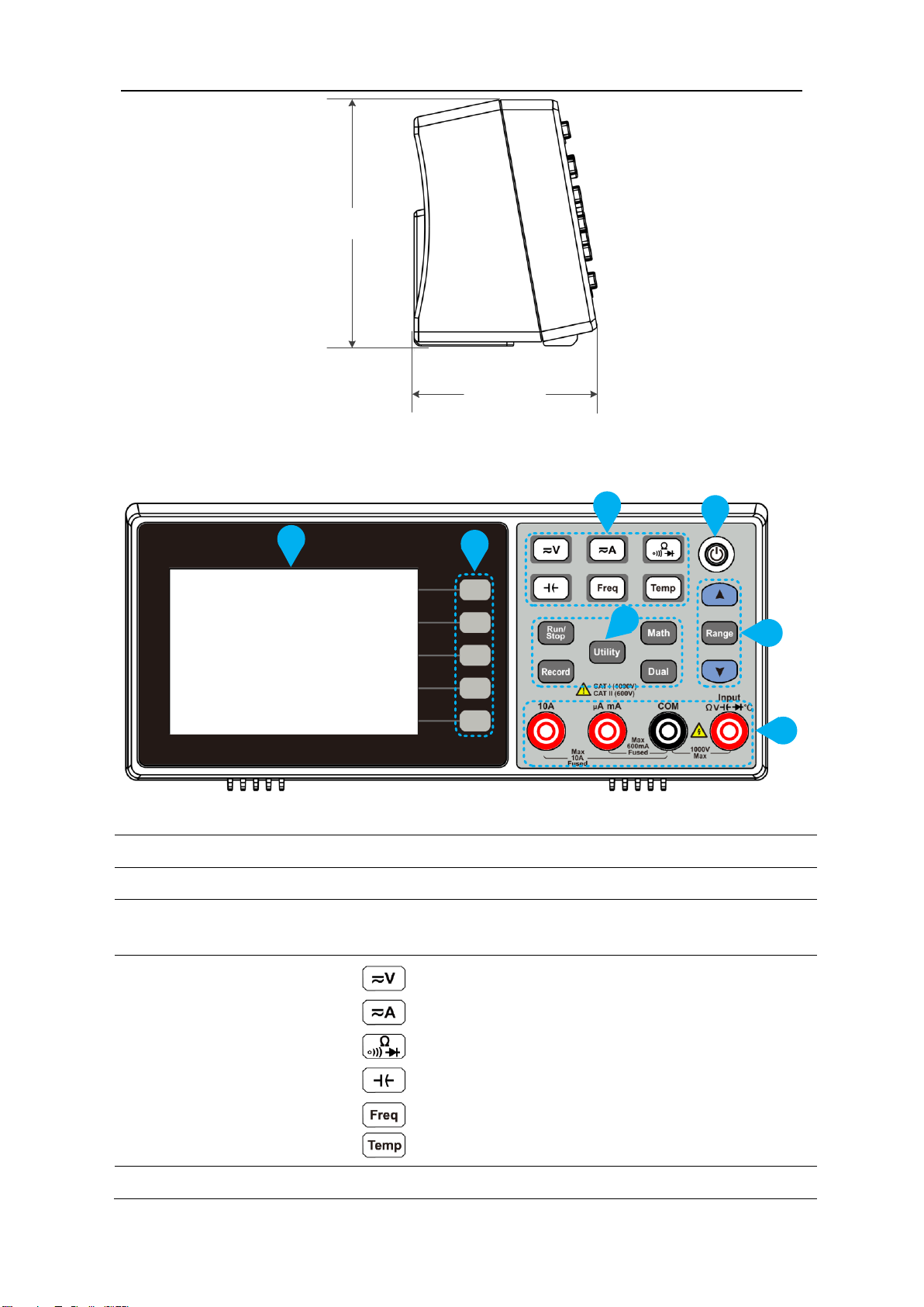
Dimensions......................................................................................................................... 5
Front Panel Overview.......................................................................................................... 6
Rear Panel Overview........................................................................................................... 7
User Interface..................................................................................................................... 8
Power On ........................................................................................................................... 8
Measurement Connections ................................................................................................. 9
3.Functions and Operations .........................................................................................11
To Set the Range................................................................................................................11
Measurement Speed..........................................................................................................12
Basic Measurement Functions............................................................................................12
Measuring DC Voltage ........................................................................................................................12
Measuring AC Voltage ........................................................................................................................13
Measuring DC Current ........................................................................................................................14
Measuring AC Current ........................................................................................................................15
Measuring Resistance.........................................................................................................................16
Continuity Test ...................................................................................................................................17
Diode Test ..........................................................................................................................................18
Measuring Capacitance ......................................................................................................................19
Measuring Frequency and Period .......................................................................................................20
Measuring Temperature.....................................................................................................................21
Dual Display.......................................................................................................................23
Data Hold ..........................................................................................................................24
Math .................................................................................................................................24
Max/Min ............................................................................................................................................24
dB/dBm ..............................................................................................................................................24
Relative Value.....................................................................................................................................25
Data Record Function.........................................................................................................26
Manual Record ...................................................................................................................................26
Auto Record .......................................................................................................................................26
Utility Menu ......................................................................................................................28
Language............................................................................................................................................28
Backlight.............................................................................................................................................28
Clock...................................................................................................................................................28
Default ...............................................................................................................................................28

ii
Serial ......................................................................................................................错误!未定义书签。
4.Measurement Tutorial ..............................................................................................30
Loading Errors (DC Voltage)................................................................................................30
True RMS AC Measurements..............................................................................................31
5.Troubleshooting........................................................................................................32
6.Technical Specifications ............................................................................................33
7.Appendix ..................................................................................................................35
Appendix A: Enclosure .......................................................................................................35
Appendix B: General Care and Cleaning ..............................................................................35
Appendix C: Line Fuse Replacement ...................................................................................35

1.Safety Information
1
1.Safety Information
Safety Terms and Symbols
Safety Terms
Terms in this Manual. The following terms may appear in this manual:
Warning: Warning indicates the conditions or practices that could result in
injury or loss of life.
Caution: Caution indicates the conditions or practices that could result in
damage to this product or other property.
Terms on the Product. The following terms may appear on this product:
Danger: It indicates an injury or hazard may immediately happen.
Warning: It indicates an injury or hazard may be accessible potentially.
Caution: It indicates a potential damage to the instrument or other property might occur.
Safety Symbols
Symbols on the Product. The following symbol may appear on the product:
Direct current (DC)
Warning, risk of electric shock
Alternating current (AC)
Caution, risk of danger (refer to this
manual for specific Warning or
Caution information)
Both direct and
alternating current
Conforms to European Union
directives
Ground terminal
Chassis Ground
IEC Measurement Category I. The maximum measurable voltage
is 1000 Vpk in the HI -LO terminal.
IEC Measurement Category II. Inputs may be connected to AC
mains power (up to 600 VAC) under Category II overvoltage
conditions.
This product complies with the WEEE Directive (2012/19/EC)
marking equipment. The affixed product label indicates that you
must not discard this electrical/electronic product in
domestic household waste.

1.Safety Information
2
General Safety Requirements
Before any operations, please read the following safety precautions to avoid any
possible bodily injury and prevent this product or any other products connected from
damage. In order to avoid any contingent danger, this product is only used within the
range specified.
◼Use Proper Power Cord. Use only the power cord supplied with the product and
certified to use in your country.
◼Product Grounded. This instrument is grounded through the power cord grounding
conductor. To avoid electric shock, the grounding conductor must be grounded. The
product must be grounded properly before any connection with its input or output
terminal.
◼Limit operation to the specified measurement category, voltage, or amperage
ratings.
◼Check all Terminal Ratings. To avoid instrument damage and the risk of electric shock,
check all the Measurement Limits and markers of this product. Refer to the user's
manual for the Measurement Limits before connecting to the instrument. Do not
exceed any of the Measurement Limits defined in the following section.
◼Do not operate without covers. Do not operate the instrument with covers or panels
removed.
◼Use Proper Fuse. Use only the specified type and rating fuse for this instrument.
◼Avoid exposed circuit. Do not touch exposed junctions and components when the
instrument is powered.
◼Do not operate if in any doubt. If you suspect damage occurs to the instrument,
have it inspected by qualified service personnel before further operations.
◼Use your instrument in a well-ventilated area. Inadequate ventilation may cause
increasing of temperature or damages to the device. Please keep well ventilated and
inspect the intake regularly.
◼Do not operate in wet conditions. In order to avoid short circuiting to the interior of
the device or electric shock, please do not operate in a humid environment.
◼Do not operate in an explosive atmosphere.
◼Keep product surfaces clean and dry.
◼Only the qualified technicians can implement the maintenance.

1.Safety Information
3
Measurement Limits
The protection circuitry of the multimeter can prevent damage to the instrument and
protect against the danger of electric shock, when the Measurement Limits are not
exceeded. To ensure safe operation of the instrument, do not exceed the Measurement
Limits shown on the front panel, it is defined as follows:
Main Input Terminals Measurement Limits
The Input and COM Input terminals are used for voltage, resistance,
continuity, frequency (period), capacitance, diode, and temperature test measurements.
The Measurement Limit is defined for these terminals:
Input to COM Input Measurement Limit
The measurement limit from Input to COM Input is 1000 VDC or 750
VAC, which is also the maximum voltage measurement. This limit can also be
expressed as 1000 Vpk maximum.
Current Input Terminal Measurement Limits
The measurement limit from 10A input terminal to COM Input terminal is 10 A (DC or
AC).
The measurement limit from μA mAinput terminal to COM Input terminal is 600 mA
(DC or AC).
Note that the current input terminals will always be at approximately the same voltage as
the COM Input terminal.
Measurement Category
The safety rating of the multimeter:
1000 V, CAT I
IEC Measurement Category I. The maximum measurable voltage is 1000 Vpk in the HI -LO
terminal.
600 V, CAT II
IEC Measurement Category II. Inputs may be connected to AC mains power (up to 600
VAC) under Category II overvoltage conditions.
Measurement category definition
Measurement CAT I applies to measurements performed on circuits not directly
connected to the AC mains. Examples are measurements on circuits not derived from the
AC mains and specially protected (internal) mains- derived circuits.

1.Safety Information
4
Measurement CAT II applies to protect against transients from energy-consuming
equipment supplied from the fixed installation, such as TVs, PCs, portable tools, and
other household circuits.
Measurement CAT III applies to protect against transients in equipment in fixed
equipment installations, such as distribution panels, feeders and short branch circuits,
and lighting systems in large buildings.
Measurement CAT IV applies to measurements performed at the source of the low-
voltage installation. Examples are electricity meters and measurements on primary over
current protection devices and ripple control units.

2.Quick Start
5
2.Quick Start
General Inspection
After you get a new multimeter, it is recommended that you should make a check on the
instrument according to the following steps:
1. Check whether there is any damage caused by transportation.
If it is found that the packaging carton or the foamed plastic protection cushion has
suffered serious damage, do not throw it away first till the complete device and its
accessories succeed in the electrical and mechanical property tests.
2. Check the Accessories
The supplied accessories have been already described in the Appendix A: Enclosure
of this Manual. You can check whether there is any loss of accessories with reference
to this description. If it is found that there is any accessory lost or damaged, please
get in touch with our distributor responsible for this service or our local offices.
3. Check the Complete Instrument
If it is found that there is damage to the appearance of the instrument, or the
instrument cannot work normally, or fails in the performance test, please get in
touch with our distributor responsible for this business or our local offices. If there is
damage to the instrument caused by the transportation, please keep the package.
With the transportation department or our distributor responsible for this business
informed about it, a repairing or replacement of the instrument will be arranged by
us.
Dimensions
200 mm

2.Quick Start
6
86.5 mm
64 mm
Front Panel Overview
2
4
5
1
7
3
6
Figure 2-1 Front panel overview
Item
Name
Description
1
LCD
Display the user interface
2
Menu selection
Keys
Activate the corresponding menu
3
Measurement
Function Keys
DC or AC voltage measurements
DC or AC current measurements
Resistance, continuity, and diode measurements
Capacitance measurements
Frequency/Period measurements
Temperature measurements
4
Power button
Turn on/off the multimeter.

2.Quick Start
7
5
Range/Direction Keys
When the Range softkey is shown on the right menu, you
can press the key to switch between auto and
manual range. Press or keys to enable manual
range, and increase or decrease the measurement range.
When setting a parameter, press to move the
cursor, press or keys to increase or decrease
the value.
6
Operation Keys
Run/Stop
Start or stop auto trigger. When the trigger is stopped, the
displayed data will be held.
Record
Access menus of manual record and auto record.
See page 26, Data Record Function.
Utility
Set the auxiliary system function, including Language,
Backlight, Clock, Default, and Serial port.
Math
Perform math operations (Max/Min, dB/dBm) on the
measurement results.
Dual
Press this key to display the function list on the right menu,
select a function, if the function is supported, the reading
will be displayed in the Vice Display.
7
Input Terminals
Signal input terminals, used for AC/DC current, voltage,
resistance, continuity, frequency (period), capacitance,
diode, and temperature test measurements.
Rear Panel Overview
1
3
2
Figure 2-2 Rear panel overview (Take the -R model for instance )
Item
Name
Description
1
Communication int
erface
-R models can be connected to a computer through a serial port;
-U model can be connected to the computer via USB Device.
2
Line Fuse
The fuse rating is 250 V, F1AL. To replace the fuse, see page
35, Appendix C: Line Fuse Replacement.

2.Quick Start
8
3
AC Mains Input
AC mains input connector.
User Interface
Trigger Mode
Reading
Range Function
Operation Menus
Unit
Status Icon
Figure 2-3 User interface (Single display)
Secondary function
Primary function reading
Primary function
Figure 2-4 User interface (Dual display)
Power On
(1) Connect the instrument to the AC supply using the supplied power cord.
Warning:
To avoid electric shock, the instrument must be grounded properly.
(2) Press down the power button at the front panel, the screen shows the boot screen.
Trigger Mode
Status Icon
Display
Description
Trigger
Auto trigger
Icon
Description
Auto record function is running
Manual record

2.Quick Start
9
Measurement Connections
After selecting the desired measurement function, please connect the signal (device)
under test to the multimeter according to the method below. To avoid instrument
damage, do not discretionarily switch the measurement function when measuring.
DC Voltage Measurement
DC Voltage
AC Voltage Measurement
AC Voltage
DC Current Measurement
DC Current
DC Current
AC Current Measurement
AC Current
AC Current

2.Quick Start
10
Resistance Measurement
Resistance
I
Continuity Test
Open or
Closed Circuit
I
Diode Measurement
I
Forward Bias
Capacitance Measurement
Capacitance
Frequency/Period Measurement
AC Signal
Temperature Measurement
I
Temp
Transducer

3.Functions and Operations
11
3. Functions and Operations
To Set the Range
The instrument provides auto and manual range. In auto range, the multimeter selects a
proper range automatically according to the input signal; in manual range, you can use
the front panel key or menu softkey to set the range. The auto range can bring a lot of
convenience for users while the manual range provides higher reading precision.
1st Method: Use the front panel key to set the range.
When the Range softkey is shown on the right menu, you can press the key to
switch between auto and manual range. Press or keys to enable manual
range, and increase or decrease the measurement range.
2nd Method: Select the range in the measurement function menu.
Select auto range: In the measurement function menu, press the Range softkey, select
Auto.
Select manual range: In the measurement function menu, press the Range softkey, select
a range except Auto.
Note:
⚫When the input signal exceeds the current range, "overload” will be displayed.
⚫By default, the range is set to Auto at power-on or after a reset.
⚫Auto range is recommended if you are not sure about the measurement range in order
to protect the instrument and obtain accurate data.

3.Functions and Operations
12
Measurement Speed
The instrument provides three types of measurement speed:
"Low" speed is 4 reading/s; "Mid" speed is 16 reading/s; "High" speed is 65 reading/s.
In DCV, ACV, DCI, ACI and resistance measurements, the measurement speed is
selectable.
Basic Measurement Functions
Measuring DC Voltage
This section describes how to configure DC voltage measurements.
Operating Steps:
1. Enable the DCV measurement.
Press on the front panel to enter DCV measurement mode.
2. Connect the test lead.
DC Voltage
3. Set the function.
Press the Function softkey to switch between V and mV.
4. Set the range.
Press the Range softkey to set the range. Auto range automatically selects the range
for the measurement based on the input.
Note:
⚫1000 V input protection is available in all ranges.
⚫10% over range for all ranges except 1000 V range.
⚫If the reading exceeds 1050 V in 1000 V range, "overload" will be displayed.

3.Functions and Operations
13
5. Set the measurement speed.
Press the Speed softkey to switch between Low, Mid and High. See page 13 ”
Measurement Speed”.
6. Set the relative value.
Press the Rel softkey to turn on or off the relative operation. For relative operation,
the multimeter subtracts the pre-specified value of REL operation from the actual
measurement result and displays the result. See page 25, Relative Value.
Measuring AC Voltage
This section describes how to configure AC voltage measurements.
Operating Steps:
1. Enable the ACV measurement.
Press on the front panel, press it again to enter ACV measurement mode.
2. Connect the test lead.
AC Voltage
3. Set the function.
Press the Function softkey to switch between V and mV.
4. Set the range.
Press the Range softkey to set the range. Auto range automatically selects the range
for the measurement based on the input.
Note:
⚫750 V input protection is available in all ranges.
⚫10% over range for all ranges except 750 V range.
If the reading exceeds 787.5 V in 750 V range, "overload" will be displayed.
5. Set the measurement speed.
Press the Speed softkey to switch between Low, Mid or High. See page 12,
“Measurement Speed “.

3.Functions and Operations
14
6. Set the relative value.
Press the Rel softkey to turn on or off the relative operation. For relative operation,
the multimeter subtracts the pre-specified value of REL operation from the actual
measurement result and displays the result. See page 25, Relative Value.
Measuring DC Current
This section describes how to configure DC current measurements.
Operating Steps:
1. Enable the DCI measurement.
Press on the front panel to enter DCI measurement mode.
2. Set the function.
Press the Function softkey to switch between A and mA.
3. When the Function is set as A, connect the test lead as below.
DC Current
When the Function is set as mA, connect the test lead as below.
DC Current
4. Set the range.
Press the Range softkey to set the range. Auto range automatically selects the range
for the measurement based on the input.
Note:
⚫The multimeter uses two kinds of fuses for current protection: A 10A fuse is built
into the 10A input terminal for overcurrent protection, and a 600mA fuse is built
into the uAmA input terminal for overcurrent protection.
⚫10% over range for all ranges except 10 A range.
If the reading exceeds 10.5 A in 10 A range, "overload" will be displayed.
5. Set the measurement speed.

3.Functions and Operations
15
Press the Speed softkey to switch between Low, Mid and High. See page 12,
“Measurement Speed “.
6. Set the relative value.
Press the Rel softkey to turn on or off the relative operation. For relative operation,
the multimeter subtracts the pre-specified value of REL operation from the actual
measurement result and displays the result. See page 25, Relative Value.
Measuring AC Current
This section describes how to configure AC current measurements.
Operating Steps:
1. Enable the ACI measurement.
Press on the front panel, press it again to enter ACI measurement mode.
2. Set the function.
Press the Function softkey to switch between A and mA.
3. When the Function is set as A, connect the test lead as below.
AC Current
When the Function is set as mA, connect the test lead as below.

3.Functions and Operations
16
AC Current
4. Set the range.
Press the Range softkey to set the range. Auto range automatically selects the range
for the measurement based on the input.
Note:
⚫The multimeter uses two kinds of fuses for current protection: A 10A fuse is built
into the 10A input terminal for overcurrent protection, and a 600mA fuse is built
into the uAmA input terminal for overcurrent protection.
⚫10% over range for all ranges except 10 A range.
If the reading exceeds 10.5 A in 10 A range, "overload" will be displayed.
5. Set the measurement speed.
Press the Speed softkey to switch between Low, Mid and High. See page 12,
Measurement Speed .
6. Set the relative value.
Press the Rel softkey to turn on or off the relative operation. For relative operation,
the multimeter subtracts the pre-specified value of REL operation from the actual
measurement result and displays the result. See page 25, Relative Value.
Measuring Resistance
This section describes how to configure resistance measurements.
Operating Steps:
1. Enable resistance measurement.
Press on the front panel to enter resistance measurement mode.
2. Connect the test lead.
Other manuals for XDM1000 Series
2
This manual suits for next models
4
Table of contents
Other Owon Multimeter manuals