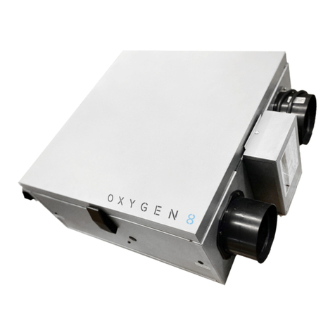
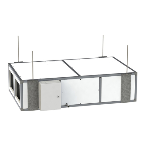
Oxygen 8 NOVA Series Installation guide

OPERATION &
MAINTENANCE
NOVA SERIES

Table of Contents
1.0 General Information 3
2.0 Configuration Chart 4
3.0 Specifications 5
3.1 System Overview 5
3.2 General Specifications 5
3.3 Electrical - ERV/DOAS 6
3.4 Electrical - Fan Coil 7
3.5 Fan and Core Performance 8
ERV 8
HRV 9
Unit Data 9
Air Performance 10
3.6 Dimensions 12
4.0 Configuring Controls 13
4.1 Setting Fan Operating Points 13
4.2 Fan Control: Constant Pressure 15
4.3 Fan Control: Constant Flow 16
4.4 Fan Control: Return Air Pressure 17
Transmitter Adjustment
4.5 Fan Control: Supply Air Pressure 18
Transmitter Adjustment
4.6 Fan Control: Constant CO2 19
4.7 Fan Control: Compensation 20
4.8 Alarm Relay Function 21
4.9 External High 21
4.10 Constant Room 22
4.11 Constant Supply/Return Dierential 22
4.12 Cooling 22
4.13 Summer Night Cooling (Free Cooling) 23
4.14 Humidification 25
4.15 Dehumidification 26
4.16 Summer/Winter Compensation 27
4.17 Summer/Winter Changeover 27
4.18 Locking the Fan Speed 28
4.19 Communication Protocols 29
4.20 Factory Reset 31
5.0 Operation 32
5.1 Speed 32
5.2 Speed Operating Times 33
5.3 Calendar Function 34
5.4 Temperature Setpoint 40
5.5 Time and Date 40
5.6 Alarm and Log 41
5.7 Status Display 42
5.8 Control System Information 42
5.9 Email Settings 43
5.10 Status Display 43
6.0 Maintenance 44
6.1 Fans 44
6.2 DX Coil 45
6.3 Hydronic Coil 45
6.4 Core 46
6.5 Filters 47
6.6 Fuse Replacement 47
6.7 Control Unit 48
Intake Sensor/Discharge Sensor 49
Parameters for Inlet 49
Parameters for Return 50
Parameters for Inlet Fan 51
Parameters for Return/Exhaust Fan 51
Filter Monitoring 52
Pre-heater: Water Battery 54
Pre-heater: Electric Battery 55
Pre-heater: Water Battery 1 56
Pre-heater: Electric Battery 57
Heating: Water Battery 1 58
Heating: Electric Battery 1 59
Heating: Water Battery 2 60
Heating: Electric Battery 2 61
Cooling: Water Cooling 62
Cooling/Heating: Multipurpose Battery 62
Humidifier 64
Heat Recovery: Cross-Flow 65
6.8 Connectors Overview 66
Fire Alarm 67
6.9 Setting Service Functions 68
Alarm and Log 68
7.0 Alarm List 69

Operation and Maintenance Manual Nova Series
3
This manual includes important instructions for safe
installation, operations and maintenance of the Energy
Recovery Ventilator (ERV). Before installing the ERV,
please read carefully and follow all of the instructions
below! The manufacturer reserves the right to make
changes to this manual without prior notification.
Please keep this manual for future reference.
Consider this manual a permanent part of the product.
This manual will show the manufacturers
recommended installation method. Please note
that local codes and regulations may override these
recommendations.
The installation must follow local codes and standards.
The National Electric Code (NEC), the National Fire
Protection Agency (NFPA), and the Canadian Electrical
Code (CEC) must be followed.
Installation of this product must be performed by a
qualified and accredited professional in conformance
with local and national codes, standards and licensing
requirements.
Warnings and Caution
Warnings and cautions appear at the appropriate
sections throughout this manual. Please read these
sections carefully.
Warning
This sign indicates a potentially hazardous situation,
which could result in death or serious injury if not
avoided.
Caution
This sign indicates a potentially hazardous situation,
which may result in minor or moderate injury if not
avoided. It may also alert against unsafe practices.
Caution
This label indicates a situation that may result in
equipment or property damage only accidents.
1.0 General Information

Operation and Maintenance Manual Nova Series
4
The following is a complete description of the packaged ERV/HRV model numbers and nomenclature.
Main Code: NOVA_XXX_XXX_X_X_X_X_XX_X_XX_XX_XX_XX_XXX_XX_XX_X_X_X
NOVA_A16_ERV_B_I_R_H_S1_ND_01_02_3A_04_2401_13_08_2_1_A
Sales Drawings: NOVA_A16_ERV_B_I_R_H_S1_ND_01_02_3A_04_A
Size
A16, A18, B20, C20, C22, C24, C26, C30, C32, C40, C48,
C58, C70
Heat Exchanger
Latent - ERV
Location
Indoor - I
Outdoor - O
Bypass
Bypass - B
Standard - S
Handing
Right Hand - R
Left Hand - L
Installation Orientation
Horizontal - H
Vertical - V
Fan Position
FP1 [Supply Fan - Top] - S1
FP2 [Supply Fan - Bottom] - S2
Condensate Drain Pan in Exhaust Air Path
Not Included - ND
Included - DP - Only available with Bypass & S1
Upper Outlet Air Connection
Straight - 01
Perpendicular - 1A - Not available with outdoor units
Straight-Coupled Coil - 1B - Not available with S2
Lower Outlet Air Connection
Straight - 01
Perpendicular - 1A - Not available with outdoor or vertical
Straight-Coupled Coil - 2B - Not available for outdoor or S1
Downshot - 4D - Not available for indoor units
Power
240/60/1 - 2401
208/60/1 - 2081
208/60/3 - 2083
460/60/3 - 4603
Outdoor Air Filter
MERV8 - 08
MERV11 - 11
MERV13 - 13
MERV14 - 14
Return Air Filter
MERV8 - 08
MERV11 - 11
MERV13 - 13
MERV14 - 14
Mounting Included
None - 0
Hanging Brackets - 1
Base Rails - 2
Controls Included
No - 0
Yes - 1
Version (Generation)
A, B, C....
2.0 Configuration Chart
2A (Optional)
4A (Optional)
1
2
3
4
1A (Optional)
3A (Optional)

Operation and Maintenance Manual Nova Series
5
3.1 System Overview
Standard units come complete with energy recovery option, EC fans, 2" filters, fully integrated controls and casing
as outlined in the spec below.
3.0 Specifications
3.2 General Specifications
Standard Features
Certification
AHRI and UL Certified
Casing
Double-wall 1" insulation for compact indoor models
22 gauge galvanized steel inner panel with 20 gauge
pre-painted white outer panel
Electrical and Controls
Configurable integrated controller with BACNet
compatibility
Single point power
Filters
2" pleated OA MERV 13, RA MERV 8
Blowers and Motors
High-eciency variable speed EC direct-drive motor
Backward inclined fan
Warranty
Core - 5 years from shipping
Unit - 2 years from shipping
Mounting
Ceiling, wall*, or floor-mount
*Hardware and Engineering by Others
Options
Integrated Heating and Cooling
Hydronic, Electric, DX Coils (using EEV kit) and
pre-heat available
Bypass Damper
Bypass economizer, bypass defrost
Shut O Damper
Outdoor and exhaust air dampers (unit or duct
mounted)
Frost Control
Electric Preheat
Warranty

Operation and Maintenance Manual Nova Series
6
3.3 Electrical ―DOAS/ERV
Model Nom. V. Motor
kW
SA Fan FLA SA Fan FLA Tnsfmr FLA MCA MROP D Rcmd Fuse
A16/A18 240 0.5 2.50 2.50 0.29 5.91 8.41 15A
B20/B22 240 0.78 3.90 3.90 0.29 9.06 12.96 15A
B20/B22 208 2.00 6.00 6.00 0.33 13.83 19.83 15A
B20/B22 460 2.50 4.00 4.00 0.14 9.14 13.14 15A
C20/C22 208 2.00 6.00 6.00 0.33 13.83 19.83 15A
C20/C22 460 2.50 4.00 4.00 0.14 9.14 13.14 15A
C24/C26 208 2.7 8.60 8.60 0.33 19.68 28.28 25A
C24/C26 460 3.7 5.80 5.80 0.14 13.19 18.99 15A
C30/C32 208 3 9.00 9.00 0.33 20.58 29.58 25A
C30/C32 460 3.3 5.40 5.40 0.14 12.29 17.69 15A
C40 208 2.00 6.00 6.00 0.33 27.33 39.33 35A
C40 460 2.50 4.00 4.00 0.14 18.14 26.14 25A
C48 208 2.7 8.60 8.60 0.33 39.03 56.23 50A
C48 460 3.7 5.80 5.80 0.14 26.24 37.84 35A
C58 208 2.00 6.00 6.00 0.33 40.83 58.83 50A
C58 460 2.50 4.00 4.00 0.14 27.14 39.14 35A
C70 208 2.7 8.60 8.60 0.33 58.38 84.18 80A
C70 460 3.7 5.80 5.80 0.14 39.29 56.69 50A

Operation and Maintenance Manual Nova Series
3.4 Fan and Core Performance
ERV Performance
Model Airflow (cfm) SRE LRE TRE PD (Supply, Return)
1" Insulation / Indoor Units
A16 400
775
69%
61%
54%
43%
60%
50%
0.36, 0.72
0.62, 1.26
B20 700
1300
68%
60%
55%
44%
60%
50%
0.33, 0.55
0.6, 1.05
C20 700
1300
68%
60%
55%
44%
60%
50%
0.33, 0.55
0.6, 1.05
C24 1550
2700
68%
60%
55%
44%
60%
50%
0.45, 0.79
0.86, 1.64
C30 2000
3500
68%
60%
55%
44%
60%
50%
0.45, 0.79
0.87, 1.66
2" Insulation / Outdoor Units
A18 400
775
69%
61%
54%
43%
60%
50%
0.36, 0.72
0.62, 1.26
B22 700
1300
68%
60%
55%
44%
60%
50%
0.33, 0.55
0.6, 1.05
C22 1225
2200
68%
60%
55%
44%
60%
50%
0.44, 0.78
0.88, 1.68
C26 1550
2700
68%
60%
55%
44%
60%
50%
0.45, 0.79
0.86, 1.64
C32 2000
3500
68%
60%
55%
44%
60%
50%
0.45, 0.79
0.87, 1.66
C40 2450
4400
68%
60%
55%
44%
60%
50%
0.44, 0.78
0.88, 1.68
C48 3100
5400
68%
60%
55%
44%
60%
50%
0.45, 0.79
0.86, 1.64
C58 3675
6600
68%
60%
55%
44%
60%
50%
0.44, 0.78
0.88, 1.68
C70 4650
8100
68%
60%
55%
44%
60%
50%
0.45, 0.79
0.86, 1.64

Operation and Maintenance Manual Nova Series
8
Fan Data
Model CFM Nominal Voltage / FLA (A) FLA (A) KW SP "Wg
A16/A18 775 240/1/60 / 1.8 2.5 0.5 3
B20/B22 1300 2401/60 / 2.8 3.9 0.78 3.1
B20/B22 1300 208/3/60 / 2.8 6.0 2.0 5.9
B20/B22 1300 460/3/60 / 2.8 4.0 2.5 7.0
C20/C22 2200 208/3/60 / 5.0 6.0 2.0 5.9
C20/C22 2200 460/3/60 / 3.2 4.0 2.5 7.0
C24/C26 2700 208/3/60 / 7.2 8.6 2.7 5.4
C24/C26 2200 460/3/60 / 4.6 5.8 3.7 7.0
C30/C32 3500 208/3/60 / 7.6 9.0 3.0 4.6
C30/C32 3500 460/3/60 / 4.2 5.4 3.3 5.1
C40 4400 208/3/60 / 6.4 6.0 2.0 7.0
C40 4400 460/3/60 / 6.4 4.0 2.5 5.0
C48 5400 208/3/60 / 9.2 8.6 2.7 7.0
C48 5400 460/3/60 / 9.2 5.8 3.7 5.0
C58 6600 208/3/60 / 9.6 6.0 2.0 5.1
C58 6600 460/3/60 / 9.6 4.0 2.5 5.0
C70 8100 208/3/60 / 13.8 8.6 2.7 5.0
C70 8100 460/3/60 / 13.8 5.8 3.7 5.0

Operation and Maintenance Manual Nova Series
9
Air Performance
A16 ―775 cfm ―240/1 B20 ―775 cfm ―240/1
B20 ―1300 cfm ―460/3
C20 ―1600 cfm ―460/3
C20 ―1600 cfm ―208/3
B20 ―1300 cfm ―208/3

Operation and Maintenance Manual Nova Series
10
Air Performance
C24 ―2700 cfm ―460/3
C30 ―3500 cfm ―460/3
C40 ―4400 cfm ―460/3
C40 ―4400 cfm ―208/3
C30 ―3500 cfm ―208/3
C24 ―2700 cfm ―208/3

Operation and Maintenance Manual Nova Series
11
Air Performance
C48 ―5400 cfm ―460/3
C58 ―6600 cfm ―460/3
C70 ―8800 cfm ―460/3
C70 ―8100 cfm ―208/3
C58 ―6600 cfm ―208/3
C48 ―5400 cfm ―208/3

Operation and Maintenance Manual Nova Series
12
3.5 Dimensions
A16
A18

Operation and Maintenance Manual Nova Series
13
B20
B22

Operation and Maintenance Manual Nova Series
14
C20
C22

Operation and Maintenance Manual Nova Series
15
C24
C26

Operation and Maintenance Manual Nova Series
16
C30
C32

Operation and Maintenance Manual Nova Series
17
C40
C48

Operation and Maintenance Manual Nova Series
18
C58
C70

Operation and Maintenance Manual Nova Series
19
4.1 Setting the Fan Operating Points
Setting Control Functions
Under the “Installer->Operating->Setpoint” tab, you can set the way in which fans and air volumes are to be
controlled and regulated.
Fans and air volumes can be controlled according to the following operating modes: see next pages.
General Information About the
Start-Up Sequence
1. When the system is activated, the following
start-up sequence is followed regardless of
the selected control type (constant pressure,
constant flow, CO2, exhaust slave, etc.):
2. The exhaust fan is started.
3. Heat recovery is overridden to 100% (rotary,
cross-flow, counter-flow or fluid coupled heat
exchanger).
4. The heating valve is overridden to the value
(Startup heating) set under “Factory/Settings/
Components” – only applies in the case of a
water-based heating battery.
5. Exhaust fan speed is increased until it reaches
the setpoint for air quantity/duct pressure.
6. When the exhaust fan has reached its setpoint,
the Supply fan is started.
7. Supply fan speed is increased until it reaches
50% of the setpoint for air quantity/duct pressure.
8. When the Supply fan has passed 50% of
the setpoint for air quantity/duct pressure,
the override signals for heat recovery and
heating valve (see items 1.1 and 1.2 above) are
discontinued.
4.0 Configuring Controls

Operation and Maintenance Manual Nova Series
20
Constant Pressure
• Supply and return fans are controlled in relation
to the pressure in the Supply and return ducts
respectively.
• The system must be equipped with two separate
pressure transmitters, one in the Supply duct and
the other in the return duct.
• Pressure transmitters of PTH type are suitable.
• Pressure transmitters used to measure pressure
dierences across the fans cannot be omitted as
these are used to regulate the air flow.
Constant Flow
• Supply and return fans are controlled in relation
to flow/air volumes in the Supply and return
ducts respectively.
• Air volumes are measured/calculated by
measuring the dierence between static and
dynamic pressure across the fan.
• The dierence between static and dynamic
pressure is measured by means of pressure
transmitters, either the pressure transmitters built
into the OJ-Air2 FanIO or pressure transmitters of
PTH type.
Return Slave
• The Supply fan is controlled in relation to the
pressure in the Supply duct while the return fan
is controlled as a slave of the Supply fan with a
freely selected oset.
• The system need only be equipped with pressure
transmitters in the Supply duct.
• Pressure transmitters of PTH type are suitable.
• Pressure transmitters used to measure pressure
dierences across the fans cannot be omitted as
these are used to control the air flow.
Supply Slave
• The return fan is controlled in relation to the
pressure in the return duct while the supply fan
is controlled as a slave of the return fan with a
freely selected oset.
• The system need only be equipped with pressure
transmitters in the return duct.
• Pressure transmitters of PTH type are suitable.
• Pressure transmitters used to measure pressure
dierences across the fans cannot be omitted as
these are used to control the air flow.
Constant VOC/CO2
• The system must be configured with a CO2
sensor.
• The CO2 sensor can either be positioned in the
room as a room sensor or in the return duct as a
duct sensor.
• Irrespective of whether the CO2 sensor
is a room or duct sensor, the CO2
sensor must be configured under “OJ
Modules>Configure>Analogue I/O”.
VOC/CO2 Control
• If the system is not configured for “Recirculation”,
the CO2 concentration in the room is controlled
by regulating air volume via fan speed.
• If the CO2 level in the room rises, fan speed is
increased, thus increasing air volume/air turnover
towards the max. air volume setting.
• If the CO2 level in the room falls, fan speed is
decreased, thus reducing air volume/air turnover
towards the min. air volume setting.
Constant Motor Speed
• Supply air and return air fans will be controlled
on a fixed speed according to the setpoints here
– low (medium if selected) high speed.
• Setpoints can be set individually for supply air
and return/exhaust on low (medium if selected)
high speed.
• If medium speed is not available: Check if
medium speed is configured under: OJ Modules
> Configure > Settings)
Other manuals for NOVA Series
2
Table of contents
Other Oxygen 8 Fan manuals
Popular Fan manuals by other brands

Yamagata
Yamagata YFT2012M instruction manual

Taurus Alpatec
Taurus Alpatec Babel manual

Monte Carlo Fan Company
Monte Carlo Fan Company 5AB52XX Series Owner's guide and installation manual

EIPL
EIPL 10289MG-GB user manual

Monte Carlo Fan Company
Monte Carlo Fan Company 3SU54BK Owner's guide and installation manual

HPM
HPM EF100SQWE instruction manual

Goobay
Goobay 62061 user manual

Genvex
Genvex ECO 375 installation manual

Ellington
Ellington E-VER54ABZ5LKRW installation guide

Modern Forms
Modern Forms ELF installation instructions

Home Decorators Collection
Home Decorators Collection KENSGROVE YG493ODC-MBK Use and care guide

EDM
EDM 33945 instruction manual