Oxylitre AP4600 MK3 Series User manual

Automatic Twin Cylinder Changeover System (AP4600 Series MK3)
Instruction for Use
Made In the UK
2797
Oxylitre Holdings Limited

1
CONTENTS
1
Cautions
2
Introduction
3
Guide to the Oxylitre Twin Cylinder Changeover System User
Interface
4
User Interface
4.1
System Pressure (Seven Segment) Display
4.2
Cylinder Status Indicators
4.3
System Over-Pressure Indicators
4.4
Cylinder Selection Supply Indicators
4.5
TEST Button
4.6
ALARM MUTE Button
4.7
PRESS (to select a cylinder) Button
5
Operating the Unit
5.1
Electrical Connection
5.2
Start-up Instruction after Power Down
5.3
Safety Precautions for the Prevention of Fire & Explosion
5.4
Cylinder Connection
5.5
Audible Alarm Function and Visual References
5.6
Automatic Changeover
5.7
Over Pressure Safety Features
6
Servicing, Preventative Maintenance & Cleaning
6.1
Pipeline Inspection
6.2
Cleaning
6.3
Service/Repair
7
EQUIPMENT application specification
8
Technical Data
9
Materials Specification
10
Disposal
11
Symbol Definition
12
Contact Details

2
1. Cautions
Please read these Operating Instructions carefully. This device is only to be used by fully trained
personnel. Ensure that the device is tested for electrical safety at least annually. The pipeline system
should be subjected to preventative maintenance to ensure the systems’reliability.
To operate the Automatic Twin Cylinder Changeover System correctly, ensure that the Operating
Instructions in this document are followed. Ensure the cleaning procedure and safety precautions are
followed to avoid the risk of fire and explosion. Contact our Service Department immediately if an
electrical fault has been detected when using the Automatic Twin Cylinder Changeover System.
Inspect the condition of the pipeline for any sign of damage i.e. probes, tubing, outlets crimp connections
etc.
Ensure that you check the contents of your package thoroughly before use.
Ensure the cable is neatly wrapped prior to moving.
Please avoid using the unit near other types of electrical equipment that are non-approved electrical
medical devices that may release strong electromagnetic/radiated emissions.
DO NOT stretch, pull or force the connecting hose through an acute bend.
DO NOT use any flammable agents near or on the equipment when in use.
DO NOT subject the system to excessive amounts of water or cleaning fluid or allow surfaces to become
excessively wet.
DO NOT jet wash the product or use in severe / wet environments.
DO NOT clean the system whilst pressurised.
DO NOT stretch or pull the 12 volt DC cable and avoid contact with any sharp implements that may
penetrate the cable.
DO NOT remove the front panel of the Automatic Twin Cylinder Changeover System for any reason. If
the unit fails to operateyou MUSTcontact the Oxylitre Service Department for service recommendations.
The panels on the product must only be opened by an Oxylitre Service Engineer or by qualified
personnel.
2. Introduction
The unit has been specifically designed for use with a twin supply pipeline system. The Automatic
Changeover System is available for both Oxygen, ENTONOX and Medical Air 4 Bar.
This system manages the Change-over process from one cylinder to another automatically, switching
over to the other cylinder when the cylinder pressure is low.
The Automatic Changeover Systems robust design features a flame retardant case, with green flow
direction indication LED’s, red empty cylinder LED’s, a buzzer/alarm to indicate that the system has
switched cylinders or no gas is available. The system is also Ambulance Control Module compatible.

3
(Note: It has been tested to withstand an acceleration/deceleration of 20g, twice the Ambulance
Standard requirement).
The unit is intended to be wall mounted and connects to a 12V - 17V DC power supply from an
Ambulance/Road Vehicle or an Air Ambulance. The unit is classified as a Class II, Type BF Electrical
Medical Device.
Please note this device is not MR conditional.
Intended Use
To aid in the supply of medical gas in ambulance vehicles as defined in BS EN 1789:2007+ A2:2014,
BS 5682: 2015 and HTM2022 Supplement 2.
2.1 Pre-Use Inspection
Remove all packaging from your Automatic Changeover System, inspect all parts for any signs of
damage and ensure all of the contents are there. If you see any signs or suspect that the unit may have
been damaged, DO NOT use. Notify Oxylitre immediately.
2.2 Contraindications
None known
2.3 Warranty
The Company Warranty; in respect of durable goods (but not in respect of disposable goods) that such
goods will correspond with their specification at the time of delivery and will be free from defects in
material and workmanship for a period of 7 years from delivery (N.B. Warranty is 1 year for the battery
and 3 years for the Oxylitre Jar).
Our full warranty statement is available on request.

4
3. Guide to the Oxylitre Twin Cylinder Changeover System
User Interface
Cylinder Selection Supply Graph
Test Button
Primary Supply
Press to Select Cylinder
Cylinder Status LED
Alarm Mute
Secondary Supply
Outer Case
System line Pressure
Indicator

5
4 User Interface
4.1 System Pressure (Seven Segment) Display
Once the unit has been connected / wired into the ambulance 12v DC system, the Seven Segment
Display will indicate the System Pressure and the fact that the unit is on by illuminating. If this display
fails to illuminate, contact Oxylitre Service Department.
4.2 Cylinder Status Indicators
The interface has two Cylinder Status Indicators, one on each of the graphical cylinders. The Cylinder
Status Indicators are tri-colour LEDs. The Indicators will illuminate red when the unit is first connected
to a power supply and will remain illuminated red unit a gas supply has been detected from a particular
cylinder. The Cylinder Status Indicators colour sequences are as follows:
RED The cylinder detects no supply pressure from cylinder.
GREEN The system detects supply pressure above 3.1 bar (45 psi) from the cylinder.
AMBER The system is in test mode.
4.3 System Over-Pressure Indicators
If the active cylinder over-pressurises the System Pressure Display will display pressure until it registers
5.9 bar then it will then flash ‘HI’ on the display. A repeating alarm will sound and the cylinder status LED
will flash Red. The unit will the automatically switch to the other cylinder, the alarm will stop but the
cylinder status LED for the over-pressure cylinder will continue to flash Red. If the other cylinder is also
over-pressure i.e. reaches circa 6 bar (87 psi), the high pressure relief valve will vent.
4.4 Cylinder Selection Supply Indicators
This green LED bar graph indicates which cylinder has been selected. Either the left hand or the right
hand side will illuminate at any given time.
4.5 Test Button
This button allows you to run a user initiated illumination test. This short
program is designed to identify whether the units’audible and electronic visual
aides are operating satisfactorily. To start the test program simply press the
Test Button. This test can be performed at any time and will not interfere with
the gas supply.
TEST

6
Test Sequence
Stage 1
Alarm sounds / System Pressure
(Seven Segment) Display
Alarm bleeps for a few seconds. The
Display flashes ‘8.8’ and continues
throughout each Stage
Stage 2
Cylinder Selection Indicator
Left hand side illuminated for a few
seconds
Stage 3
Cylinder Selection Indicator
Right hand side illuminated for a few
seconds
Stage 4
Cylinder Status Indicator
Left hand side LED illuminated amber
for a few seconds
Stage 5
Cylinder Status Indicator
Right hand side LED illuminated
amber for a few seconds
Stage 6
Alarm sounds / Cylinder
Selection Indicator & Cylinder
Status Indicator
Alarm bleeps for a few seconds. Both
Left & Right Selection Indicators
illuminate and both Left & Right LEDs
illuminate amber for a few seconds
If any of the stages are not performed contact Oxylitre Service Department. Once the test program has
been run the unit will return to normal function.
4.6 Alarm Mute Button
This is a multifunctional button; this button allows the user to silence the alarm.
This is useful when removing cylinders, carrying out maintenance, or purging the
system. Pressing the Alarm Mute Button or the Test Button will automatically bring
the audible alarm back online.
After maintenance work, replacing an empty cylinder or when the system is fully
operational, this button is also used to allow the unit to reset the system. The unit
will perform an input pressure availability inspection, to determine the input
pressure. Once the unit has performed this inspection, the unit will default to the left hand (primary)
cylinder if input pressure is available from the default side.
4.7 Press (to select either cylinder) Button
This button allows the user to select the cylinder they would like to operate the
pipeline system from, and which touse as the reserve. This allows the userto have
greater flexibility over their gas usage if the cylinder selected is emptied or
disconnected causing the system to automatically changeover. The button on the
now failed input side is locked out until the supply has been re-established and the
unit has been reset by pressing the ALARM MUTE button.
!
Press

7
5 Operating the Unit
5.1 Electrical Connection
Connect the Automatic Twin Cylinder Changeover System to the Ambulance 12v DC supply according
to the ambulance fitter guidelines.
DO NOT pressurise the pipeline system until the system has been wired into the Ambulance system.
Upon connection to a 12v DC supply the audible alarm will sound continuously, two red horizontal lines
will light up in themiddle of the Seven Segment Display and the Cylinder Status Indicators will illuminate
red. This is because the pipeline system has not yet been pressurized.
You can silence the alarm by pressing the Alarm Mute button. The unit is now ready to connect to the
cylinders.
5.2 Start-Up Instruction after Power Down
The unit has a built in left hand side bias, called the primary cylinder side. This gives the end user the
option of running the ambulance piped gas system with a dedicated reserve cylinder, only having to
replace one cylinder, the primary cylinder on a regular basis.
Step 1 Connect the hose tail on the primary cylinder side to the primary cylinder. Do not turn on the
cylinder.
Step 2 Connect the hose tail on the reserve /secondary cylinder side to the reserve cylinder. Do not
turn on cylinder.
Step 3 Turn on the primary side cylinder and pressurise the system. The system will perform an input
availability inspection test as mentioned in paragraph 3.6 then automatically select the primary
side. The alarm will then sound for a few seconds to alert you to the fact that the secondary /
reserve side has no supply pressure.
Step 4 Turn on the secondary / reserve cylinder to pressurise secondary side of the unit. Press the
Alarm Mute button the unit will then perform the input availability test. This will bring the
secondary / reserve cylinder online and enable full use of the Automatic Twin Cylinder
Changeover System. The unit is now fully operational.
N.B If the unit alarm fails to silence and / or the secondary cylinder side fails to come online after the
input availability test, press the Test button to reset system.
5.3 Safety Precautions for the Prevention of Fire & Explosion

8
When this product is used with an oxygensupply, ensure the area is well ventilated to prevent high levels
of oxygen accumulating. The regulator or patient MUST NOT be allowed near any source of ignition i.e.:
a). Cigarette/Cigar Smokers. b). Sparks
c). Naked Flames. d). Open electrical appliances
These precautions must also be observed during and after patient use.
Warning: This device MUST NOT come into contact with any oil or grease; a reaction may cause an
explosion / fire.
5.4 Cylinder Connection
The Automatic Twin Cylinder Changeover System has been designed to operate from two gas supply
cylinders each having a regulator fitted and connected to the pipeline system. Only one cylinder can be
operational at any one time. When one cylinder becomes empty, the Automatic Twin Cylinder Change-
Over System will switch to the full cylinder so that the empty cylinder can be disconnected and replaced.
The cylinder status indicator LEDs will indicate when the cylinder is ready for use (this is indicated when
LED turns green) and System Line Pressure (Seven Segment) Indicator will display the cylinder
pressure.
5.5 Audible Alarm Function & Visual References
The audible alarm is a constant 75 dB tone which will sound for a five seconds to inform the user that
the system has performed an automatic changeover has taken place. In the event of this happening the
Cylinder Status Indicator will be illuminate red and the Press (to select a cylinder) Button will be locked
out on the failed cylinder side.
To bring the failed side back on line change the cylinder and reset the unit reference 4.6.
5.6 Automatic Input pressure inspection
If the vehicle/system is to be left unattended overnight, it is advised to turn off the cylinders, drain the
system, and mute the alarm and power down the unit. The system has been designed to perform a gas
availability test on both the reserve cylinder and primary cylinders to ensure that there is a readily
available supply of gas. The system does this by venting gas for four seconds to try to establish the
condition of the primary and reserve/secondary supplies. If the system fails to detect a constant primary
or secondary supply of gas the unit will ALARM for five seconds and the Cylinder Status Indicator will
be illuminate red. The primary or reserve/secondary supply will be locked out, to reset system see 5.7,
if there is not any input gas available and the ALARM will sound constantly for sixty seconds. Note the
alarm can be over ridden with operation reference 3.6. The above inspection has been designed to be
performed after 10 hours if the unit has been stood idle.
5.6 Automatic Changeover
The unit is designed to automatically switch from an active input supply from either cylinder once that
input supply pressure has dropped to less than 3.1 bar. The Twin Cylinder Automatic Changeover upon

9
initial installation or after installing a replacement cylinder will automatically default to the left hand
cylinder. If this is not available the unit will automatically changeover to the right hand cylinder.
5.7 Over pressure Safety features
The Automatic Changeover System has some key features to warn of a build-up of pressure from an
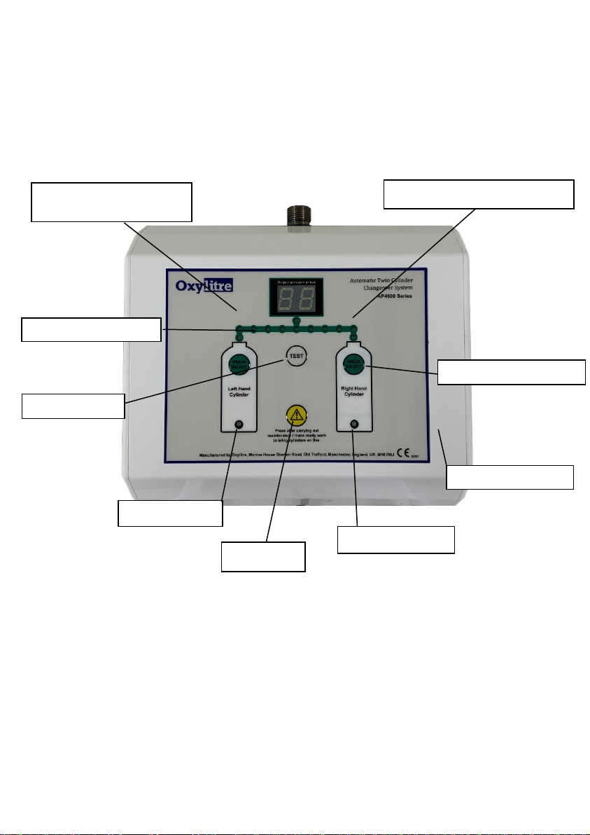
active cylinder. The Automatic Changeover System’s Line Pressure Display will flash ‘HI’ when a
pressure in excess of a nominal 5.6 bar has been achieved. Once a pressure of in excess of 6.0 bar has
been achieved in the pipeline system, the Automatic Changeover System will automatically switch to the
other bottle and give an audible alarm of 75 dB ‘triple bleeps’, lasting for five seconds. The Cylinder
Status Indicator will flash red, denoting a cylinder with unsafe high working pressure.
The unsafe, high pressure cylinder will remain locked out until it is replaced. To bring the failed side back
on line change the cylinder and reset the unit reference 4.6.
6 Servicing, Maintenance and Cleaning
Intended to be serviced annually, see maintenance & service manual. An Ambulance Pipeline System
forms part of an essential support system. The whole system must be treated with care and serviced on
a regular basis, (i.e. preventative maintenance) to ensure the systems quality and reliability.
6.1 Pipeline Inspection (once per annum minimum)
Inspect the condition of the Pipeline for any damage i.e. damage to the probe, tubing, ferrules, outlets
etc. Also carry out routine testing and general safety protocols in accordance with HTM2022.
6.2 Cleaning (to be carried out on a regular basis)
The Pipeline system and Automatic Twin Cylinder Changeover unit requires cleaning on external
surfaces only. PVC compatible cleaning fluid may be used for the cleaning of hose tails. Abrasive
cleaning agents should not be used. Avoid cleaning fluid from entering into any pipeline orifices i.e.
probes, outlets etc.
Avoid cleaning fluid from entering into any Pipeline orifices i.e. probes, outlets etc.
If cleaning fluid is used, apply cleaning fluid to a cloth/other. Dry immediately with a dry cloth/other after
application.
DO NOT use any oil based cleaning fluids (note: some soaps are oil based).
DO NOT rinse or use excessive amounts of water or fluid over the Automatic Changeover System.
DO NOT submerse this unit in water.
6.3 Service / Repair
Servicing should only be carried out by fully qualified technicians / engineers. Details of components
parts etc will be supplied during any required technical training at Oxylitre. For service enquiries and
information, please contact our service department (service@oxylitre.co.uk).
Do not open the enclosure. Unauthorised repairs will invalidate the warranty.
NEVER USE FAULTY EQUIPMENT. Preventative maintenance ensures safety for the patient and user.
There are no contraindications in use.

10
Each unit comes complete with a Manufacturers’ 5-year Warranty (with possible extension).
7 EQUIPMENT application specification
The Automatic Changeover has been designed to meet the essential requirements of IEC 60601-1-2.
Medical purpose
To deliver medical gas from a maximum of twocompressedmedical gas cylinders via a piped gas system
in medical vehicles and road ambulances.
Intended Operator
The unit is to be used by trained medical or paramedical staff who understands the use medical piped
gas systems and the required working pressures of medical vehicles and their equipment.
Intended User Profile
Age: Adult
Nationality: Multiple
Gender: Male or Female
Cultural: Multiple
Condition: Mentally Stable
Level of Competence:
Minimum-Medically Competent,
No maximum
Patient Population
Age: new born to adult
Nationality: Multiple
Weight: >2.5 Kg
Application Environment
Ambulance/ road vehicle
Hospital
Not suitable for use in the presence of flammable liquids or gases.
Not intended for outdoor use, can withstand spraying of water (IP53D)
Protected against spraying water from at up to 60 degrees from vertical.
Protected against the access with a wire.
Intended to be serviced annually
Meets requirements of IEC 60601-1 for environmental tests
Conditions of visibility of Markings
LED display is visible from 1+ metre
Ambient luminance 100 –500 lux (normal conditions)
Control buttons are phosphorescently marked and can be distinguished in the dark
Applied Part Interaction
There is no direct contact with the patient.
Application
Working pressure up to 4bar to 6bar (60 to 90 psi) nominal

11
Weight 1.5 kg
Wall Mounted
Flame retardant enclosure.
Frequency of Use: Continuous operation
8 Technical Data
Warning the modification of the equipment or the removal of any parts is strictly
prohibited and will rescind your warranty. Such action may lead to the unit failing in
service.
Certification compliance
VCA/BS EN 1789; IEC 60601-1; IEC 60601-1-2 (also complies with relevant sections
of ISO 7396-1)
Not suitable for use in the presence of flammable liquids or gases.
Protection
IP53D according to BS EN 60529: 1992
Dust Protected
Protected against spraying water from at up to 60 degrees from vertical.
Protected against the access with a wire.
Performance:
Units of Measurement: Bar
Pressure Range: 3.0 to 6.0
Accuracy: ±5% on indicated value
Flowrate: 40lpm minimum delivery
Permitted Leakage: Zero
Unit Dimensions
Height: 210mm
Width: 145mm
Depth: 73mm
Weight: 1.5 Kg (excluding Hose Tails)
Electronics
Mains Input Voltage: 12-17 VDC nominal
0.5m 2 core black cable
Operation: Constant operation
Method of Isolation: Unplug supply cable from the control PCB
Input Protection: 3.7 amp resettable thermal fuse
Components: RoHS compatible
Control Voltage: 12 VDC
Management: ICU/Software managed
Power Consumption: 1 amp maximum at 12 VDC
Classification: ll
Level of Protection: Type B
03 7549

12
Alarm Noise Level: 75 dB
Electrical/Electronic Test
Electrical/Electronic Safety: BS EN 60601-1
EMC emissions: BS EN 60601-1-2
Medical Gas Input
Working pressure: 3.1 –5.7 bar
System Output pressure: 4 bar nominal (cylinder regulator output dependant)
Environmental Conditions for use Transport and Storage
Operating Temperature: 0 to 40 °C
Storage Temperature: 0 to 40°C
Humidity (Operating & Storage): 5-95% RH non-condensing
Atmospheric pressure range: 50kPa to 106kPa
9
Materials Specification
Enclosure (Front)
Fire Retardant ABS
Rear Mounting Panel
6026 T9 Aluminium
BS5682 Probe
303 Stainless Steel
ACU Keypad Membrane
Polyester
PCB Mounting Bracket
Aluminium
PCB Mounts Female/Female
Delrin
Main Manifold Assembly Block
Brass/ Steel/ Nitrile
Micro Valve Manifolds
Aluminium
Screws
Steel
Hose
PVC
10 Disposal:
Not for general waste. At the end of life cycle, the
Automatic Changeover System is to be disposed of in
accordance with the European Directive on the safe
disposal of Electrical / Electronic Products and as
such shall be handed over to the applicable collection
centre for the recycling of electrical / electronic
equipment.

13
All items to be disposed of should first be
decontaminated to reduce the risk of contamination.
Alternatively contact Oxylitre for details of disposal
procedure / collection.
14
Symbol Definition
Direct current (DC)
Class II equipment
Type BF applied part
Rating of the degree of protection against intrusive implements and
the protection of the environment.
The product has been designed tocomply with the safety and design
requirements of the European Directives for Medical Devices
including Council Directive 93/42/EEC
The product complies with the requirements of the relevant Safety
European Automotive Directives for use in Ambulances and other
Medical Vehicles.
Follow instructions for use.
Indicates: “Caution”
Waste Electrical & Electronic Equipment (WEEE) compliance
(Environmental Agency Producer Registration Number:
WEE/AJ0509VR).
Please contact Oxylitre for details of obligated waste collection.
Pthalate-Free Hose.
Table of contents
Other Oxylitre Medical Equipment manuals
Popular Medical Equipment manuals by other brands

AtriCure
AtriCure cryoICE BOX Quick reference guide

ZOLL
ZOLL aed pro Information booklet

Hill Laboratories
Hill Laboratories HF54 Plus Instructions for use

Zimmer
Zimmer Z Wave Med Instructions for use

Ivy Biomedical Systems
Ivy Biomedical Systems 580076 Regulatory information

Morita
Morita Root ZX mini operating instructions