SCHWIND ESIRIS User manual

EXCIMERLASER
ESIRIS
SERVICE MANUAL
Schwind GmbH
Mainparkstrasse 6-10
D-63801 Kleinostheim

S
SE
ER
RV
VI
IC
CE
E
M
MA
AN
NU
UA
AL
L
2 of
79
___________________________________________________________________________
_______
ESIRIS -- Version 1.0 Date: 22.09.00

S
SE
ER
RV
VI
IC
CE
E
M
MA
AN
NU
UA
AL
L
3 of
79
___________________________________________________________________________
_______
ESIRIS -- Version 1.0 Date: 22.09.00
INDEX PAGE
1. SECURITY OF DEVICE (LASER BEAM) ...........................................................................................5
GENERAL...................................................................................................................................................5
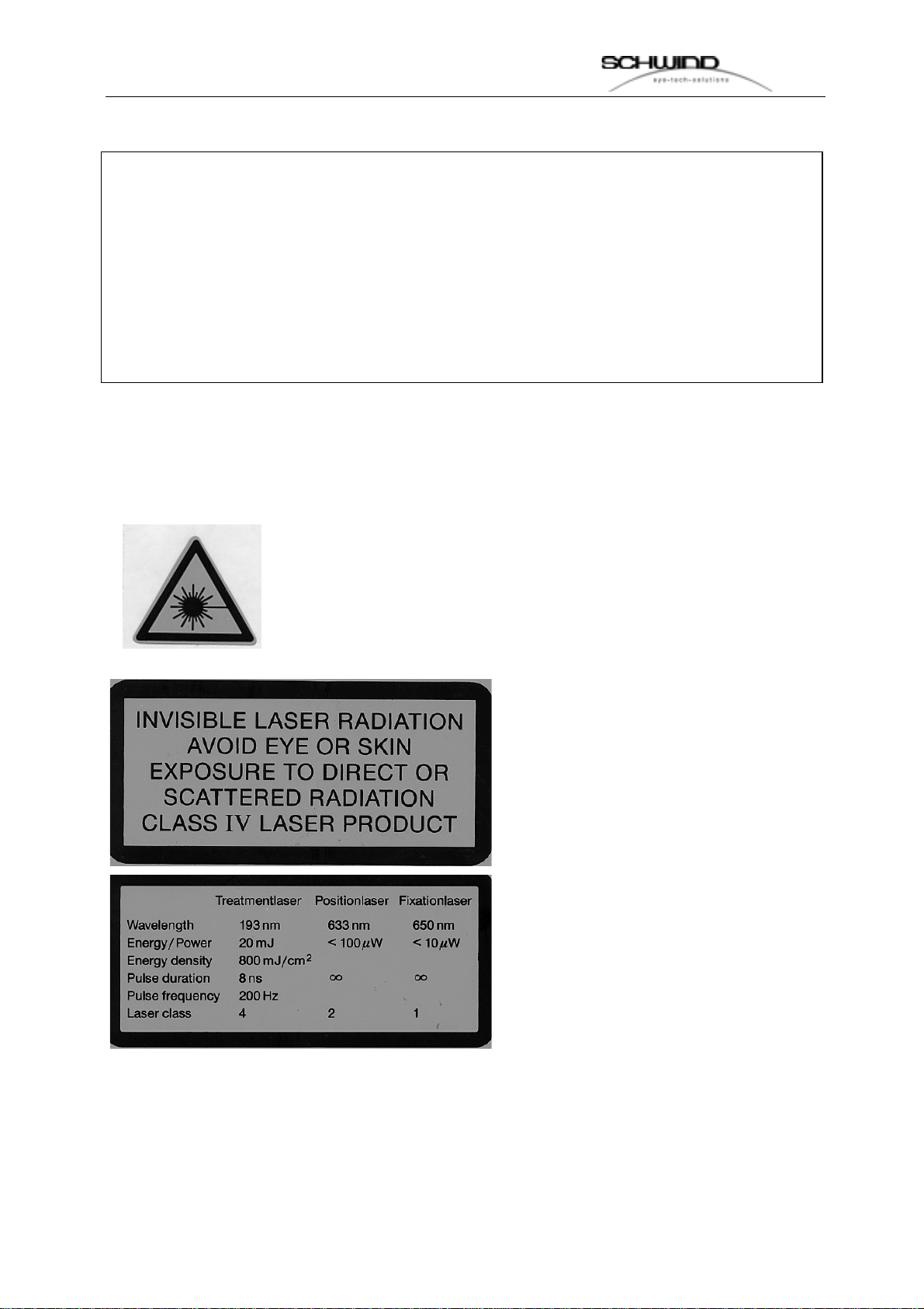
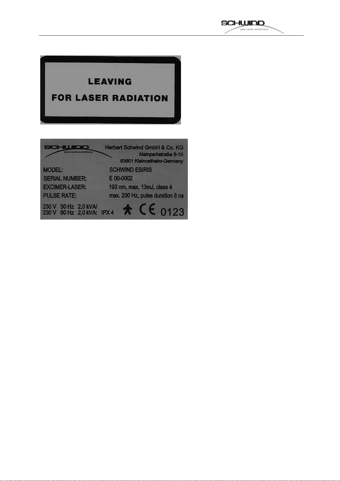
Alarm Shields and Type Shield............................................................................................................6
Accessible Beam Area.........................................................................................................................7
Protection Glasses...............................................................................................................................7
Working Gas........................................................................................................................................8
Gas containment:.................................................................................................................................8
DECLARATION OF MANUFACTURER (MPG)......................................................................................9
2. DESCRIPTION ..................................................................................................................................10
SPECIFICATION ........................................................................................................................................10
EXCIMER-LASER ......................................................................................................................................12
GAS SUPPLY............................................................................................................................................13
GASCONTAINMENT:..................................................................................................................................13
DELIVERY SYSTEM...................................................................................................................................14
MICROSCOPE AND ILLUMINATION ..............................................................................................................14
CONTROLLING..........................................................................................................................................15
PATIENT BED...........................................................................................................................................15
FOOT SWITCH..........................................................................................................................................15
RINSING OF OPTICAL BEAM DELIVERY SYSTEM .........................................................................................15
3. INSTALLATION REQUIREMENTS AND PREPARATIONS.............................................................17
WORKING ROOM......................................................................................................................................17
DIMENSIONS ESIRIS................................................................................................................................18
INPUT REQUIREMENTS .............................................................................................................................19
INSTALLATION AND ROOM PREPARATIONS FOR THE INSTALLATION...............................................................20
Minimum room dimensions (or room requirements)..........................................................................20
FLOOR REQUIREMENTS ............................................................................................................................20
INSTALLATION REQUIREMENTS .................................................................................................................20
Laser warning lamp ...........................................................................................................................21
Dimensions of boxes for the delivery.................................................................................................21
DELIVERY ................................................................................................................................................22
4. SOFTWARE DESCRIPTION BY SERVICE LOGIN..........................................................................23
MENU EXTRA ...........................................................................................................................................23
Menu Logfile ......................................................................................................................................23
Menu Parameter................................................................................................................................24
Distributor adress...............................................................................................................................25
MENU SERVICE........................................................................................................................................27
Menu Laser:.......................................................................................................................................29
Menu Scanner: ..................................................................................................................................35
Menu digital inputs / outputs..............................................................................................................36
Gascontainment:................................................................................................................................39
MENU ADJUSTMENT:.................................................................................................................................40
Laser:.................................................................................................................................................40
MENU TECHNICAL SECUTITY CHECK (TSC)...............................................................................................44
5. UNPACKING AND CONTROLLING.................................................................................................45
PUTTING INTO OPERATION........................................................................................................................46
WARRANTY..............................................................................................................................................47
6. DISMANTLING OF THE ESIRIS-LASERS .......................................................................................48

S
SE
ER
RV
VI
IC
CE
E
M
MA
AN
NU
UA
AL
L
4 of
79
___________________________________________________________________________
_______
ESIRIS -- Version 1.0 Date: 22.09.00
REMOVAL OF GAS BOTTLES (PREMIX AND HELIUM) .....................................................................................48
6.2 UNPLUG ELECTRICAL CONNECTIONS OF PATIENT BED, CAN-BUS MODULE AND GASCONTAINMENT........52
6.3 DISMANTLING OF OPTICAL PARTS........................................................................................................54
Dismantling of microscope :...............................................................................................................54
Dismantling CCD camera tower: .......................................................................................................55
Dismantling Scanning mirror..............................................................................................................57
NITROGEN GAS CYLINDER................................................................................................................59
DISMANTLE MONITOR AND KEYBOARD..........................................................................................59
DISCONNECTION OF THE FLUENCE DETECTOR............................................................................61
DISMANTLING THE PATIENT BED ...............................................................................................................61
DISMANTLING LASER................................................................................................................................62
7 INSTALLATION OF THE ESIRIS-LASER .........................................................................................63
ASSEMBLING THE LASER ..........................................................................................................................63
ASSEMBLING OF THE PATIENT BED ...........................................................................................................63
ELECTRICAL CONNECTION OF PATIENT BED, CAN-BUS-MODULE AND GAS-CONTAINMENT.........................66
ASSEMBLING OF MONITOR AND KEYBOARD ...............................................................................................67
ASSEMBLING OF THE LASER BEAM DELIVERY SYSTEM...............................................................................68
Assembling the Microscope:..............................................................................................................68
Assembling CCD-Camera Tower ......................................................................................................69
Assembling the Scanner....................................................................................................................70
CONNECTION OF THE NITROGEN BOTTLE ..................................................................................................70
ASSEMBLING FLUENCE DETECTOR............................................................................................................71
CONNECTION OF THE GAS MANAGEMENT TO THE OPTEX LASER ................................................................71
8. ALIGNMENT OF THE ESIRIS...........................................................................................................73
APPENDIX.............................................................................................................................................74
APPENDIX A: CALCULATION BASIS............................................................................................................74
A1. Introduction..................................................................................................................................74
A2. Correction of Myopia...................................................................................................................75
APPENDIX B: BEAM DELIVERY SYSTEM.....................................................................................................76
B1. Optical System............................................................................................................................76

S
SE
ER
RV
VI
IC
CE
E
M
MA
AN
NU
UA
AL
L
5 of
79
___________________________________________________________________________
_______
ESIRIS -- Version 1.0 Date: 22.09.00
1. Security of Device (Laser beam)
General
The SCHWIND ESIRIS is working with a pulsed UV-Laser. The Laser belongs to
class 4, which is the one with the highest danger potential. In any case, exposition of
eye or skin through direct or scattered laser beams has to be avoided. A professional
instrument maintenance - done in the planned intervals - secures that unintended
beams can not be exposed of the unit.
Opening of the device is only allowed through trained technicians. All persons,
assisting the treatment or attending the procedure have to be informed about danger
potentials and have to wear protection glasses.
Besides the high-performance laser, the SCHWIND ESIRIS uses three diodelasers
as positioning and fixation device. The output of the fixation laser is below 10 µW.
Therefore it belongs to class 1, which allows an undefined exposition time of the eye.
The positioning lasers are used to adjust the exact working distance to the corneal
surface. Their output is 50 - 100 µW. As the beams are aimed in a angle to the eye,
an influence at the retina is impossible.
Warnings Laser beam
The laser emits high-performance beams:
Wave lengths: 193 nm
Pulse energy: max. 8 mJ
Energy density: 800 mJ/cm2
Laser beams with these data are potentially dangerous, but in our case, possible
danger is minimised through some details:
•the beam diverges after passing the ablation area, so only in this area a high
energy density exists.
•the beams are partially absorbed in the air
•the cornea does not reflect beam during treatment
These effects reduce the energy density of the beam quickly with growing distance to
the working area, which is about 280 mm under the beam output opening. In spite of
this, the following warnings have to be followed for a safety use:

S
SE
ER
RV
VI
IC
CE
E
M
MA
AN
NU
UA
AL
L
6 of
79
___________________________________________________________________________
_______
ESIRIS -- Version 1.0 Date: 22.09.00
• Never look into the laser beam!
• Never put your skin into the laser beam!
• Wear protection glasses
• Make sure, that no reflection devices are placed in the area of the
laserbeam
• Follow the instructions of the trade association VBG 93!
• Persons, not used with the lasers, have to be informed about possible
risks!
Alarm Shields and Type Shield
Beam output is marked with laser warning signs..1.2. Warnschilder
They are looking as following:

S
SE
ER
RV
VI
IC
CE
E
M
MA
AN
NU
UA
AL
L
7 of
79
___________________________________________________________________________
_______
ESIRIS -- Version 1.0 Date: 22.09.00
Accessible Beam Area
The beam area of the device is horizontal down from the output opening to the next
surface. Normally this is the patient bed or, in case of treatment, the patient eye.
Diameter of beam at the output opening is app. 1,0 mm. In the treatment area, which
is 290 mm under the output opening, the beam has a diameter of 1,0 mm. Output
and energy density of beam decreases accordingly with increasing distance from
treatment area.
Protection Glasses
All persons inside the room (except the patient) have to wear protection glasses
according to DIN EN 207, when the laser is working. These glasses must have
protection level 7 for beams of 193 nm. The operating surgeon can put-off the
glasses, when he looks through the microscope. The glass optics of the microscopes
weaken the laserbeam, so that the necessary protection level is achieved. Protection
level of glasses depends on maximum existing middle output density (at max. pulse
following frequency) or the maximal energy density. These values are 5 x 10² J/m2.

S
SE
ER
RV
VI
IC
CE
E
M
MA
AN
NU
UA
AL
L
8 of
79
___________________________________________________________________________
_______
ESIRIS -- Version 1.0 Date: 22.09.00
Working Gas
Danger through the working gas (fluoride 0.106 %, argon 3.33 % and neon 96.56 %)
has not to be feared.
The laser head contains only a small quantity of fluoride. It is checked according to
the pressure containment regulations. An unintentional output of working gas is very
unlikely. Fluoride can be recognised through its pungent smell, long before the
concentration will come to maximum allowed values for working places. In such
case, open the window, leave the room and call service department of your
distributor or directly
Gas containment:
Pressure gas bottle with working gas is stored inside a gas containment. This gas
containment is airtight and has a filter, which would absorb the fluoride in case of a
leak. For service demands, there is a pressure gas bottle with helium, stored inside
the gas containment too.

S
SE
ER
RV
VI
IC
CE
E
M
MA
AN
NU
UA
AL
L
9 of
79
___________________________________________________________________________
_______
ESIRIS -- Version 1.0 Date: 22.09.00
Declaration of Manufacturer (MPG)
The device has been developed according to the Medical Device Regulations MPG.
The named TÜV-office Munich mark: 0123 manufacturer Co. Herbert Schwind
GmbH is allowed to produce laser devices for medicine purposes and to put them
into circulation.
Conformity with the construction authorisation of the device according to the
MPBetreibV is ensured under the precondition, that
• delivery is done through SCHWIND or authorised distributor
• all service and maintenance works are only performed through authorised
personnel
• accessories, consumables and disposable are only allowed, if a completely
harmless use (safety-technique) is confirmed through a test of this device
performed by an authorised testing authority. This is especially important for
patient bed.

S
SE
ER
RV
VI
IC
CE
E
M
MA
AN
NU
UA
AL
L
10 of
79
___________________________________________________________________________
_______
ESIRIS -- Version 1.0 Date: 22.09.00
2. Description
Specification
Working Laser ArF-Excimer-Laser
• Wavelength 193 nm
• Power (average, beam output) 2 W max.
• Mode pulsed
• Pulse energy (beam output) 15 mJ max.
• Pulse frequency 200 Hz max.
• Pulse duration 8 ns
• Pulse-to-pulse stability < 5 %
• Power density <1,5 x 10⁵W/m2
• Energy density 800 mJ/cm2
• Beam diameter (output) 7 x 4 mm
• Treatment area app. 280 mm under beam output
• Beam diameter (treatment area) 1.0 mm max.
• Beam divergence 2 x 1 mrad
Pilotlaser Diodelaser
• Wavelength 635 nm
• Power (middle, beam output) < 100 µW
• Mode continued
Fixationlaser Diodelaser
• Wavelength 650 nm
• Power (average, beam output) < 10 µW
• Mode pulsed

S
SE
ER
RV
VI
IC
CE
E
M
MA
AN
NU
UA
AL
L
11 of
79
___________________________________________________________________________
_______
ESIRIS -- Version 1.0 Date: 22.09.00
Controlling Industry PC 586AT (or better)
• Hard Disc 13,6 GB (or more)
• Processor Pentium III 500 MHz or higher
• Memory 64 MB
• Monitor 12.1’’, VGA flat monitor
• Interlock 1 opener external
• Monitor output VGA socket
Cooling Air
• Cooling Circulation internal fan
Electrical Connection 3,5 kVA
• Voltage 230 V, 1 phase
• Protection 16 A, sluggish, C-character
• Frequency 50 Hz/60 Hz (switchable)
• Connecting Plug 3 pole CEKON (blue)
Dimensions and Weight
• Floor Space see next chapter
• Total weight appr. 400 kg

S
SE
ER
RV
VI
IC
CE
E
M
MA
AN
NU
UA
AL
L
12 of
79
___________________________________________________________________________
_______
ESIRIS -- Version 1.0 Date: 22.09.00
Excimer-Laser
Laser principal: Excimer gas lasers are stimulated with an electric pulse in a mixture
of rare gases and halogens. The output lifts the rare gas atoms to a higher energy
level, so that they reacts with the halogen molecules and connect, as ArF, XeCI or
KrCI. These special molecules, known as excimers, are stable only for a short time.
They destroy and put out a high ultraviolet beam. If the gas is arranged in an optical
resonator of two parallel mirrors, the laser effect is achieved and light impulses with
very high maximum outputs are beamed. The laser gas consumes itself partially
during the output and must be changed after 10 x 106impulses or after 2-3 days.
The ‘OPTEX’ laser used with the SCHWIND ESIRIS is produced by Lambda Physik,
Goettingen. It is a very compact unit, which is optimised in reliability and low gas
consumption. Above mentioned specifications describe the data of the laser and the
necessary voltage connections.
Picture 1: Optex-Laser
Power supply voltage: 230 V AC +/-10 %, 1 Phase
Frequency: 50 Hz or 60 Hz
Power Input: 1.5 kVA
Security for the phase: 6.3 A
Device connections acc. to IEC standard

S
SE
ER
RV
VI
IC
CE
E
M
MA
AN
NU
UA
AL
L
13 of
79
___________________________________________________________________________
_______
ESIRIS -- Version 1.0 Date: 22.09.00
Gas Supply
The noble gas mixture has to be received directly by SCHWIND or the responsible
SCHWIND dealer, because only by this purity ranks and strictly check criterions are
guaranteed. Otherwise damages to the system could be coursed. This is to fix into a
Service- and Maintenance-Agreement. The gas bottle will be changed by a
SCHWIND service engineer/technician or a trained service technician of a
SCHWIND dealer. If these instructions will not be kept any claims of guarantee and
responsibility laps.
Gascontainment:
The Laser operates with premixed PREMIX gas. The capacity of one bottle is
sufficient for about 12 months at standard operation (approx. 180 fillings).

S
SE
ER
RV
VI
IC
CE
E
M
MA
AN
NU
UA
AL
L
14 of
79
___________________________________________________________________________
_______
ESIRIS -- Version 1.0 Date: 22.09.00
Delivery System
The optical system for beam guiding and forming is flanged to the laser at the side of
beam output. The beam guide is angled three times to 90°, so that the patient bed
can be placed parallel to the laser. Output of treatment beam is horizontally down
collinearly with the optical axis of the video control system which is used for
centration and focussing.
The treatment area is about 290 mm under the beam output. Focusing of ablation
field and the centering at the eye is performed with two positioning lasers and a
video camera. At the monitor of the video computer a video picture with crosshair is
produced. The ablation field has a maximum diameter of 14.0 mm. Minimal ablation
diameter is 1.0 mm. These values as well as the centration of the field at the
crosshair can easily be checked, through ablation pulses at a piece of illuminated
photo paper or Kodak Wratten Filter.
Diode lasers with low energy are used as positioning laser. Therefore they are
directed punctually at the eye in an angle from left and right, so that the points do
cross at exact distance of focus. A diode laser beams through the optical axis of the
unit onto the eye. This is used as fixation target for the patient. The laser power is
below 10 µW, so that a longer lasting illumination at the eye would not cause any
danger.
Microscope and Illumination
For exact control of corneal surface a coaxial stereo microscope is used. It allows a
coaxial stereoscopic control of the eye, without the control beam path being guided
through the working optic of the device. Therefore very good quality of the stereo
picture is possible. Abrasion of the epithelium and LASIK can be performed under
optimal control conditions. Further the control of treatment result is possible.
The cross hair is only constructed for a magnification of 14x! If another
magnification is used this might result in a decentralised position.
For illumination of treatment area, a cold-light lamp is integrated into the unit. This
lamp can be adjusted in brightness with a potentiometer and if necessary, it can also
be switched-off. The light is directly provided from a ring formed positioning of the
lightening end of the fiber below the beam output opening.

S
SE
ER
RV
VI
IC
CE
E
M
MA
AN
NU
UA
AL
L
15 of
79
___________________________________________________________________________
_______
ESIRIS -- Version 1.0 Date: 22.09.00
Controlling
The system controlling is located inside the device tower besides the patient bed. It
includes all voltage delivery units, input fuses and the control computer. Monitor and
using keyboard are located at the front-wall of the ESIRIS.
The controller can easily interact with the SCHWIND ESIRIS through input keyboard
and monitor. Inputs into the computer are menu controlled, so that input mistakes
can be avoided mostly. Release of treatment procedure is done with the footswitch.
Patient Bed
The patient bed should enable a simple way of exact and stable storing of the patient
as well as the adjustment of the treated eye at the ablation area.
Foot Switch
The footswitch is used to release the treatment procedure. This switch has two
switch points to avoid unintentional release of pulses. The treatment procedure can
be interrupted any time by releasing the footswitch. The program remains active, so
the treatment can be continued afterwards by pushing the footswitch again.
Rinsing of Optical Beam Delivery System
Radiation of ArF Excimer laser is 193 nm, and so it is at the outer limit of spectrum
area of ultra violet that is air transmitted. Partially absorption through air oxygen
lowers the radiation noticeably and ozone is produced. This would damage the
optical components, if it would accumulate inside the delivery system. Based on this,
it is useable to flood the way of radiation with an oxygen poor gas, which is also good
transparent at 193 nm.
For rinsing, nitrogen with a quality of 5.0 has been proved as very good. Nitrogen can
be stored and transported easily in pressure bottles, is in a low price limit and non-
toxic.
For optimising consumption of rinsing gas, the gas flow is controlled automatically
inside the containment of optical system. A flow control checks the nitrogen flow. If
the gas is getting empty inside the pressure bottle, the monitor of the control unit
displays a message.

S
SE
ER
RV
VI
IC
CE
E
M
MA
AN
NU
UA
AL
L
16 of
79
___________________________________________________________________________
_______
ESIRIS -- Version 1.0 Date: 22.09.00
Unit can not be used anymore in this case. The pressure bottle with nitrogen has to
be changed immediately. To avoid a slow loss of nitrogen through little leaks at the
valve of the bottle, it should be closed, while the ESIRIS is not in use. Often, the
above mentioned message appears, when opening of the valve had been forgotten.
Important note:
Flow of nitrogen must be 8 l/min, in order to
guarantee constant ablation values.

S
SE
ER
RV
VI
IC
CE
E
M
MA
AN
NU
UA
AL
L
17 of
79
___________________________________________________________________________
_______
ESIRIS -- Version 1.0 Date: 22.09.00
3. Installation requirements and preparations
Installation of SCHWIND ESIRIS is performed through trained service personnel. To
enable a proper installation, some prerequisites have to be fulfilled, which are
described below:
Working Room
The room, where ESIRIS will be installed, should have a minimum of 3 x 4 m (12
m²). At the outer side of the entrance door, a laser warning lamp and the official
laser warning symbol have to be installed. The warning lamp has to lighten, during
the laser is in use. A switch, which interrupts the laser, if the door is opened, can be
connected through the interlock input at the device. But this is only recommended
when it is guaranteed, that the door is not opened during treatment.
Inside the laser room explosive or inflammable material must not be stored. Near the
opening door, protection glasses according to DIN EN 207 have to be available in
sufficient quantity. (Protection glasses have to be available in following
specifications: D L9 / IL2 calculated by DIN EN 207, according to Laser Vision).
Nitrogen gas bottles, necessary for use of the laser can be stored inside the laser
room. They must be fixed, to avoid falling down.
Important note:
Do not use any liquid containing ammoniac to clean the room. Ammoniac
vapours attenuate the laser energy and create varying ablation rates and
treatment results!

S
SE
ER
RV
VI
IC
CE
E
M
MA
AN
NU
UA
AL
L
18 of
79
___________________________________________________________________________
_______
ESIRIS -- Version 1.0 Date: 22.09.00
Dimensions ESIRIS
Picture 2: Dimenstions ESIRIS upside

S
SE
ER
RV
VI
IC
CE
E
M
MA
AN
NU
UA
AL
L
19 of
79
___________________________________________________________________________
_______
ESIRIS -- Version 1.0 Date: 22.09.00
Picture 3: Dimensions ESIRIS front
Picture 4: Dimensions ESIRIS side
Input Requirements
SCHWIND ESIRIS needs as electrical input.
Electric connections 1,2 kVA
- Power supply voltage 230 V, 1 phase
- Fuse protection 16 A, slow; C-characteristic
- Frequency 50/60 Hz
- Connections 3-pol CEKON (blue)

S
SE
ER
RV
VI
IC
CE
E
M
MA
AN
NU
UA
AL
L
20 of
79
___________________________________________________________________________
_______
ESIRIS -- Version 1.0 Date: 22.09.00
Installation and room preparations for the installation
Minimum room dimensions (or room requirements)
appr. 3 m x 4m (12 m²)
Picture 5: Room requirements or room dimentions ideally (12
m²)
Requirements for the floor can be seen in above ground plan drawing.
Floor requirements
• Laser system and beam delivery system 250 kg
• Point weight through supporting feet at the laser max. 75 kg
• Base of supporting feet appr. 28 cm2 per support
• Patientbed 220 kg
• No. of supporting feet for the laser: 4
• No. of supporting feet for the patient bed: 4
• Door width: min. 80 cm
• Floor covering: PVC or stable, vibration free underground
Installation Requirements
• Stable, unyielding vibration free underground (no carpet)
Table of contents
Other SCHWIND Medical Equipment manuals
Popular Medical Equipment manuals by other brands

Circadiance
Circadiance SmartMonitor 2 PS checkout procedure

Invacare
Invacare Alternating Pressure Air Mattress MNS400-B Specification sheet

SmartLine Medical
SmartLine Medical SmartLift UNIVATOR user manual

Envitec
Envitec PhysioQuant user manual

Stryker
Stryker Isolibrium 2971 Operation manual

Energy-Laser
Energy-Laser L500 PRO user manual

Atmos
Atmos LC 27 operating instructions

FMS
FMS Solo Quick setup guide

Chattanooga Group
Chattanooga Group FLUIDC DHT 1480 Service manual

AKW MediCare
AKW MediCare Euro GW90 Gravity Waste Installation and user care instructions

Stealth Products
Stealth Products i2i owner's manual

Shenzhen Creative Industry Co.
Shenzhen Creative Industry Co. Oxy-One Plus user manual