OZGENC MAKINA OMRM-136 User manual

M.S.K. MOTOR KOMPRESÖR MAKINA SAN. TIC. LTD. STI.
Nilufer Organize Sanayi Bolgesi 113. Sk. No: 23 Nilüfer
Bursa Turkey 16140
Tel : +90 224 411 07 45
Fax : +90 224 411 07 49
PRODUCT AND MAINTENANCE MANUAL
CORNER CRIMPING
MACHINE
Model No. OMRM - 136
YOUR OZGENC DISTRIBUTOR IS:

Page 1 / 38
1
INTRODUCTION
CONTENT
1. INTRODUCTION ............................................................................................................................... 3
2. SAFETY MEASURES .......................................................................................................................... 4
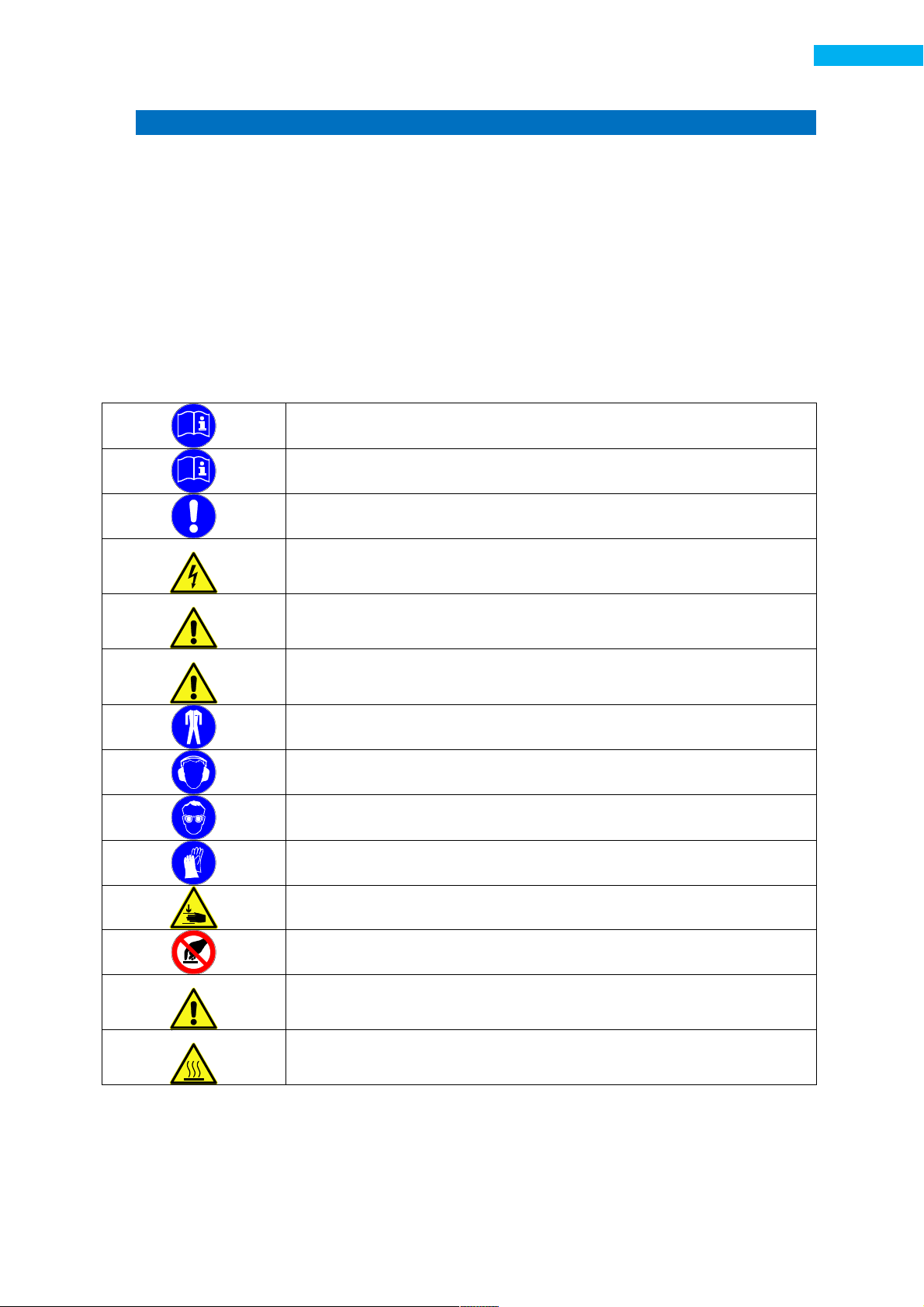
2.1 SYMBOLS USED IN THIS MANUAL ........................................................................................... 4
2.2 SAFETY INSTRUCTION .............................................................................................................. 5
3. MACHINE DESCRIPTION .................................................................................................................. 7
3.1 GENERAL IEW ........................................................................................................................ 7
3.2 TECHNICAL DESCRIPTION ........................................................................................................ 8
3.3 TECHNICAL SPECIFICATIONS .................................................................................................... 8
3.4 PACKAGE CONTENTS ............................................................................................................... 8
4. INSTALLATION ................................................................................................................................. 9
4.1 TRANSPORTATION DIRECTIONS .............................................................................................. 9
4.2 REQUIRED WORKING AREA ..................................................................................................... 9
4.3 INSTALLATION AND MOUNTING ........................................................................................... 10
4.4 INITIAL CONNECTION ............................................................................................................ 10
5. OPERATING PRINCIPLE .................................................................................................................. 11
5.1 MACHINE BASIC SETTINGS .................................................................................................... 11
5.1.1 ADJUSTMENT OF CRIMPING HEADS POSITION ............................................................. 12
5.1.2 ADJUSTMENT OF CRIMPING HEADS POSITION ............................................................. 12
5.1.3 BLADE INSTALLATION .................................................................................................... 13
5.1.4 BLADES FABRICATION DRAWING .................................................................................. 14
5.1.5 ADJUSTING THE BLADES ................................................................................................ 15
5.1.6 ADJUSTING THE CORNER STOP ..................................................................................... 18
5.1.7 LOCK STOP ADJUSTMENT .............................................................................................. 19
5.2 MACHINE CONTROLS............................................................................................................. 20
5.3 SWITCHING THE MACHINE ON .............................................................................................. 21
6. SER ICING AND LUBRICATING THE MACHINE .............................................................................. 23
6.1 OIL REPLENISHER ................................................................................................................... 23
6.1.1 OILS RECOMMENDED FOR THE USE IN REPLENISHER ................................................... 23
6.2 REGULAR LUBRICATION POINTS............................................................................................ 24
6.2.1 OILS RECOMMENDED FOR REGULAR LUBRICATION ..................................................... 24
7. PNEUMATIC COMPONENTS .......................................................................................................... 25
7.1 AL E AND CYLINDER INSPECTION ....................................................................................... 25
7.2 ADJUSTING THE PNEUMATIC CYLINDER TRA EL SPEED ....................................................... 26
7.3 LUBRICATOR .......................................................................................................................... 26
7.3.1 WHAT LUBRICATOR IS NECESSARY FOR ........................................................................ 27

Page 2 / 38
2
INTRODUCTION
7.3.2 OILS RECOMMENDED FOR LUBRICATOR USE ............................................................... 28
8. TROUBLESHOOTING ...................................................................................................................... 29
8.1 WHAT TO DO IF A MALFUNCTION IS PRESENT...................................................................... 29
8.2 PROBLEM – CAUSE – SOLUTION TABLE ................................................................................. 29
9. CIRCUIT DIAGRAMS ....................................................................................................................... 30
9.1 PNEUMATIC CIRCUIT ............................................................................................................. 30
10. PARTS LIST ................................................................................................................................. 31
10.1 MECHANICAL PARTS .............................................................................................................. 31
10.1.1 MAIN ASSEMBLY ............................................................................................................ 31
10.1.2 BODY .............................................................................................................................. 33
10.1.3 LOWER ASSEMBLY ......................................................................................................... 34
10.1.4 CORNER STOP ................................................................................................................ 35
10.1.5 CRIMPING HEAD ............................................................................................................ 36
11. WARRANTY ................................................................................................................................ 37

Page 3 / 38
3
INTRODUCTION
1. INTRODUCTION
We congratulate you on acquisition of the high-quality equipment. Undoubtedly, you have made a
correct and well-founded choice, production of our company is the highly reliable product corresponding to the
European quality standards. The equipment is simple in usage, has high consumer properties and will serve you
long.
User instruction contains the manufacturer states principles of work and machine use. Each operator,
beginning to work on the machine should familiarise attentively with the instruction and understand it.
t correct operation and observance requests of the present instruction the manufacturer guarantees
working capacity of the machine during a warranty period.
MANUFACTURER:
M.S.K. MOTO KOMP ESÖ MAKINA SAN. TIC. LTD. STI.
Nilufer Organize Sanayi Bolgesi 113. Sk. No: 23 Nilüfer
Bursa Turkey 16140
Tel : +90 224 411 07 45
Fax : +90 224 411 07 49
Some operational characteristics of the machine may not be specified herein.
We have performed numerous checks to verify the information given herein. However,
presence of some inconsistency is possible and complete conformance is not
guaranteed.
The producer reserves the right to modify process of production and instructions.

Page 4 / 38
4
SAFETY MEASURES
2. SAFETY MEASURES
1. Operation of the machine shall be performed by the operator only.
2. Operate the machine only after you have thoroughly understood all the designations and
definitions pertaining to safety.
3. The operator, who did not read or understand this manual, may not work on or operate this
machine.
4. Knowledge and understanding of this manual is important to prevent injury to the operator
and damage to third parties, animals, environment and machine itself.
Do not operate the machine without observing all the provisions mentioned above because such
operation is undoubtedly dangerous!
2.1 SYMBOLS USED IN THIS MANUAL
Indication of information necessary to familiarize the user with the
machine.
Indication of necessity of consulting the manual before operating the
machine.
Indication of the safety guidelines to be observed in order to prevent
possible damage to the machine.
Warning of high voltage present.
Warning of possible injury and any kind of temporary damage.
Warning of possible emergencies causing injury or death.
Indication of necessity to wear protective clothing
Indication of necessity to wear hearing protection while operating the
machine.
Indication of necessity to wear eye protection while operating the
machine.
Indication of necessity to wear gloves while operating the machine.
Warning of possible hand injury when it is jammed.
Prohibitive sign. Do not touch. Dangerous.
Warning to perform certain measures before servicing the machine.
Warning of high temperature present.

Page 5 / 38
5
SAFETY MEASURES
2.2 SAFETY INSTRUCTION
ATTENTION! It is mandatory to read the manual and understand all rules
and provisions.
Keep the manual in a safe place. The manual shall be within easy reach in
order to be consulted while servicing the equipment.
The person performing the installation of the machine shall thoroughly
read and understand this manual.
The operator is prohibited to perform repairs in case of machine
malfunction. The malfunction repair shall be performed by service
professional only.
The machine and its parts shall be protected from any external actions.
Check the lubricator regularly and top off the oil if necessary.
It is not prohibited to be under the machine during the loading and
unloading.
The machine shall be grounded. Operation without grounding is
prohibited!
Eye protection shall be used while machine operation.
Hearing protection shall be used against the equipment noise.
Gloves shall be worn while changing the discs.
Only original spare parts shall be used.
Take care of the control panel. Make sure that it is protected from any
mechanical damage.
Start-up of the equipment shall be performed only by the service
professional. Start-up by any other person is prohibited.
Equipment repairs shall be performed only by service professionals and
only with genuine spare parts and consumables.
Usage of the equipment for purposes other than its intended use may
cause dangerous situations.
Always pay attention and check what you do, do not start the machine
operation without thinking. Operation of the machine is prohibited if you
are tired or under influence of drugs, alcohol or medications. А minor
inattention while operating the machine may cause major injuries.
Operation of the machine with damaged power cable is prohibited. The
damaged cable shall be replaced as soon as possible.
Use special work clothes. Do not wear loose
-
fitting clothing or jewelry.
Watch out for hair, clothing and gloves around moving parts. Loose-fitting
clothing, jewelry or long hair may be caught in the moving parts of the
machine.
Power and air supply shall be switched off before performing any repairs
or maintenance.
Removal of protection compo
nents of the machine is prohibited. It shall
be remembered that machine protection components are installed there
to ensure the safe operation of the machine.

Page 6 / 38
6
SAFETY MEASURES
Avoid jamming your hands between profile fixing cylinders and moving
parts of the equipment.
Do not open the protective covers until the machine is fully switched off.
Only one operator shall work with the machine.
The machine shall undergo regular maintenance and adjustment. Do not
operate the machine if it is out of order.
Do not operate the machine in wet or damp environments.
Touching the heating plate of the machine in operation, as well as
touching the plate when it is heated, is prohibited.

Page 7 / 38
7
MACHINE DESCRIPTION
3. MACHINE DESCRIPTION
3.1 GENERAL VIEW
Figure 3.1-1 General view
1. Corner crimping pedal.
2. Lock stop activation pedal.
3. Side stops.
4. Right crimping head.
5. Corner stop horizontal adjustment knob.
6. Corner stop vertical adjustment knob.
7. Left crimping head.
8. Pneumatic clamps.
9. Supports.
10. Lock stop.
11. Adjustment knob for lock stop travel limiter.
10
4
3
2
1
9
8
5
ю
7
ю
6
ю
11

Page 8 / 38
8
MACHINE DESCRIPTION
3.2 TECHNICAL DESCRIPTION
- 2 universal knife-equipped, 3-axis adjustable heads
- pneumatic linkage-equipped clamps ensure synchronous head movement
- horizontal hydropneumatic retractable stop facilitates smooth profile movement and ensures
their proper alignment and locking
- vertical pneumatic clamps ensure proper insertion and locking of the profiles in the machine
- knife-equipped head assembly ensures micrometric adjustment
- quick lock/unlock system ensures full adaptability of the machine to any kind of profile
- profile alignment with the help side stops
- hydropneumatic stop locking
- two pedal operation
3.3 TECHNICAL SPECIFICATIONS
Air pressure : 6–8 Bar
Air consumption : 12 lpm
Crimping power : 3100 kg*f
Horizontal travel of crimping heads : 25 mm
ertical travel of crimping heads : 60 mm
Max blade height : 110 mm
Lock stop travel : 140 mm
Machine length : 900 mm
Machine width : 850 mm
Machine height : 1225 mm
Machine weight : 380 kg
3.4 PACKAGE CONTENTS
Machine : 1 pc.
Side support with support leg : 2 pcs
Air gun : 1 pc.
5 mm blade : 2 pcs.
6 mm blade : 2 pcs.
Electrical panel key : 1 pc.
Operator’s manual : 1 pc.
Technical data sheet : 1 pc.
Warranty card : 1 pc.
SPTA kit
8 mm Allen wrench : 1pc.
6 mm Allen wrench : 1pc.
5 mm Allen wrench : 1pc.
½ - Ø8 adapter : 1pc.
Ø8 hose : 3 m
Hose clamp : 2 pcs.

Page 9 / 38
9
INSTALLATION
4. INSTALLATION
The equipment has passed factory operational tests of all mechanical and pneumatic assemblies.
All materials and spare parts shipped from the factory were fully and thoroughly inspected before
delivery to the transport operator.
Please check and inspect the equipment on take-over for any damage taken in transit.
4.1 TRANSPORTATION DIRECTIONS
The machine is shipped in a special packaging. Pay attention to the leveling of the machine’s
position on the forklift’s forks. Positioning the forks as close to the ground as possible provides
balance and ensures good field of view for the forklift operator. The forks shall be adjusted for
maximum spacing width and the machine situated in the center.
1. Damage of the cables, cylinders, hoses, lubricator and control panel shall be avoided when
loading the forklift.
2. Means of transport shall be appropriately sized for the machine.
3. Avoid hitting the machine while moving it.
4. The machine shall be moved by the forklift truck.
4.2 REQUIRED WORKING AREA
To ensure high performance of the machine, it is recommended to place the machine in the shop
while observing the manufacturer recommended clearances. Minimum top clearance between the
topmost machine part and the ceiling is 2m.
Figure4.2-1 Required working area
1
5
00 mm
2000 mm
1000 mm
1
5
00 mm

Page 10 / 38
10
INSTALLATION
4.3 INSTALLATION AND MOUNTING
Make sure the surface and base is even and strong. Make sure there is
enough space around the machine for safe operation, servicing and turn.
Use level while installing the machine. When the machine is in balanced
position then vibrations are decreased, it becomes simpler to operate,
performance and performance quality are increased.
Air pressure shall be 6
-
8Bar. Thick hose prevents the pressure drop
throughout the line. Moreover, moisture ingress shall be avoided to
prevent pneumatic cylinders and valves breakage.
Warning: If air s pply connection does not incl de deh midifier then
pne matic valves are not s bject to warranty service!
4.4 INITIAL CONNECTION
1. Remove the packaging.
2. Position the machine on even horizontal surface.
3. Connect the air supply (6-8 Bar).
4. Check the lubricator oil level.
The initial connection shall be performed by the technical support service. The manufacturer
assumes no liability for the damage caused by connecting the machine by personnel other than
service department personnel.
Initial connection by the service department personnel
• Repair the malfunctions resulting from transport
• Check the leveling of the installed machine
• Check the electrical and air connections
• Switch the machine on
• Brief the operator
• Give directions on safety and maintenance

Page 11 / 38
11
OPERATING PRINCIPLE
5. OPERATING PRINCIPLE
5.1 MACHINE BASIC SETTINGS
The machine has been factory preset. Regular wear and tear of the mechanical parts and assemblies
and profile system changes require changing of some settings. The necessary settings are indicated
below.
Figure5.1-1
1. Adjustment knob of lock stop travel limiter.
2. Horizontal adjustment knob of corner stop.
3. ertical adjustment knob of corner stop.
4. Adjustment knob of top pneumatic clamp.
5. Adjustment knob of side stop.
6. Adjustment knob of clamping head travel.
7. Adjustment screw of crimping head.
1
2
3
4
5
6
7

Page 12 / 38
12
OPERATING PRINCIPLE
5.1.1 ADJUSTMENT OF CRIMPING HEADS POSITION
Figure5.1-2 5.1.1 Adjusting crim ing head osition
The operation is the same for both heads
1. Loosen the fixing bolts.
2. Turn the knob to achieve the desired position. Tighten the bolts (1) when operation is
finished.
5.1.2 ADJUSTMENT OF CRIMPING HEADS POSITION
Figure 5.1-3 Adjustment of crim ing heads osition
The operation is the same for both heads
1. Loosen the fixing bolt.
2. Insert the allen wrench and turn until the head is in the desired position. Tighten the bolt (1)
when operation is finished.
1
2
1
2

Page 13 / 38
13
OPERATING PRINCIPLE
5.1.3 BLADE INSTALLATION
Blade is a rectangular steel bar used as a striking blade. The blade breaks through the aluminum
profile walls driving them into the steel insert.
Figure5.1-4 5.1.3 Blade installation
Fully disconnect the air supply before installing the blades!
The operation is the same for both heads
1. Loosen the fixing bolts by turning the wrench to direction shown by the arrow.
2. Install the blades. Tighten the bolts.
3. The installation groove is fitted with magnetic insert to facilitate the installation of the
blades.
1
2

Page 14 / 38
14
OPERATING PRINCIPLE
5.1.4 BLADES FABRICATION DRAWING
Figure 5.1-5 Blade installation groove. Crim ing head to view
Figure 5.1-6 Blade base drawing
Figure 5.1-7 Blade base thickness
Recommended blade base thickness – 14 mm
Figure 5.1-8 Blade end view
1. Both edges contacting the profile shall be sharp.
Blade
are made of
steel
tool
(DIN 1.2379)
with
hardness
58
–
60 HRC,
tempered
in vacuum
furnance with nitrogen.
Blades are fabricated for specific profile series!
1

Page 15 / 38
15
OPERATING PRINCIPLE
5.1.5 ADJUSTING THE BLADES
Figure 5.1-9 Size “А”
The frame and leaf components are connected by inserts. The inserts connect only aluminum
compartments – they are not inserted into heat barrier compartments.
Figure 5.1-10 Insert sam le
When switching to another profile system, machine settings shall be changed.
45°
profile
Insert

Page 16 / 38
16
OPERATING PRINCIPLE
1.
Place the insert
into profiles cut
at 45°, use caliper
to measure “А”
size.
Figure5.1-11
2.
Mark the
“
А
”
size
on both sides of
the profiles.
Figure5.1-12
3.
B
ear
the profiles
against the
corner stop.
4. Press the No.2
pedal. The lock
stop and
pneumatic
clamps will lock
the angle.
5. Press on the No. 1
pedal and trace
the blade contact
points.
Figure 5.1-13 Blade contact oints

Page 17 / 38
17
OPERATING PRINCIPLE
6.
While crimping,
the blades shall
slide exactly on
the edge of the
insert groove. The
blade contact
point shall
correspond with
the “А” size.
7. In case the blade
contact point
does not match
the “А” size,
corner stop
position shall be
adjusted.
A
Figure 5.1-14

Page 18 / 38
18
OPERATING PRINCIPLE
5.1.6 ADJUSTING THE CORNER STOP
1.
Deactivate the
lock stop by
pressing pedal
No.2.
2. Loosen the corner
stop fixing bolts.
Figure 5.1-15
3.
Use the
adjustment knob
to set the desired
corner stop
position.
4. Tighten the corner
stop bolts.
Figure 5.1-16
5.
After
each
change
of settings,
adjustment of the
side stops to new
profile position is
necessary.
Figure 5.1-17 Side sto

Page 19 / 38
19
OPERATING PRINCIPLE
5.1.7 LOCK STOP ADJUSTMENT
1.
In order
so
the
lock stop do not
over squeeze the
profile, travel
limiter needs to
be adjusted
properly.
2. When properly
adjusted, the lock
stop equally
bears against the
profile and the
limiter.
Figure 5.1-18
Figure 5.1-19
3.
Lock stop
shall
bear against the
rigid edge of the
profile.
4. To adjust the lock
stop height,
insert the allen
wrench and set
the desired
position.
Figure 5.1-20
Table of contents
Popular Crimping Tools manuals by other brands

DMC
DMC DCTE4B quick start guide

molex
molex 63825-7570 Specification sheet

Stanley
Stanley DUBUIS KW Hydraulik BPE130 instruction manual

Hubbell
Hubbell BURNDY PATRIOT 81K2 Series SAFETY OPERATING & MAINTENANCE INSTRUCTIONS

Cembre
Cembre RHC131LN-KV Operation and maintenance manual

JST
JST CS 10 L-WC-SF371 instruction manual