Ozito OBD2 User manual

AUTO
SCANNER
OBD2/EOBD Code Reader
[ ] = SetuP
[ ] = Scan
OBDII
AUTO
SCANNER
OBD2/EOBD Code Reader
[ ] = SetuP
[ ] = Scan
OBDII
AUTOMOTIVE
SCAN TOOL
OBD2 CODE READER
INSTRUCTION MANUAL
SPECIFICATIONS
Support: OBD2 Compliant Vehicles
Input: 8V to 25V
Operating Temp.: 0°C~50°C
Storage Temp.: –20°C~70°C
Display: 128 x 64mm Backlit LCD
Weight: 0.15kg
OAST-050
STANDARD EQUIPMENT
3 YEAR REPLACEMENT WARRANTY*
Your product is guaranteed for a period of 36 months from the original date of purchase. If
a product is defective it will be replaced in accordance with the terms of this warranty. Warranty
excludes consumable parts, for example: .
*This product is intended for DIY use only and replacement warranty covers domestic use.
WARNING
The following actions will result in the warranty being void.
• If the tool has been operated on a supply voltage other than that specified on the tool.
• If the tool shows signs of damage or defects caused by or resulting from abuse, accidents
or alterations.
• Failure to perform maintenance as set out within the instruction manual.
• If the tool is disassembled or tampered with in any way.
• Professional, industrial or high frequency use.
WARRANTY
OZITO Australia/New Zealand (Head Office) 25 Fox Drive Dandenong South, Victoria, Australia 3175.
ozito.com.au
Automotive Scan Tool
0921
IN ORDER TO MAKE A CLAIM UNDER THIS WARRANTY
YOU MUST RETURN THE PRODUCT TO YOUR NEAREST
BUNNINGS WAREHOUSE WITH YOUR BUNNINGS
REGISTER RECEIPT. PRIOR TO RETURNING YOUR
PRODUCT FOR WARRANTY PLEASE TELEPHONE OUR
CUSTOMER SERVICE HELPLINE:
Australia: 1800 069 486
New Zealand: 0508 069 486
The benefits provided under this warranty are in addition to other rights and remedies which
are available to you at law.
Our goods come with guarantees that cannot be excluded at law. You are entitled to a
replacement or refund for a major failure and for compensation for any other reasonably
foreseeable loss or damage. You are also entitled to have the goods repaired or replaced if the
goods fail to be of acceptable quality and the failure does not amount to a major failure.
Generally you will be responsible for all costs associated with a claim under this warranty,
however, where you have suffered any additional direct loss as a result of a defective product
you may be able to claim such expenses by contacting our customer service helpline above.
TO ENSURE A SPEEDY RESPONSE PLEASE HAVE
THE MODEL NUMBER AND DATE OF PURCHASE
AVAILABLE. A CUSTOMER SERVICE REPRESENTATIVE
WILL TAKE YOUR CALL AND ANSWER ANY QUESTIONS
YOU MAY HAVE RELATING TO THE WARRANTY POLICY
OR PROCEDURE.

AUTO
SCANNER
OBD2/EOBD Code Reader
[ ] = SetuP
[ ] = Scan
OBDII
12V AUTOMOTIVE SCAN TOOL
KNOW YOUR PRODUCT
1. KNOW YOUR PRODUCT OVERVIEW
ONLINE MANUAL
Scan this QR Code with your mobile
device to take you to the online manual.
1. Backlit LCD
2. Red LED
3. Yellow LED
4. Green LED
5. Up Button
6. Back Button
7. OBD2, 16-Pin Connector
8. Down Button
9. OK Button
4
5
1
2
3
6
7 8 9
1. Backlit LCD
Indicates setup, scan, menu options and test results.
2. Red LED
Indicates there is a problem in one or more of the vehicle’s
systems. The red LED is also used to show that DTCs are present.
DTCs are shown on the Scan Tool’s display. In this case, the MIL
lamp on the vehicle’s instrument panel will light steady on.
3. Yellow LED
Indicates there is a possible problem. A “Pending” DTC is present
and/or some of the vehicle’s emission monitors have not run their
diagnostic testing.
4. Green LED
Indicates that engine systems are running normally (The number
of monitors on the vehicle which are active and performing their
diagnostic testing is in the allowed limit, and no DTCs are present).
5. Up Button
Scrolls up through menu items
6. Back Button
Returns to previous menu.
7. OBD2 16-Pin Connector
Connects the scan tool to the vehicle’s Data Link Connector (DLC).
Your DLC is usually located near centre under the instrument
panel (dash), under or around the driver’s side of most vehicles.
Do not force OBD2
Connector into the
DLC, ensure the
connector is in the
correct orientation
to the DLC to avoid
damaging the pins.
Note: Refer to your
vehicle’s service
manual for the
location if the DLC
cannot be found.
8. Down Button
Scrolls down through menu items.
9. OK Button
Confirms a selection (or action) from a menu item.
SETUP & PREPARATION

2. GENERAL INFORMATION
OBD2 Readiness Monitors
An important part of a vehicle’s OBD2 system is the Readiness
Monitors, which are indicators used to find out if all of the
emissions components have been evaluated by the OBD2
system. They are running periodic tests on specific systems and
components to ensure that they are performing within allowable
limits.
Currently, there are eleven OBD2 Readiness Monitors (or
I/M Monitors) defined by the U.S. Environmental Protection
Agency(EPA). Not all monitors are supported by all vehicles and
the exact number of monitors in any vehicle depends on the motor
vehicle manufacturer’s emissions control strategy.
•Continuous Monitors – Some of the vehicle components or
systems are continuously tested by the vehicle’s OBD2 system,
while others are tested only under specific vehicle operating
conditions. The continuously monitored components listed below
are always ready:
1. Misfire
2. Fuel System
3. Comprehensive Components (CCM)
Once the vehicle is running, the OBD2 system is continuously
checking the above components, monitoring key engine sensors,
watching for engine misfire, and monitoring fuel demands.
•Non-Continuous Monitors – Unlike the continuous monitors,
many emissions and engine system components require the
vehicle to be operated under specific conditions before the monitor
is ready. These monitors are termed non-continuous monitors and
are listed below:
1. EGR System 2. O2 Sensors
3. Catalyst 4. Evaporative System
5. O2 Sensor Heater 6. Secondary air
7. Heated Catalyst 8. A/C system
OBD2 Monitor Readiness Status
OBD2 systems must indicate whether or not the vehicle’s PCM’s
monitor system has completed testing on each component.
Components that have been tested will be reported as “Ready”, or
“Complete”, meaning they have been tested by the OBD2 system.
The purpose of recording readiness status is to allow inspectors
to determine if the vehicle’s OBDII system has tested all the
components and/or systems.
The powertrain control module (PCM) sets a monitor to “Ready” or
“Complete” after an appropriate drive cycle has been performed.
The drive cycle that enables a monitor and sets readiness codes to
“Ready” varies for each individual monitor. Once a monitor is set
as “Ready” or “Complete”, it will remain in this state. A number
of factors, including erasing of diagnostic trouble codes (DTCs)
with a scan tool or a disconnected battery, can result in Readiness
Monitors being set to “Not Ready”. Since the three continuous
monitors are constantly evaluating, they will be reported as
“Ready” all of the time. If testing of a particular supported non-
continuous monitor has not been completed, the monitor status
will be reported as “Not Complete” or “Not Ready”.
In order for the OBD monitor system to become ready, the vehicle
should be driven under normal operating conditions. These
operating conditions may include a mix of highway driving and
stop and go, city type driving, and at least one overnight-off period.
For specific information on getting your vehicle’s OBD monitor
system ready, please consult your vehicle owner’s manual.
OBD2 Definitions
• Powertrain Control Module (PCM) – OBD2 terminology for the
on-board computer that controls engine and drive train.
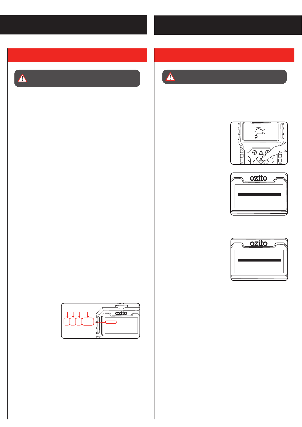
• Malfunction Indicator Light (MIL) – Malfunction Indicator Light
(Service Engine Soon, Check Engine) is a term used for the light
on the instrument panel. It is to alert the driver and/or the repair
technician that there is a problem with one or more of vehicle’s
systems and may cause emissions to exceed federal standards. If
the MIL illuminates with a steady light, it indicates that a problem
has been detected and the vehicle should be serviced as soon as
possible. Under certain conditions, the dashboard light will blink
or flash. This indicates a severe problem and flashing is intended
to discourage vehicle operation. The vehicle onboard diagnostic
system can not turn the MIL off until necessary repairs are
completed or the condition no longer exists.
• DTC – Diagnostic Trouble Codes (DTC) that identify which section
of the emission control system has malfunctioned.
• Enabling Criteria – Also termed Enabling Conditions. They are
the vehicle-specific events or conditions that must occur within the
engine before the various monitors will set, or run. Some monitors
require the vehicle to follow a prescribed “drive cycle” routine as
part of the enabling criteria. Drive cycles vary among vehicles and
for each monitor in any particular vehicle.
• OBD2 Drive Cycle – A specific mode of vehicle operation that
provides conditions required to set all the readiness monitors
applicable to the vehicle to the “ready” condition. The purpose
of completing an OBD2 drive cycle is to force the vehicle to run
its onboard diagnostics. Some form of a drive cycle needs to be
performed after DTCs have been erased from the PCM’s memory
or after the battery has been disconnected. Running through a
vehicle’s complete drive cycle will set the readiness monitors so
that future faults can be detected. Drive cycles vary depending
on the vehicle and the monitor that needs to be reset. For vehicle
specific drive cycle, consult the vehicle’s Owner’s Manual.
• Freeze Frame Data – When an emissions related fault occurs,
the OBD II system not only sets a code but also records a snapshot
of the vehicle operating parameters to help in identifying the
problem. This set of values is referred to as Freeze Frame Data and
may include important engine parameters such as engine RPM,
vehicle speed, air flow, engine load, fuel pressure, fuel trim value,
engine coolant temperature, ignition timing advance, or closed loop
status.

AUTO
SCANNER
1/4
Current DTC
P0115
Engine Coolant
Temperature Sensor 1
Circuit
P0115
1 2 3 4
AUTO
SCANNER
OBD2/EOBD Code Reader
[ ] = SetuP
[ ] = Scan
OBDII
AUTO
SCANNER
1/3
Tool Setup
Language
Unit of Measure
Contrast
AUTO
SCANNER
1/2
Select ECU
$7E8: Engine
$7E9: A/T
3. MENU 4 VEHICLE CONNECTION
OPERATION
The automotive scan tool is used to check engine of most OBD2
compliant vehicles from 1996 onwards with standard sized 16-Pin
Data Link Connector (DLC).
Function Description
•Dual-system diagnostic, optional engine and transmission.
•Quickly indicate engine faults, with green / yellow / red LED
indicators as fault lights.
•Read and clear the engine fault code and view Diagnostic
Trouble Codes (DTC) definitions.
•Display of sensor data stream information such as vehicle
revolutions per minute (rpm), engine coolant temperature in real
time.
•View freeze frame data and I/M (readiness monitor status
information.
•Read vehicle information:
vehicle identification number (VIN)
calibration identification numbers (ID’s)
calibration verification number (CVN’s)
•Multi- language
WARNING! READ AND UNDERSTAND THE WARNINGS
BEFORE SETUP.
Diagnostic Trouble Codes (DTC)
OBD2 Diagnostic Trouble Codes are codes that are stored by the
on-board computer diagnostic system in response to a problem
found in the vehicle. These codes identify a particular problem
area and are intended to provide you with a guide as to where
a fault might be occurring within a vehicle. OBD2 Diagnostic
Trouble Codes consist of a five-digit alphanumeric code. The
first character, a letter, identifies which control system sets the
code. The other four characters, all numbers, provide additional
information on where the DTC originated and the operating
conditions that caused it to set. See below example to illustrate
the structure of digits:
1. System
B = Body
C = Chassis
P = Powertrain
U = Network
2. Code Type
Generic = 0
Manufacturer Specific = 1
3. Sub-Systems
1 = Fuel and Air Metering
2 = Fuel and Air Metering
3 = Ignition System or Engine Misfire
4 = Auxiliary Emission Controls
5 = Vehicle Speed Control and Idle
Controls
6 = Computer Output Circuits
7 = Transmission Controls
8 = Transmission Controls
4. Identifying specific
malfunctioning section of
the systems
WARNING! DO NOT CONNECT OR DISCONNECT SCAN
TOOL WITH IGNITION ON OR ENGINE RUNNING.
Setup
1. Connect OBD2 16-pin connector into the DLC.
2. Turn the ignition on. Setup can be done with engine off or
engine running.
3. From the home screen, press
the “UP” button to enter the
Setup interface.
•Language: The default
language from the factory is
English, many other languages can
be manually selected.
•Unit of Measure: The default
units from the factory is metric,
imperial can me manually selected.
• Contrast: Backlight contrast is adjustable, factory default 25%
•System Section Module: If
more than one module is detected,
you will be prompted to select a
module before testing. Select the
desired module and press the “OK”
button to confirm.
4. Press the Back button when
setup is complete to return to the home screen.

AUTO
SCANNER
1/6
Diagnostic Menu
Read Codes
Erase Codes
Data Stream
Freeze Frame
I/M Readiness
Vehicle Information
AUTO
SCANNER
OBD2/EOBD Code Reader
[ ] = SetuP
[ ] = Scan
OBDII
AUTO
SCANNER
Entering System
### ###
Entering system,
Please wait....
AUTO
SCANNER
Monitor Status
Read Codes
DTCs in this ECU
Monitors OK
Monitors INC
Monitors N/A
Ignition Compression
0
0
0
10
AUTO
SCANNER
OBD2/EOBD Code Reader
[ ] = SetuP
[ ] = Scan
OBDII
AUTO
SCANNER
Entering System
### ###
Entering system,
Please wait....
AUTO
SCANNER
Monitor Status
Read Codes
DTCs in this ECU
Monitors OK
Monitors INC
Monitors N/A
Ignition Compression
0
0
0
10
AUTO
SCANNER
OBD2/EOBD Code Reader
[ ] = SetuP
[ ] = Scan
OBDII
AUTO
SCANNER
Entering System
### ###
Entering system,
Please wait....
AUTO
SCANNER
Monitor Status
Read Codes
DTCs in this ECU
Monitors OK
Monitors INC
Monitors N/A
Ignition Compression
0
0
0
10
AUTO
SCANNER
Read Codes
Read Codes
Current DTCs ($03)
Pending DTCs ($07)
Permanent DTCs ($0A
1/3
AUTO
SCANNER
1/4
Current DTC
P0115
Engine Coolant
Temperature Sensor 1
Circuit
AUTO
SCANNER
DTC num.
Read Codes
CT DTC: 00
PD DTC: 00
PT DTC 00
AUTO
SCANNER
Read Codes
Read Codes
Current DTCs ($03)
Pending DTCs ($07)
Permanent DTCs ($0A
1/3
AUTO
SCANNER
1/4
Current DTC
P0115
Engine Coolant
Temperature Sensor 1
Circuit
AUTO
SCANNER
DTC num.
Read Codes
CT DTC: 00
PD DTC: 00
PT DTC 00
AUTO
SCANNER
Read Codes
Read Codes
Current DTCs ($03)
Pending DTCs ($07)
Permanent DTCs ($0A
1/3
AUTO
SCANNER
1/4
Current DTC
P0115
Engine Coolant
Temperature Sensor 1
Circuit
AUTO
SCANNER
DTC num.
Read Codes
CT DTC: 00
PD DTC: 00
PT DTC 00
5. DIAGNOSTIC MENU
OAST-050
•Read Codes: Read the
diagnostic trouble code (DTC)
in the engine or transmission
system and display the standard
definition.
Ignition on, engine off or running
1. Use the “UP” and “DOWN”
buttons to select a Read Codes and press the “OK” button to
confirm.
If there are DTC’s, the backlit
LCD will display the number of
codes:
2. Press “OK” button
CT (Current) DTC codes- Are
generated by the current hardware
failure. The current fault code(s) for
the hardware failure are generated
by a continuous fault and can
only be cleared if the hardware is
repaired.
PD (Pending) DTC codes- They
indicate problems that the control
module has detected during the current or last driving cycle but
are not considered serious yet. Pending Codes will not turn on
the malfunction indicator lamp (MIL) unless the same problem is
detected again. If the fault does not occur within a certain number
of warm-up cycles, the code clears from memory.
PT (Permanent) DTC codes- These codes cause the control
module to illuminate the malfunction indicator light (MIL) when
emission-related fault occurs. These DTCs cannot be cleared until
it is confirmed that the problem is fixed.
2. Use the “UP or “DOWN” button to select Current, Pending or
Permanent codes from the Read Codes menu and press the
“OK” button. See Diagnostic Trouble Codes (DTC) heading in
this manual.
Note: If no DTCs, a “The vehicle has no fault codes” message
shows on the backlit LCD.
3. View the DTCs and their
definitions on the backlit LCD
Display. Press “BACK” button to
return to previous screen.
4. If more than one DTC is found,
the number to the right of the
backlit LCD indicates sequence
of DTCs. Use the “UP” and
“DOWN” button to check all the
codes.
Scan
Ignition on, engine running.
1. From the home screen, press
the “OK” button to enter the
Scan interface.
2. Wait for the menu to appear.
A sequence of messages
displaying the OBD2 protocols
and progress bar will be
observed on the backlit LCD
until the vehicle protocol is
detected.
3. View a summary of the system
status (MIL status, DTC counts,
Monitor status) on backlit LCD.
4. Press the “OK” button for
Diagnostic Menu
WARNING! OPERATE VEHICLE IN A WELL- VENTILATED
AREA, EXHAUST GASSES ARE POISONOUS.

1/2
AUTO
SCANNER
I/M Readiness
Since DTCs Cleared
This Drive Cycle
AUTO
SCANNER
I/M Readiness
MIL OFF
MIS OK
FUEL OK
CCM OK
CAT OK
HCAT N/A
1/2
1/2
AUTO
SCANNER
I/M Readiness
Since DTCs Cleared
This Drive Cycle
AUTO
SCANNER
I/M Readiness
MIL OFF
MIS OK
FUEL OK
CCM OK
CAT OK
HCAT N/A
1/2
Freeze Frame
01/01
DTCFRZF U3FFF
YES
NO
1/2
AUTO
SCANNER
Erase DTC
Read Codes
CT DTC: 00
PD DTC: 00
PT DTC 00
1/29
AUTO
SCANNER
All Datastream
DTC_CNT 0
LOAD_PCT 0.0%
ECT 40ºC
MAP 100.0KPa
RPM 0/min
5. DIAGNOSTIC MENU (cont.)
•Freeze Frame: Records the vehicle operation, status information
(fault code, vehicle speed, RPM, water temperature, etc.) at
the moment when a DTC is detected. This information can aid
the technician by allowing the parameters to be duplicated for
diagnostic and repair purposes. This data will only exist when
there is a fault code.
1. Use the “UP” and “DOWN” buttons to select Freeze Frame from
the Diagnostic Menu and press the “OK” button to confirm.
2. Wait a few seconds while the
automotive scan tool validates
the PID.
3. If retrieved information covers
more than one screen, use the
“UP and DOWN” button, as
necessary, until all the data is
displayed.
If there is no freeze frame data available, an advisory message
“The vehicle does not have freeze frame data” shows on the
backlit LCD.
4. Press “BACK” button to return to previous menu.
•I/M Readiness: Used to check the operations of the Emission
System on OBD2 compliant vehicles.
CAUTION - By clearing trouble codes you also clear the readiness
status for the individual emission system readiness tests. In order
to reset these monitors, the vehicle must be driven through a
complete drive cycle with no trouble codes in memory. Times for
reset vary depending on vehicle.
1. Use the “UP” and “DOWN” buttons to select I/M Readiness from
the Diagnostic Menu and press the “OK” button to confirm.
2. Wait a few seconds while the automotive scan tool validates the
PID.
3. If the vehicle supports both
types of tests, then both types
will be shown on the screen for
selection.
Since DTCs Cleared- indicates
status of the monitors since the DTCs are erased.
This Drive Cycle- indicates status of monitors since the beginning
of the current drive cycle.
4. Use the “UP and DOWN” button to select module and press the
“OK” button to confirm.
An I/M Readiness Status result of
“NO” does not necessarily indicate
that the vehicle being tested will fail
the state I/M inspection. For some
states, one or more such monitors
may be allowed to be “Not Ready”
to pass the emissions inspection.
OPERATION (cont.)
•Erase Codes: This module can be used to clear DTCs in the
system.
Erasing the Diagnostic Trouble Codes may allow the automotive
scan tool to delete not only the codes from the vehicle’s on-
board computer, but also “Freeze Frame” data and manufacturer
specific enhanced data. Furthermore, the I/M Readiness Monitor
Status for all vehicle monitors is reset to Not Ready or Not
Complete status.
Note: Erasing codes does not mean that trouble codes in ECU
have been eliminated completely. As long as there is fault with the
vehicle, the trouble codes keeps on presenting. Ignition on engine
off. Do not start the engine.
1. Use the “UP” and “DOWN” buttons to select Erase Codes from
the Diagnostic Menu and press the “OK” button to confirm.
2. If you do not want to proceed with erasing codes, select NO and
press “OK” button to return to
Diagnostic Menu.
3. To erase codes, select YES
and Press “OK” button to
confirm. If the codes are cleared
successfully, an “Erase Done!”
confirmation message shows on
the backlit LCD.
4. Press “BACK” button to return to
Diagnostic Menu.
•Date Stream: Read and display all supported sensor data, up to
249 types of parameters.
Ignition on, engine off or running.
Note: Engine running will provide live data.
1. Use the “UP” and “DOWN” buttons to select Data Stream from
the Diagnostic Menu and press the “OK” button to confirm.
2. Wait a few seconds while the automotive scan tool validates the
Performance Information Data (PID).
Note: The number to the right of
the backlit LCD indicates sequence
of highlighted item.
3. If retrieved information covers
more than one screen, use the
“UP and DOWN” button, as
necessary, until all the data is
displayed.
4. Press “BACK” button to return to
previous menu.
WARNING! DO NOT ERASE THE CODES BEFORE THE
SYSTEM HAS BEEN CHECKED COMPLETELY BY A
TECHNICIAN.

1/3
AUTO
SCANNER
Vehicle Information
Vehicle ID Number
Calibration ID
Cal. Verf. Number
AUTO
SCANNER
Vehicle ID Number
Vehicle ID Number
VIN: Not Supported
1/3
AUTO
SCANNER
Vehicle Information
Vehicle ID Number
Calibration ID
Cal. Verf. Number
AUTO
SCANNER
Vehicle ID Number
Vehicle ID Number
VIN: Not Supported
“OK” -- Indicates that a particular monitor being checked has
completed its diagnostic testing.
“INC” -- Indicates that a particular monitor being checked has not
completed its diagnostic testing.
“N/A” -- The monitor is not supported on that vehicle.
4. Press “BACK” button to return to previous menu.
•Vehicle Information: This function enables retrieval of Vehicle
Identification No. (VIN), Calibration ID Nos. (CINs), Calibration
Verification Nos. (CVNs) and In-use Performance Tracking on
2000 and newer vehicles that support Mode 9.
Ignition on, engine off or running.
1. Use the “UP” and “DOWN” buttons to select Vehicle Information
from the Diagnostic Menu and press the “OK” button to confirm
.
2. From the Vehicle Information
menu, use the “UP and “Down”
buttons to select available item
and press the “OK” button to
view.
3. View retrieved vehicle
information on the backlit LCD.
Note: If the vehicle does not
support selected mode, a “Not
Supported” message shows on the
backlit LCD.
4. Press “BACK” button to return to
previous menu.
TROUBLESHOOTING
Connection Error
When vehicle ignition is off or engine not running the automotive
scan tool cannot communicate with the engine system, this
message will be displayed. You will need to do the following to
check:
1. Verify that the ignition is ON or the engine is running.
2. Check if the scan tool’s OBD2 connector is securely connected
to the vehicle’s DLC.
3. Verify that the vehicle is OBD2 compliant.
Vehicle Link Error
A communication error occurs if the scan tool fails to communicate
with the vehicle’s ECU (Engine Control Unit). You need to do the
following to check:
1. Verify that the ignition is ON.
2. Check if the scan tool’s OBD2 connector is securely connected
to the vehicle’s DLC.
3. Verify that the vehicle is OBD2 compliant.
4. Turn the ignition off and wait for about 10 seconds. Turn the
ignition back to on and continue the testing.
Operator Error
If the automotive scan tool freezes, then an exception occurs or
the vehicle’s ECU (Engine Control Unit) is too slow to respond to
requests. You need to do the following to reset the tool:
– Reset the scan tool.
1. Turn the ignition off and wait for about 10 seconds.
2. Turn the ignition back to on and continue the testing.
Automotive Scan Tool Does Not Power On
If the automotive scan tool won’t power up or operates incorrectly
in any other way, you need to do the following:
1. Check if the automotive scan tool’s OBD2 connector is securely
connected to the vehicle’s DLC;
2. Check if the DLC pins are bent or broken. Clean the DLC pins if
necessary.
3. Check vehicle battery to make sure it is still good with at least
8.0 volts.
4. Verify the control module is not defective.

Regulatory Compliance Mark
(RCM) Warning
VVolts AAmperes
Read Instruction Manual
A
MAINTENANCE
DESCRIPTION OF SYMBOLS
Cleaning
• We recommend that you clean the device immediately each time
you have finished using it.
• Keep the OBD2 automotive Scan tool dry, clean and free from oil,
water and grease.
• Clean the appliance regularly with a cloth. Do not use cleaning
agents or solvents; these may be aggressive to the plastic parts
in the appliance. Ensure that no water can get into the interior of
the appliance.
Storage
•The automotive scan tool should be placed in a dry room for
storage.
Note: Ozito Industries will not be responsible for any damage or
injuries caused by the repair of the tool by an unauthorised person
or by mishandling of the tool.
WARNING! BEFORE CLEANING THE APPLIANCE MAKE
SURE THAT IT IS DISCONNECTED FROM THE VEHICLE.
Power tools that are no longer usable should not
be disposed of with household waste but in an
environmentally friendly way. Please recycle where
facilities exist. Check with your local council authority for
recycling advice.
Recycling packaging reduces the need for landfill and
raw materials. Reuse of recycled material decreases
pollution in the environment. Please recycle packaging
where facilities exist. Check with your local council
authority for recycling advice.
CARING FOR THE ENVIRONMENT
SPARE PARTS
Spare parts can be ordered from the Special Orders Desk at your
local Bunnings Warehouse.
For further information visit
www.ozito.com.au or contact Ozito Customer Service:
Australia 1800 069 486
New Zealand 0508 069 486
E-mail: [email protected]
BATTERY TESTER SAFETY WARNINGS
WARNING! Save all warnings and instructions for future reference
WARNING! Read all safety warnings and all instructions. Failure to follow the warnings and
instructions may result in electric shock, fire and/or serious injury.
- This appliance is not intended for use by young or infirm persons unless supervised by a responsible
person to ensure that they can use the appliance safely.
- Young children should be supervised to ensure that they do not play with the appliance.
- The warnings, cautions and instructions discussed in this instruction manual cannot cover all
possible conditions and situations that may occur.
- Common sense and caution are factors that cannot be built into this product but must be supplied
by the operator.
- Wear safety eye protection that meets AS/NZS standards.
- Always perform automotive testing in a safe environment.
- Keep clothing, hair, hands, tools, test equipment, etc away from all moving or hot engine parts.
- Operate the vehicle in a well-ventilated work area. Exhaust gases are poisonous.
- Operate in a safe work environment. Keep your work area clean and well lit.
- Always lock up tools and keep them out of the reach of children.
- Do not expose OBD2 automotive Scan tool to rain, snow or wet conditions.
- Keep the OBD2 automotive Scan tool dry, clean and free from oil, water and grease.
- Stay clear of hot engine and car parts.
- Keep a fire extinguisher suitable for gasoline/chemical/electrical fires nearby.
- Use this product in accordance with these instructions, taking into account the working conditions
and the work to be performed. Use of this product for operations different from those intended could
result in a hazardous situation.
- This product is not a toy. Keep it out of reach of children.
- Maintain labels and nameplates on the unit. These carry important safety information.
- Don’t connect or disconnect any test equipment with ignition on or engine running.
- Ensure automatic vehicles are in park with the handbrake engaged before starting the engine.
- Ensure manual vehicles are in neutral with the handbrake engaged before starting the engine.
- Put blocks on drive wheels and never leave car unattended while running tests.
- Road Safety Road Rules 2009 penalty code 2135, it is illegal to leave “motor vehicle unattended with
keys in ignition, motor running, brakes not secured or doors unlocked.
- Use extreme caution when working around the ignition coil, distributor cap, ignition wires and spark
plugs. These components create hazardous voltages when the engine is running.
- This battery tester was designed for specific functions. Do not modify, disassemble or alter the
battery tester, all parts and accessories are designed with built-in safety features that may be
compromised if altered.
- Do not use the battery tester in a way for which it is not designed.
This manual suits for next models
1
Table of contents