Assembling the Side Handle
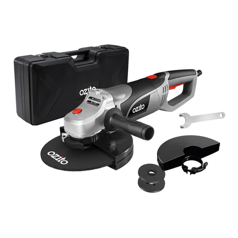
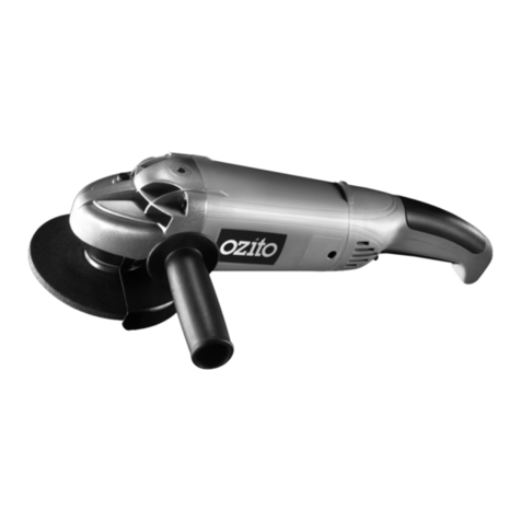
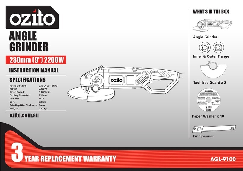
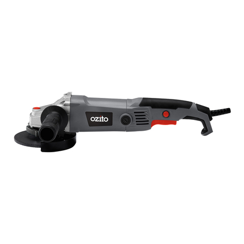
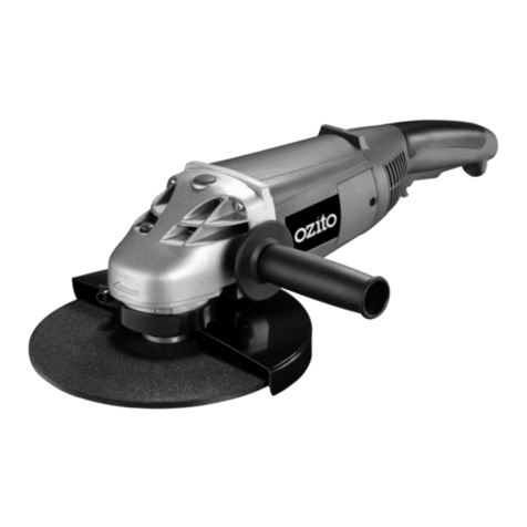
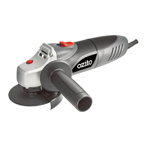
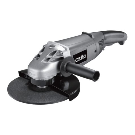
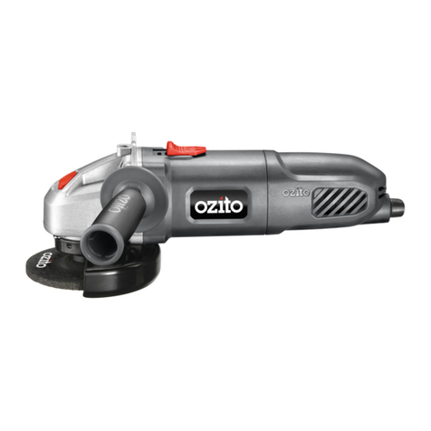
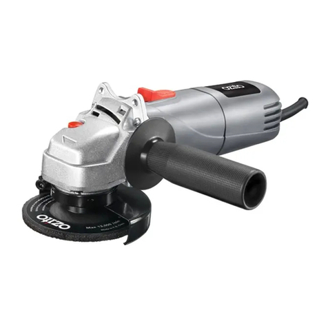
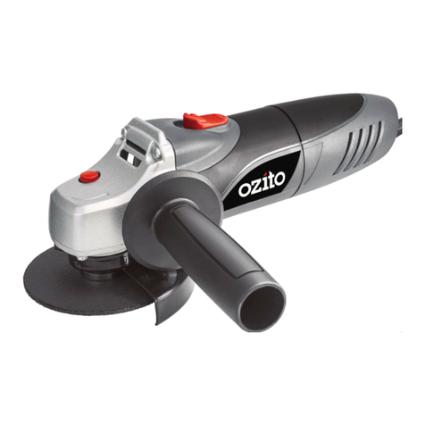
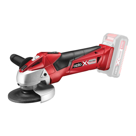
The side handle should be assembled to the grinder prior to use. This is done by
screwing the threaded end of the handle firmly in to the metal gear case of the
grinder. There are three different positions the handle can be fitted to the grinder.
Choose the most appropriate position considering user comfort and the task at hand.
Adjusting the Safety Guard
Ensure the guard is fitted and at an angle which ensures it is between you and the
disc/wheel. The guard is there to protect you from dislodging objects at the work
piece and from accidental contact with the disc/wheel, of your hand, fingers or
other parts of your body. To adjust the guard, loosen the guard securing screw
using a screwdriver. Rotate the guard into the required position, then refasten the
screw. Ensure the guard is firmly secured prior to use.
Attaching and Removing Grinding Discs
•Inspect the grinding disc before fitting and during use to ensure it is not
deformed or cracked.
Note: Always ensure replacement discs/wheels maximum no load “RPM” speed
exceeds the no load speed marked on the rating label of this grinder. Use of a disc
or wheel which maximum no load “RPM” speed is less than the grinders is a hazard.
• Remove the outer threaded flange by hand if loose. If tight, depress the spindle
lock button at the top of the metal gear case and rotate the spindle to locate
the lock position. With the spindle locked and the spindle lock button still
depressed, use the pin spanner supplied to loosen the outer retaining flange
(threaded flange).
• Holding the angle grinder with the spindle facing upwards, ensure the inner
retaining flange (non threaded flange) is on the spindle and located correctly.
The two machined flat sections on one side of the inner retaining flange must
face the angle grinder and locate in the appropriate position on the spindle.
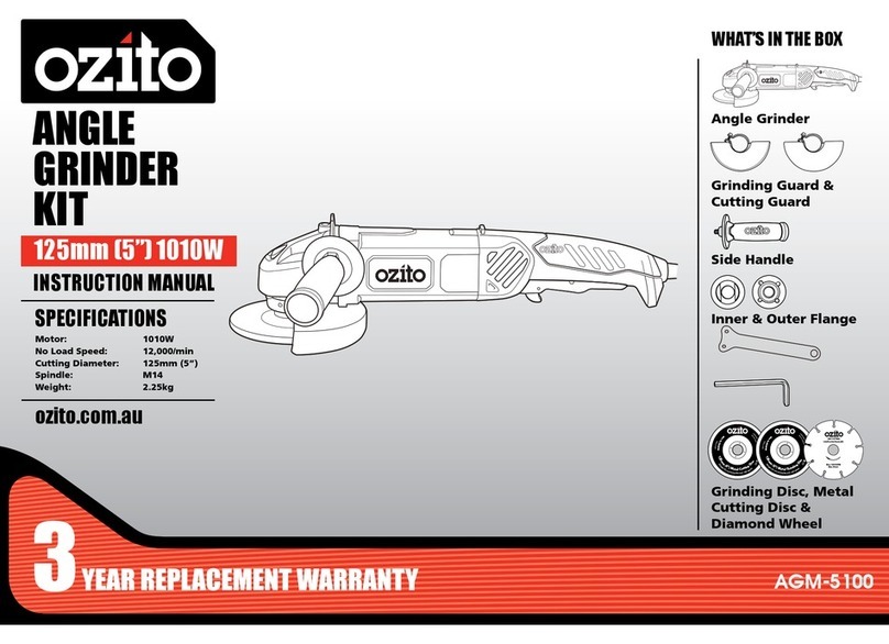
• Insert the grinding disc onto the angle grinder spindle with the disc label facing
the angle grinder. The hole in the disc should be located onto the spindle.
Ensure the hole in the disc locates and fits firmly into the ring section of the
inner retaining flange.
•Screw the outer retaining flange onto the spindle with the raised ring section
facing the angle grinder. This ring section must locate with in the hole in the disc.
•Tighten the outer retaining flange by locking the spindle as previously explained
then use the pin spanner to tighten the flange.
• Removal of the disc is conducted in reverse order to the above.
• Regularly check the disc retaining flange has not loosened during use.
Note: When fitting a cutting disc, the raised ring section on the outer retaining
flange should face away from the disc. The diamond cutting wheel should be fitted
the same as if fitting a cutting disc. The direction of the arrow on the wheel should
correspond with the arrow on the front of the metal gear case.
OPERATION (cont.)
8

