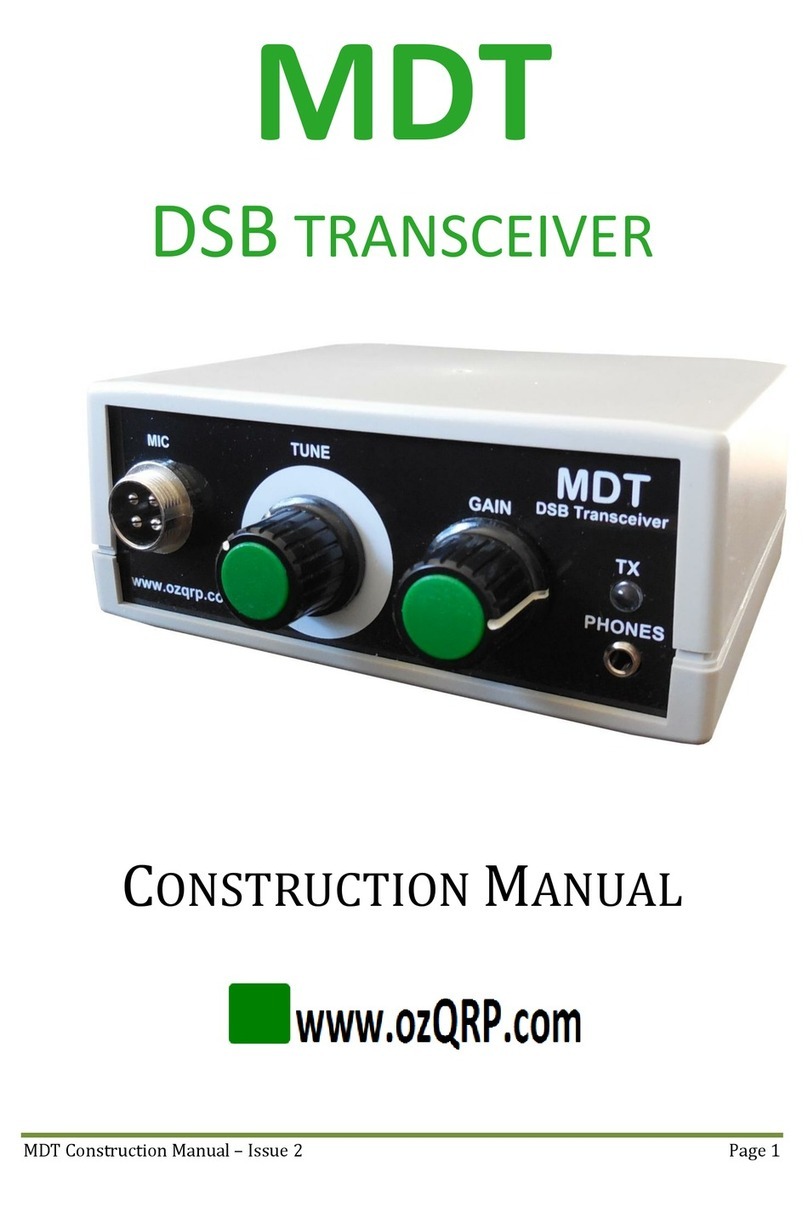
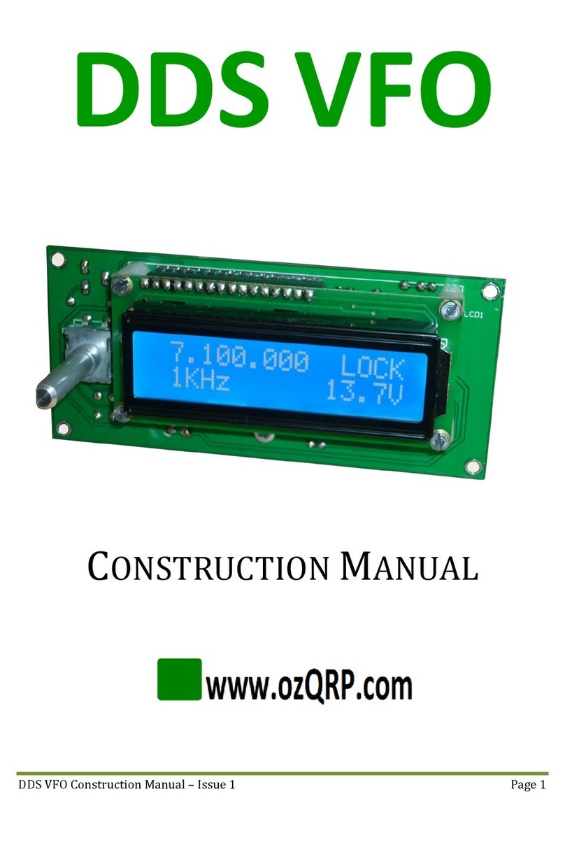
ozQRP MST3 User manual

MST3 Construction and Operation Manual –Issue 1 Page 1
MST3
SSB TRANSCEIVER BOARD KIT
CONSTRUCTION AND OPERATION
MANUAL

MST3 Construction and Operation Manual –Issue 1 Page 2
CONTENTS
1Introduction..............................................................................................................................................................5
2Block Diagram..........................................................................................................................................................7
3Circuit Description ................................................................................................................................................. 8
3.1 Carrier Oscillator ...............................................................................................................................................................8
3.2 SSB generator......................................................................................................................................................................8
3.3 Crystal Filter ........................................................................................................................................................................9
3.4 Transmit mixer ...................................................................................................................................................................9
3.5 Power amplifier..................................................................................................................................................................9
3.6 Power Supply and RX/TX switching ...................................................................................................................... 10
3.7 Receive mixer ................................................................................................................................................................... 10
3.8 Product Detector............................................................................................................................................................. 10
3.9 Audio Power Amplifier................................................................................................................................................. 11
3.10 Audio AGC .......................................................................................................................................................................... 11
3.11 Intelligent Tone Module .............................................................................................................................................. 12
3.11.1 Overview.................................................................................................................................................................. 12
3.11.2 Circuit operation .................................................................................................................................................. 12
4Kit Supplied Parts ................................................................................................................................................ 21
5Individual Parts List............................................................................................................................................ 23
6Off Board Parts...................................................................................................................................................... 26
7Main Board Construction.................................................................................................................................. 27
7.1 General ................................................................................................................................................................................ 27
7.2 Construction Steps ......................................................................................................................................................... 28
8Band Pass Filters.................................................................................................................................................. 38
8.1 Circuit description.......................................................................................................................................................... 38
8.2 Construction...................................................................................................................................................................... 39
9Low Pass Filter...................................................................................................................................................... 42
9.1 Circuit description.......................................................................................................................................................... 42
9.2 Construction...................................................................................................................................................................... 42
10 Adding a VFO ......................................................................................................................................................... 45
11 Enclosure................................................................................................................................................................. 46
11.1 Front Panel ........................................................................................................................................................................ 46
11.2 Rear Panel .......................................................................................................................................................................... 46
11.3 Mounting the PCB........................................................................................................................................................... 47
12 Wiring up................................................................................................................................................................. 48
12.1 general................................................................................................................................................................................. 48
12.2 Headers ............................................................................................................................................................................... 48

MST3 Construction and Operation Manual –Issue 1 Page 3
12.3 Power supply.................................................................................................................................................................... 48
12.4 Antenna............................................................................................................................................................................... 48
12.5 Key socket .......................................................................................................................................................................... 48
12.6 switches .............................................................................................................................................................................. 48
12.7 VFO........................................................................................................................................................................................ 48
13 Testing and alignment ....................................................................................................................................... 50
13.1 General ................................................................................................................................................................................ 50
13.2 Power on............................................................................................................................................................................. 50
13.3 Receive ................................................................................................................................................................................ 51
13.3.1 Carrier Balance ..................................................................................................................................................... 51
13.3.2 Receive BPF ............................................................................................................................................................ 51
13.4 Transmit ............................................................................................................................................................................. 51
13.4.1 PA bias setup.......................................................................................................................................................... 51
13.4.2 Transmit BPF ......................................................................................................................................................... 52
13.5 Audio AGC adjustment ................................................................................................................................................. 54
13.6 Carrier frequency adjustment................................................................................................................................... 55
14 Operation................................................................................................................................................................. 57
14.1 Power On............................................................................................................................................................................ 57
14.2 Receive state..................................................................................................................................................................... 57
14.3 SSB Mode............................................................................................................................................................................ 58
14.3.1 Introduction ........................................................................................................................................................... 58
14.3.2 Operation................................................................................................................................................................. 58
14.4 CW Mode............................................................................................................................................................................. 59
14.4.1 Introduction ........................................................................................................................................................... 59
14.4.2 Operation................................................................................................................................................................. 59
14.5 Test Tones.......................................................................................................................................................................... 60
14.6 Entering a Callsign.......................................................................................................................................................... 60

MST3 Construction and Operation Manual –Issue 1 Page 4
List of Figures
Figure 1 MST3 Block diagram..................................................................................................................................... 7
Figure 2 Carrier oscillator.......................................................................................................................................... 14
Figure 3 Balanced Modulator................................................................................................................................... 15
Figure 4 Crystal Filter.................................................................................................................................................. 16
Figure 5 Transmit mixer............................................................................................................................................. 17
Figure 6 Power amplifier and RX/TX switching............................................................................................... 18
Figure 7 Receive mixer................................................................................................................................................ 19
Figure 8 Receive audio................................................................................................................................................ 20
Figure 9 Component overlay .................................................................................................................................... 37
Figure 10 BPF schematic............................................................................................................................................ 38
Figure 11 Completed BPF........................................................................................................................................... 38
Figure 12 BPF overlay ................................................................................................................................................. 40
Figure 13 LPF schematic ............................................................................................................................................ 42
Figure 14 LPF overlay.................................................................................................................................................. 43
Figure 15 Completed LPF........................................................................................................................................... 43
Figure 16 MST3 in an enclosure.............................................................................................................................. 46
Figure 17 MST3 board and rear panel.................................................................................................................. 47
Figure 18 Wiring diagram.......................................................................................................................................... 49
Figure 20 Carrier frequency and crystal filter relationship......................................................................... 56
List of Tables
Table 1 BPF components............................................................................................................................................ 41
Table 2 LPF components ............................................................................................................................................ 44
Table 3 VFO selection .................................................................................................................................................. 45
Table 4 Typical circuit voltages............................................................................................................................... 53

MST3 Construction and Operation Manual –Issue 1 Page 5
1INTRODUCTION
The MST3 (Minimalist Sideband Transceiver series 3) is the next stage in the evolution of the
MST mono-band transceiver board.
While maintaining the minimalist approach of simple design, easy to build yet with good
performance, the MST3 takes the concept further by adding new features and performance
enhancements. These include:
1. Plug-in band modules, so that a single MST3 can be converted to another band easily
and quickly.
2. Switch input to shift the carrier frequency for USB and LSB operation.
3. Power supply reverse voltage protection using an on-board power MOSFET.
4. A new Intelligent Tone Module (ITM) forms a central role in the MST3, generating
audible tones and controlling the TX/RX switching:
a. CW operation. A good quality 800Hz sinewave is injected into the microphone
circuit when the Morse key is pressed. Adjustable volume sidetone is also heard
in the speaker.
b. Test and alignment. Three tone sequences can be selected using the Tone
button. A Morse test message including a callsign, a stepped frequency sweep
and a continuous tone.
c. Operator feedback. Changing between CW and SSB states is announced with a
Morse code message.
d. MST3 ident. Pressing the Tone button while in SSB transmit state will generate a
‘MST3’ CW message to identify with other MST3 users.
e. Power on indication. Two short beeps are generated at each power up to
indicate the microcontroller has booted successfully.
f. Callsign store. This is transmitted in Morse code during the test tone sequence.
This is entered using a Morse key.
With the addition of a VFO, an enclosure and a hand full of parts you have a complete and
working SSB transceiver.
Full kits of parts for the MST3 transceiver board and plug-in band filter sets are available from
www.ozQRP.com.

MST3 Construction and Operation Manual –Issue 1 Page 6
MST3 transceiver board specifications:
1. Operate on 80M, 40M 20M and 17M via plug-in band modules.
2. Switch selectable USB or LSB.
3. CW operation by keyed tone method. Tone frequency approximately 800Hz.
4. Sensitive Superhet receiver using a 5 pole 10MHz crystal filter. Sensitivity less than 1uV
for 10dB S/S+N.
5. Rugged power MOSFET output stage. Typical PEP/CW output power: 80M 7W, 40M 6W,
20M 5W and 17M 4W output.
6. TDA7052A speaker amplifier can deliver 1W into 8 ohms.
7. Audio derived AGC circuit to even out received audio level. Adjusted to cut in above
received signal level of S9.
8. Unwanted sideband suppression typically 40dB.
9. All harmonic and spurious transmit outputs below -46dBc.
10. Receive current drain approximately 90mA with no signal (excludes VFO).
11. Transmit current approximately 1A at 5W output.
12. Onboard MOSFET reverse polarity protection.
13. Microphone amplifier accepts standard low impedance dynamic or Electret microphone
with selectable on-board bias resistor.
14. Microphone sensitivity 20mV for full output.
15. Easily interfaces to any external VFO which can supply a signal level between 300mV
and 600mV pk-pk. Sideband selection and transmit mode control signals for intelligent
VFO controllers.
16. AF and microphone gain controls.
17. Connectors for optional LED S meter or a simple front panel LED transmit power and
modulation indicator.
18. PCB size 165mm x 110mm. Mounting holes 157mm x 83mm.
19. High quality double sided PCB with groundplane, solder mask and silk screen.

MST3 Construction and Operation Manual –Issue 1 Page 7
2BLOCK DIAGRAM
Figure 1 MST3 Block diagram

MST3 Construction and Operation Manual –Issue 1 Page 8
3CIRCUIT DESCRIPTION
3.1 CARRIER OSCILLATOR
Transistor Q2 is configured as a Colpitts oscillator and acts as the 10MHz carrier oscillator in
transmit and beat frequency oscillator (BFO) in receive. The frequency is determined by crystal
X1 and inductor L1 in conjunction with trimmer capacitors TC1 and TC2. When transistor Q1 is
turned off only TC2 is in circuit and this is adjusted to set the upper frequency of the oscillator.
When transistor Q1 is turned on by applying 12V to the U/L connector, TC1 is connected in
parallel with TC2. TC1 is then adjusted to set the lower frequency. Note that the trimmers are
not labeled USB and LSB because this depends on whether the VFO is above or below the IF
frequency.
The power supply to the oscillator is regulated with an 8V regulator REG1.
The oscillator feeds buffer stage Q3 via a small capacitor to provide minimal loading on the
oscillator. The buffer stage gives a low impedance drive for the balanced modulator. A lower
level output of around 500mV pk-pk is obtained at the junction of Q2 emitter resistors to feed
the receive product detector.
3.2 SSB GENERATOR
Transistor Q4 is the microphone pre-amplifier with a 20K ohm input impedance and gain of
around 10. C9 is included to prevent RF feeding into the amplifier. The output of Q4 is fed to the
Mic gain control via C15.
If an Electret microphone is used, R8 provides a DC bias current and is enabled by shorting LK1.
If a dynamic microphone is used LK1 is left open. Transistor Q5 is the second microphone
amplifier and has a gain of about 10. It is biased for higher current and has a low value collector
resistor to enable it to drive the balanced modulator. R16 and C19 form a low pass filter to keep
RF out of the amplifier.
The balanced modulator is a diode switching type and doubly balanced. The carrier signal,
which is much larger in amplitude than the audio signal, is applied simultaneously to both sides
of the mixer through trimpot VR1. The carrier signal alternately turns on the diode pairs to give
a low resistance and is why it is referred to as a switching mixer. As the carrier is capacitively
coupled it swings both positive and negative around ground potential. When the carrier is
positive, current flows through diodes D1 and D4 causing them to conduct and become a low
resistance. When the carrier signal goes negative diodes D2 and D3 conduct. Note that capacitor
C25 holds the junction of D1 and D2 at ground for RF. As the currents are equal through each of
the conducting diodes the differential voltage across the primary winding of T1 does not change
and as a result no RF is present at the secondary winding. If an audio signal is injected into the
bridge at the junction of D1 and D2 the mixer balance is upset because the audio changes state
much less frequently than the carrier signal and the resultant instantaneous diode currents are
not equal. As a result a signal is now output on the secondary of T1, which is a double sideband
suppressed carrier waveform.

MST3 Construction and Operation Manual –Issue 1 Page 9
Due to variations in component parameters the mixer balance is not exact and if not
compensated for the carrier balance would be poor. Trimmer capacitor TC3 and capacitor C26
are used to equalize the capacitance on the mixer sides, while trimpot VR1 is used to balance the
diode currents in each side. They are adjusted together to bring the modulator into balance. In
practice up to 50dB of carrier suppression can be achieved.
Diode D5 is used as an RF switch. With no DC current flowing through the diode it is high
impedance to RF. In TX state around 6mA of DC current flows through D5 and it becomes a low
impedance path for RF. This feeds the output of the balanced modulator into the crystal filter. In
receive D8 performs a similar function.
3.3 CRYSTAL FILTER
The crystal filter is a 10MHz 5 pole ladder type using closely matched crystals on the same
frequency. Capacitors C28 to C33 are selected to provide an approximate 2.7KHz bandwidth.
Resistors R26 and R27 terminate the crystal filter in the correct resistance to give low ripple in
the pass band.
3.4 TRANSMIT MIXER
The transmit mixer is based around U6 a SA612 balanced mixer. The 10MHz LSB signal from the
crystal filter is fed single ended into pin 1 while the other input on pin 2 is grounded to RF by
C59. The VFO signal of 300 to 600mV pk-pk is fed into pin 6. Transistors Q10 and Q11 act as
emitter follower buffers providing a balanced low impedance feed for the transmit band pass
filter. The output of the transmit band pass filter is capacitively coupled to the pre-driver built
around transistor Q11 which has both series and shunt feedback. The collector load is a
broadband transformer (T3) with a 10 to 3 turn ratio. R52 determines the DC collector current,
while R53 and C66 set the AC gain.
3.5 POWER AMPLIFIER
Transmit signal from the pre-driver is applied to the driver stage built around transistor Q13.
The circuit is identical to the pre-driver except for the use of a BD139 transistor and a larger
quiescent current of around 60mA. This is necessary to give linear operation with the larger
output power. The design is well proven using both shunt and series feedback to provide low
input and output impedance and good stable gain on the HF bands. The collector load is a
broadband transformer (T4) with a 10 to 3 turn ratio.
The power amplifier (Q14) is an IRF510 MOSFET and has been used in many designs. It is a
good candidate for the HF bands and can provide in excess of 5 Watts PEP from a 13.8 V drain
supply. The output from the driver is applied across resistor R60 and becomes the AC drive
component for Q14 gate. Zener diode ZD4 and trimpot VR3 provides a stable and variable DC
gate voltage to place Q14 just into conduction for linear service. There is a short ramp up of the
gate voltage when switching to TX state as capacitor C71 charges and is included to provide a
smooth gate voltage transition.
The drain load for Q14 is a broadband bi-filar wound transformer (T5) and was found to
provide maximum output into a 50 ohm load. The waveform from Q14 can be high in harmonics
and so a 7 pole low pass filter is included to reduce the level of harmonic and other spurious
energy to an acceptable level.

MST3 Construction and Operation Manual –Issue 1 Page 10
As a visual indication of power output and modulation, the transmit signal is sampled by
capacitor C77 and ground referenced by R65. The signal is rectified by D10 and filtered by C78.
This drives transistor buffer Q17 to drive an external LED S meter or a front panel LED via
current limiting resistor R67.
3.6 POWER SUPPLY AND RX/TXSWITCHING
When the PTT line is active, transistor Q15 is turned on by the ITM and operates the TX/RX
relay. When operated the transmit signal is passed to the antenna. When the PTT is not
operated the relay switches the antenna through to the receive circuits. The relay also switches
power to the TX and RX sections as required.
The power supply is also made available on separate connectors for the external VFO and LED S
meter.
A ‘P’channel power FET (Q18) protects the components in case the power supply is connected
in reverse. It works like this. For a P channel MOSFET to be turned on the gate must be at least
4V negative with respect to the source. The internal structure of a MOSFET has a diode
connected between the drain and source terminals and is reverse biased in its usual
application. However in this circuit if power is applied with the correct polarity, the internal
diode will be biased on and the source voltage will be around a volt below the drain voltage.
The gate is effectively at ground potential because of the 10K resistor and so the gate voltage is
more than 4V negative with respect to the source. This turns on the MOSFET and the drain to
source becomes a very low resistance, bypassing the diode, and supplying power to the board.
If the power supply is connected with reverse polarity the internal MOSFET diode will not
conduct. As a result the gate to source voltage never exceeds -4V and the MOSFET remains off
protecting the board.
Zener diode ZD5 protects the gate from over voltage spikes.
3.7 RECEIVE MIXER
Signals from the antenna are applied to the receive bandpass filter. The antenna is unbalanced
and capacitively coupled while the output is a balanced winding that feeds the mixer.
The mixer U2 is another SA612. The input is protected with a pair of back to back diodes and fed
differentially into pins 1 and 2. Zener diode ZD1 provides a stabilized 6.8 volt supply. VFO signal
is injected into pin 6 at about 300 to 600mV pk-pk. The balanced output which contains the sum
signal of 10MHz is fed to broadband transformer T2. The output of T2 is passed to the crystal
filter when DC current flows through R29 and into D8.
3.8 PRODUCT DETECTOR
The 10MHz SSB intermediate frequency (IF) signal from the crystal filter is applied to the
product detector U3. The product detector is formed with another SA612 and mixes the IF
signal with the 10MHz BFO signal to produce an audio output. The BFO is adjusted slightly
above the crystal filter response for LSB and slightly below the crystal filter response for USB
detection.

MST3 Construction and Operation Manual –Issue 1 Page 11
A balanced input audio amplifier is formed with one half of a NE5532dual low noise op-amp
(U4a). A reference supply for the non-inverting input is obtained from R31, R32 and C42. The
high frequency response of U4a is limited by C41, C45 and C47, while capacitors C43 and C44
reduce the low frequency response.
The output of U4a is fed via a 1uF coupling capacitor to the AF gain potentiometer. The audio
signal is also made available via R40 on a separate connector for a LED S meter to display
receive signal strength. Transistor Q7 is turned on in TX state and shorts the audio signal input
to the LED S meter to ground. This stops switching transients from being displayed.
As the receiver gain is fixed between the antenna and the AF gain control, the audio level across
the AF gain control is directly proportional to the receive signal strength. This allows an
optional LED S meter to measure this audio level and accurately display the receive signal
strength on an LED bar graph.
3.9 AUDIO POWER AMPLIFIER
Audio fed from the wiper of the AF gain control is amplified by the other half of the dual op-amp
(U4b) which is configured for a gain of 5. The amplified signal is then applied to the audio power
amplifier (U5) to drive a loudspeaker. This is a TDA7052A device with a Bridge-Tied Load (BTL)
output. This configuration has a number of advantages for operation at low supply voltages, and
also allows the speaker to be directly connected to the chip without the need for a large
coupling capacitor.
Both speaker wires are connected directly to the IC. Connecting a speaker wire or
external load to ground may damage the IC.
3.10 AUDIO AGC
The main reason for choosing the TDA7052A is the ability to alter the gain over a very large
range by varying the DC voltage at pin 4. If pin 4 is left floating an internal source provides
about 1.1V resulting in a maximum gain of +30dB. As pin 4 is pulled low the gain decreases, and
if pulled all the way to ground the device is effectively shut off. By varying the amount of current
pulled from pin 4 the gain can be continuously varied. This feature is used here to provide an
Automatic Gain Control (AGC) circuit to even out receive audio and limit blasts from the speaker
on very strong signals.
The power supply for U5 is set to +8V by a 7808 regulator. This is done for two reasons. Firstly
the TDA7502A can become unstable at high supply voltages, but more importantly to fix the
voltage at the output pins under no signal conditions. With no signal this voltage is half the
supply voltage (+4V), but when audio is fed to the speaker the voltage at pin 5 will swing above
and below the 4V quiescent point. The base of transistor Q9 is DC connected to pin 5 by a
resistor and a trimpot. The trimpot (VR3) is adjusted so that transistor Q9 is just below
conduction when there is no audio. When a signal is received the positive audio peaks at pin 5
will start to turn on Q9 and cause some current to be pulled from pin 4 and lower the gain.
When the audio decreases, Q9 will begin to turn off which raises the voltage on pin 4, and
increases the gain. This action continually attempts to adjust the audio level and provide AGC
action. Capacitor C56 stores the charge in between positive cycles to avoid Q9 turning off during
negative peaks and causing distortion. For such a simple circuit the dynamics are very good and
make a great addition to the receiver.

MST3 Construction and Operation Manual –Issue 1 Page 12
Transistor Q8 is controlled by the ITM to mute the audio amplifier as required. When Q8 is
turned on it pulls pin 4 immediately to ground and effectively shuts off U4 and prevents any
audio being heard in the speaker. When Q8 is turned off audio is passed to the speaker. This is
the normal case for receive state, but also to allow tones to be heard during transmission.
Whenever Q8 is turned off, capacitor C56 charges slowly and provides a smooth click-less
transition.
3.11 INTELLIGENT TONE MODULE
3.11.1 OVERVIEW
The Intelligent Tone Module (ITM) is based around an ATtiny85 microcontroller incorporating
a high speed pulse width modulation (PWM) generator. The ITM has a central role in the MST3
and performs the following functions:
Tone generator for CW operation. The keyed tone bursts are shaped to minimise keying
clicks.
Generate a range of test tones.
Send a MST3 ident during voice operation.
Generate user feedback for controls and functions.
Processing of Push To Talk (PTT), CW key closures and Tone pushbutton contacts.
Control of PTT and audio mute signals.
Entry and storage of a call sign.
3.11.2 CIRCUIT OPERATION
The ITM (U1) is clocked by an internal 8MHz oscillator. There is also an internal PLL circuit that
is used along with a divider to generate a 16MHz clock for the PWM module. When an audio
signal is generated the PWM is continually updated from a 256 value sinewave lookup table.
This equates to a sampling frequency of 62.5KHz. The highest required output frequency is
3KHz, and with such a high sample frequency this is easily obtained with a simple RC low pass
filter formed by R20 and C22. There is some remnant 62.5KHz ripple but this is inaudible in the
receiver and transmitted signal.
The PWM output (pin 6) is driven high and low when generating a tone. When the tone is
turned off the firmware forces the pin into a high impedance state, and the 10K resistors hold
the pin voltage at 2.5V. This means the tone waveform always starts and finishes at 2.5V and
minimizes DC transients that would otherwise cause audible clicks in the tones.
To further minimize the possibility of keying clicks the firmware shapes the start and finish of a
burst of tone by increasing the amplitude at the start of the waveform from zero to maximum
over about a 5mS period. This is done in reverse at the end of the tone burst.
The tones are coupled to the top of the Mic gain control via R14 and C14. The level of tone and
hence the transmitter output can be varied by adjusting the Mic gain control.
Internal tones are supplied to the audio amp via VR2 and C52. During transmit the ITM turns on
Q6 taking one leg of VR2 to ground. This now allows VR2 to adjust the level of sidetone during
transmit.

MST3 Construction and Operation Manual –Issue 1 Page 13
The ITM firmware continuously monitors the PTT switch, Morse key and Tone pushbutton. The
inputs are held high by internal pull-up resistors and filtered against RF with 1nF capacitors.
The Morse key and PTT switch are wired in parallel but are interpreted differently depending
on whether it is in SSB or CW mode.
The ITM also controls the audio mute line and the PTT line. In normal default SSB mode, the PTT
switch is passed straight to the PTT line.
At power up the ITM emits two short beeps to signal a successful boot up.
The ITM is supplied with +5V by a 78L05 regulator.

MST3 Construction and Operation Manual –Issue 1 Page 14
Figure 2 Carrier oscillator

MST3 Construction and Operation Manual –Issue 1 Page 15
Figure 3 Balanced Modulator

MST3 Construction and Operation Manual –Issue 1 Page 16
Figure 4 Crystal Filter

MST3 Construction and Operation Manual –Issue 1 Page 17
Figure 5 Transmit mixer

MST3 Construction and Operation Manual –Issue 1 Page 18
Figure 6 Power amplifier and RX/TX switching

MST3 Construction and Operation Manual –Issue 1 Page 19
Figure 7 Receive mixer

MST3 Construction and Operation Manual –Issue 1 Page 20
Figure 8 Receive audio
Table of contents
Other ozQRP Transceiver manuals