6
3 PRECAUTIONARY MEASURES AND
SAFETY INSTRUCTIONS
WARNING
• Always adhere to the local and national building and
electrical codes when installing or using the luminaire.
• Turn off and lock out the branch circuit before
commencing installation or maintenance work.
• Luminaires must be mounted min. 5" from walls and/
or other flammable materials.
• Do not open or disassemble the luminaire, it
contains no serviceable parts inside. Opening
the luminaire can be dangerous and will void the
warranty.
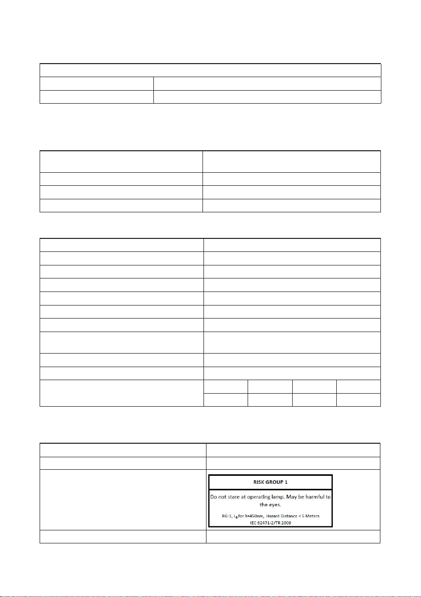
• Never look directly into the light source when
luminaire is turned on. Doing so can cause damage
to the eyes.
ATTENTION
• The end user is responsible for ensuring correct
installation and use of the product. Incorrect
installation can cause damage or defects to the
product.The warranty shall become void if the
product and/or electronic components are damaged
due to incorrect installation.
• The performance of the luminaire may be
compromised if operated outside of the
recommended ambient temperature guidelines.
4 INSTALLATION
4.1 PREPARATIONS FOR INSTALLATION
1Turn off and lock out the branch circuit..
2Refer to your light plan for specified mounting
locations.
3Remove the luminaire from the packaging and
check the contents (see section 2.2).
WARNING
Set the luminaire down with the glass lens facing
down on a cushioned surface to prevent damage.
4Gather any additional tools and/or hardware that
may be required to mount the luminaire.
If using mounting hardware other than the
original brackets supplied with the luminaire,
hardware must be able to support ≥60 lbs (27.2
kg) and be suitable for the surface(s) it is applied
to. Mounting solution must be approved during
inspection by local authorities having jurisdiction.
4.2 INSTALLING THE LUMINAIRE
STEP 1: MOUNT LUMINAIRE
The luminaire can be mounted to the supporting
structure in multiple ways, the most common options
are shown below:
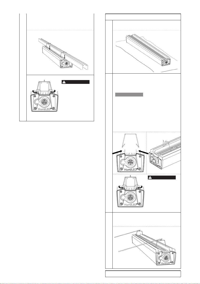
OPTION A: Standard Track/Truss Mount
1With one person supporting the luminaire on
either end, raise the luminaire so that it sits
flush beneath the track/truss.
2Lower one of the supplied mounting brackets
over the top of the track/truss at either end
of the luminaire. Insert the open ends of the
bracket into the mounting channel.
ATTENTION
Ensure that the two ends of the wire bracket
are facing toward the center of the luminaire
(away from the connectors on the ends), this
will allow for easier removal of the brackets if
the luminaire needs to be moved. If the brackets
are installed with the ends facing the connectors,
a screwdriver will be required to remove them
which could chip the paint on the luminaire.
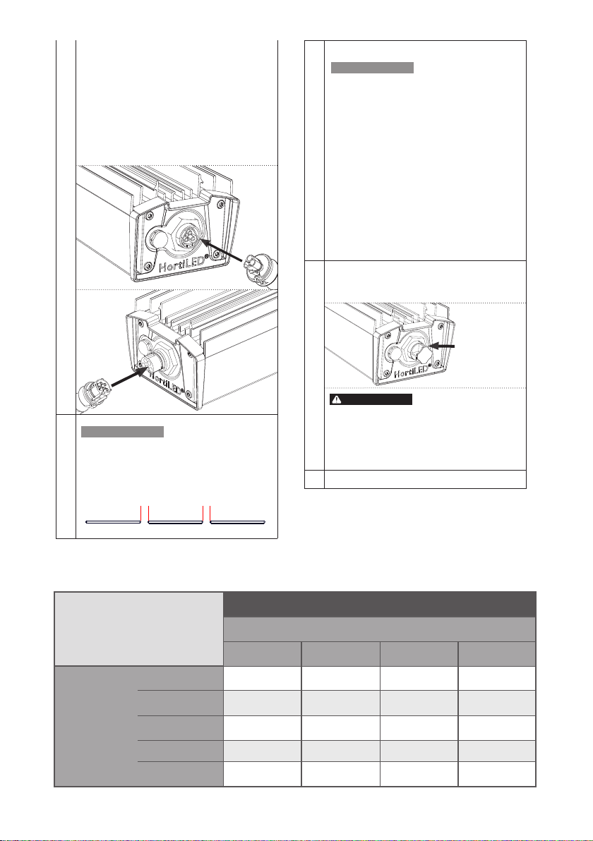
continues on next page...
ATTENTION
Check the dimensions
of your track/truss to
ensure proper fit with
supplied wire mounting
brackets.
WARNING
x
yz
w
w1.771 in (45mm)
x2.165 in (55mm)
y1.181 in (30mm)
z1.771 in (45mm)