P.L.LIGHT SYSTEMS HORTILED Top Operating manual

HORTILED®Top
EN User and installation manual


3
MANUAL FOR END USER AND
IN STALLE R
Thank you for purchasing the HortiLED®Top. This
manual contains all the information needed to quickly
familiarize yourself with the product. Please review this
information carefully, before installing and/or operating
the product.
We recommend you keep this manual on hand for
future reference.
For further information please contact:
P.L. Light Systems
4800 Hinan Drive
Beamsville, ON
Canada, L0R 1B1
T: 905.563.4133 / 1.800.263.0213 (toll free)
E: info@pllight.com
www.pllight.com
TABLE OF CONTENTS
1 Introduction 3
1.1 Product description 3
1.2 Symbols used 3
2 Technical specifications 3
2.1 General product specifications 4
2.2 Main components 5
2.3 Product dimensions 5
3 Precautions and safety instructions 6
4 Installation 6
4.1 Preparations for installation 6
4.2 Installing the fixture 6
5 Initial starting 8
Maintenance, environment and disposal
6.1 Repairing or shortening a cable 9
7 Troubleshooting 10
1 INTRODUCTION
1.1 PRODUCT DESCRIPTION
Intended use
The HortiLED®Top is a fixture intended for
overhead illumination of horticultural crops. For other
applications in professional horticulture, please contact
P.L. Light Systems.
Any use other than the approved intended use
described above is considered unintended use.
P.L. Light Systems cannot be held responsible for
possible consequential damage caused by improper,
incorrect or inadvisable use.
The HortiLED Top is referred to as the "fixture" in this
manual. The fixture is available in a number of versions
which vary in terms of distribution pattern, colour
spectrum and dimmability. This manual includes all
versions of the fixture.
1.2 SYMBOLS USED
The following symbols are used in this manual to draw
attention to specific topics or actions.
WARNING A warning indicates the
possibility of injury to the user
and/or damage to the product
should the user not perform
the procedures as described.
ATTENTION! A note with additional
information for the user.
A note alerts the user to
potential problems which may
occur if a procedure is not
carried out as described.
This is the UL certified logo,
which indicates that the
product meets UL’s stringent
standards for product safety
within the USA and Canada.
The WEEE logo indicates
that this product cannot be
discarded or disposed of
together with household
waste.

4
2 TECHNICAL SPECIFICATIONS
2.1 GENERAL PRODUCT SPECIFICATIONS
Product description
Name: HortiLED®Top
Market Introduction: 2016
TECHNICAL SPECIFICATIONS
Mechanical
Product Dimensions (L x W x H): 38.039 in. (966.2 mm) x 4.681 in. (118.9 mm)
x 3.740 in. (95.0 mm)
Product Weight: 18.08 lb. (8.20 kg)
Housing: Aluminum and glass
Ingress Protection Rating**: IP65
Electrical
Mains Voltage +/- 10% (see type sticker): 120 - 277 V AC, 50/60 Hz (grey connector)
347 - 480 V AC, 50/60 Hz (green connector)
Power Draw: Max. 320 W
Power Factor: > 0.95
Flux with R/B (LB): 860 μmol/s
Efficiency with R/B (LB): 2.7 μmol/J
Colour Spectra*: Red/Blue (low blue/medium blue/high blue)
Red/White (low blue/medium blue)
Full Spectrum
Custom*
Other
Ambient Operating Temperature: 0 ~ 30°C
Relative Air Humidity: 5% ~ 85% , non-condensing
Certification: UL Certified
Warranty: Visit www.pllight.com for warranty conditions.
* Can be tailored on a project-specific basis. Minimum quantities apply. **
Applies only with assembled connectors.

5
Light Distribution
The HortiLED Top is available in two distribution
options.
1An 80˚ distribution angle for effective penetration
of light into the crop.
2A 150˚ distribution angle for exceptional uniformity
of the light onto the crop.
80˚ distribution
150˚ distribution
2.2 MAIN COMPONENTS
2
5
3
4
1
2
5
3
4
46
1
Parts list
1Wieland Connector (Male)
2Glass Lens
3Housing
4Mounting Brackets (x2)
5GoreVent
6Wieland Connector (Female)
2.3 PRODUCT DIMENSIONS
38.039 in. (966.2 mm)
4.681 in.
(118.9 mm)
3.740 in.
(95.0 mm)
38.039 in. x 4.681 in. x 3.740 in.
(966.2 mm) x (118.9 mm) x (95.0 mm)

6
3 PRECAUTIONARY MEASURES AND
SAFETY INSTRUCTIONS
WARNING
•Always adhere to the local and national building and
electrical codes when installing or using the fixture.
•Switch off the mains voltage before commencing
installation or maintenance work.
•Do not open or disassemble the fixture, it contains
no serviceable parts inside. Opening the fixture can
be dangerous and will void the warranty.
•Never look directly into the light source whilst fixture
is turned on. Doing so can cause damage to the eyes.
ATTENTION
•The end user is responsible for ensuring correct
installation and use of the product. Incorrect
installation can cause damage or defects to the
product.The warranty shall become void if the
product and/or electronic components are damaged
due to incorrect installation.
•The performance of the fixture may be
compromised if operated outside of the
recommended ambient temperature guidelines.
4 INSTALLATION
4.1 PREPARATIONS FOR INSTALLATION
1Switch off the mains voltage.
2Refer to your light plan. Arrange boxed light
fixtures on floor in specified mounting locations.
3Remove the fixture from the packaging and check
the contents (see section 2.2).
WARNING
Set the fixture down with the glass lens facing
down on a cushioned surface to prevent damage.
4Gather any additional tools and/or hardware that
may be required to mount the fixture.
4.2 INSTALLING THE FIXTURE
STEP 1: MOUNT FIXTURE
The fixture can be mounted to the roof structure in
one of three possible ways:
OPTION A
1With one person supporting the fixture on
either end, raise the fixture so that it sits flush
beneath the track/truss.
2Lower one of the supplied mounting brackets
over the top of the track/truss at either end of
the fixture. Insert the open ends of the bracket
into the mounting channel.
3
While still supporting the fixture from below, push
down on brackets until they clip firmly in place.

7
OPTION B
1Place the fixture (with the glass lens facing down)
on a cushioned surface to prevent damage.
2Insert the open ends of the supplied mounting
brackets into the mounting channel on either end
of the fixture at a 45° angle, then tilt the brackets
upright until they clip firmly in place.
3
Raise the fixture and secure the attached
mounting brackets to previously installed side
brackets (not supplied) as shown below.
OPTION C
1Place the fixture (with the glass lens facing down)
on a cushioned surface to prevent damage.
2
Secure two M6 thread fasteners (not supplied)
directly to the roof structure in desired mounting
location.Thread an M6 hex nut (not supplied)
onto the end of each of the fasteners. Raise fixture
to ceiling and slide onto the fasteners, so that the
nuts sit securely on the inside of the channel, on
either end of the fixture (as shown below).
ATTENTION
Fasteners should be positioned approx. 5 in.
(12cm) from either end of the fixture when
mounted.

8
STEP 2: COMPLETE ELECTRICAL CONNECTION
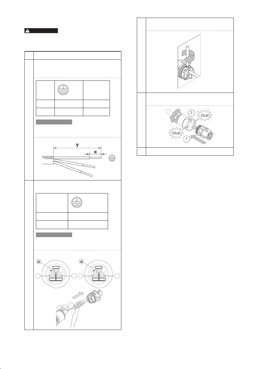
1Install female connector (supplied) to end of
power cable (refer to section 6.1)
2Once connection is complete, push the female
connector into the male connector on the end of
the fixture until firmly engaged.
WARNING
Ensure that the strain relief is properly fitted.
The contact can become damaged and water
ingress problems may arise if this is not the case.
3Switch on the mains voltage.
ATTENTION
In the event that multiple fixtures are mounted
consecutively, the distance between each
fixture must be a minimum of 4 in. (10 cm)
10 cm 10 cm
4 in
(10 cm)
4 in
(10 cm)
5 INITIAL STARTING
Switch on the mains voltage as a function test. See
Section 7 Troubleshooting if the fixture fails to light up.
6 MAINTENANCE, ENVIRONMENT
AND DISPOSAL
WARNING
• Switch off the mains voltage before commencing
maintenance work.
• Do not open or disassemble the product. Opening the
product can prove hazardous and will void the warranty.
ATTENTION!
In the event that the product is defective or damaged,
contact the dealer from whom you purchased the
fixtures, or PL Light Systems directly. Never switch on
a defective or damaged fixture.
• Check the product at regular intervals for build-up
of dust and dirt. Clean the product if necessary.
Contamination can lead to overheating and reduced
performance.
• Clean the fixture with a dry or slightly damp cloth.
Ensure that the glass lens (section 2.2, #2) is
always clean.
ATTENTION!
• Never clean the product with corrosive cleaning
agents, abrasives or other aggressive liquids.
• Protect the male end of the Wieland connector
(section 2.2, #1) against the ingress of water when
no female connector (section 2.2, #6) is attached.
• Only use a vinegar and water solution (1:100 ratio)
to remove build-up of limescale on the lens.
• In the event that the product is stored, it must be
kept in a dry, clean environment with an ambient
temperature of -20 ~ 50°C
• This symbol on the material, accessories
or packaging indicates that this product
may not be discarded as household waste.
Dispose of the equipment through a
recycling centre that handles electronics
and electrical appliances within Canada
and the United States of America which
use separate collection systems for used
electronics and electrical appliances.
By disposing of the equipment in the
proper way, you will be helping to prevent
possible risks to the environment and
public health, which might otherwise
be caused by improper handling of
the discarded equipment. Recycling of
materials contributes to the conservation
of natural resources.Therefore, please do
not dispose of your old electronics and
electrical appliances via household waste.

9
6.1 REPAIRING OR SHORTENING A CABLE
WARNING
The work in this manual should only be performed by a
qualified individual.
1Switch off the mains voltage.
2Push the wire through the first part of the female
connector and strip the wire to the correct
length:
N,L,
Y: 40 35
X: 8 8
ATTENTION
•The wire should have a diameter of 0.5 to
1.5 mm2.
3Push the wire into the correct connection.
Green/yellow
Blue N (L/N), L (L/L)
Brown L
ATTENTION
•In the event that a plug-in connector is used,
only use a wire with a hard core.
L
LN
N12
L2L1
Grey (120 - 277V) Green (240 - 480V)
4Secure the wire with the aid of a screwdriver,
if needed.
5Push the female connector together and
tighten the cable gland.
6Switch on the mains voltage.

10
7 TROUBLESHOOTING
WARNING
• Do not open or disassemble the product. Opening the product can prove hazardous and will void the warranty.
ATTENTION!
In the event that the product is defective or damaged, contact the dealer you purchased the fixtures from,
or PL Light Systems directly. Never switch on a defective or damaged fixture.
What can you see? What does it mean? What is the cause? What should I do?
The fixture does not
emit any light
• The fixture is
switched off
• No mains voltage
is present
• The fixture
temperature is too
high
• The mains voltage
is too high
• The mains voltage
is too low
Check the mains voltage and
ensure that it is within the
specified value range.
Reset the fixture by
disconnecting the mains
voltage from the fixture for
more than 5 seconds and then
reconnecting.
In the event that the fixture
switches off again, lower the
ambient temperature.
• Fault in one of
the fixtures
• Assembly fault Return the fixture for repair.
The fixture only half
lights up or flashes
Defect in the
electrical circuit
• Defective driver
• Defective circuit
board
Reset the fixture by
disconnecting the mains
voltage from the fixture for
more than 5 seconds and then
reconnecting.
If the problem persists, return
the fixture for repair.
The fixture emits
too little light when
compared to the other
fixture(s)
Defect in the
electrical circuit
• Fixture is defective Contact the installer and have
the wiring checked. If the
problem persists, return the
fixture for repair.
Dimmer activated Check the dimming
setting

11

© 2016 PL Light Systems HortiLEDTop User Guide 11.19
P.L. Light Systems
4800 Hinan Drive
Beamsville, Ontario
Canada, L0R 1B1
T: 905.563.4133 / 1.800.263.0213 (toll free)
www.pllight.com
Table of contents
Other P.L.LIGHT SYSTEMS Lighting Equipment manuals
Popular Lighting Equipment manuals by other brands

Bestway
Bestway 60302 manual

Elation
Elation PROTEUS SMARTY HYBRID WMG user manual

Goldine Controls
Goldine Controls Aqua Rite manual

Violet Defense
Violet Defense Vantage I User manual & warranty

Clevertronics
Clevertronics L10 LSBLED Series Installation & maintenance instructions

MaxLite
MaxLite HLRS Series operating instructions