www.p-light.com established 2000
Elektronics Maxi
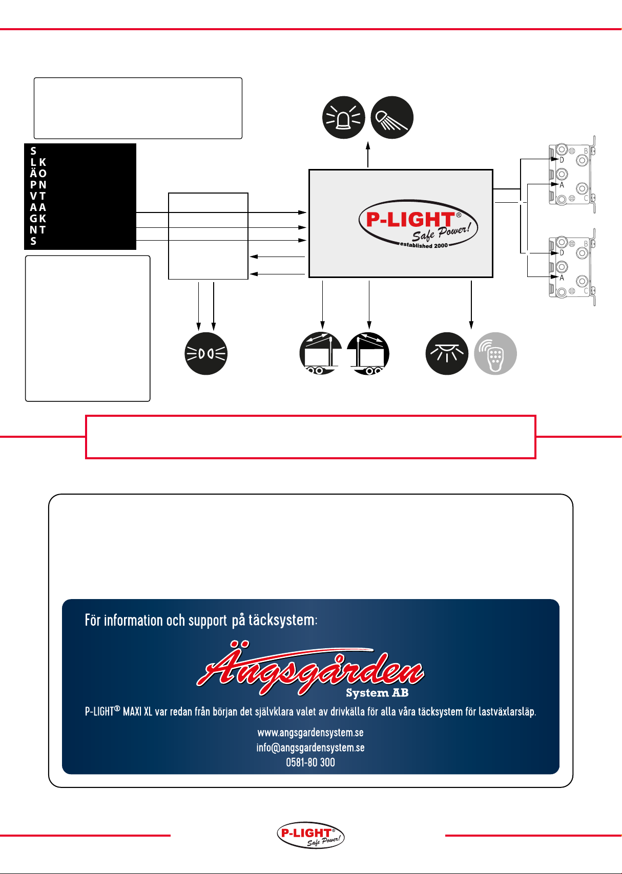
Elektronic terminals
Terminal no. Descripon
1. Baery+24V,connectedtoP-LIGHTbaery.
2. BaeryGnd(-),connectedtoP-LIGHTbaery.
3. Input Gnd (-) negave/ground, min 2.5 mm². From vehicle/
trailerhitch.
4. Input+24V“Lighngcircuit1”,min2.5mm².Fromthetrailer’s
hitch.
5. Output +24 V “Lighng circuit 1”, connected to parking and
sidelightswhicharetoremainonwhiledriving,andP-LIGHT
forshort-termparking.
NOTE:Mustnotbeconnectedtocablingconnectedtoterminal
4or6.
6. Input+24V“Lighngcircuit2”,min2.5mm².Fromthetrailer’s
hitch.
7. Output +24 V “Lighng circuit 2”, connected to parking and
sidelightswhicharetoremainonwhiledriving,andP-LIGHT
forshort-termparking.
NOTE:Mustnotbeconnectedtocablingconnectedtoterminal
4or6.
8. Input +24 V “Opon”. (Direct operaon to terminal 9, if, for
example, you connect the warning light to terminal 9, it’s
possible to connect the trailer’s reversing circuit here, this
acvatesthewarninglightwhenthevehiclereverses).
9. Output+24 V “Opon”e.g. warning light,worklighng,etc.
max.200W.Acvatedbypushbuon2.
10. Output +24 V “AUX”. Always +24 V even if the truck is not
connected,norcontrolledbyanypushbuon.Isintendedfor
operaonofe.g.externalradiocontrol,thecableisprepared
up to the rocker switch where you connect the required
equipment.Max200W.
21and22.Nofuncon.
23.Input+24Vfrompushbuon2“Opon”(acvatesterminal9).
24.Output+24Vtopushbuon2“Opon”(acvatesterminal9).
25.Input+24Vfrompushbuon1“Parking”(acvatesterminals5
and7).
26.Output+24Vtopushbuon1“Parking”(acvatesterminals
5and7).
Elektronik plintar
Plint nr. Beskrivning
1. Baery+24V,connectedtoP-LIGHTbaery.
2. BaeryGnd(-),connectedtoP-LIGHTbaery.
3. Input Gnd (-) negave/ground, min 2.5 mm². From vehicle/
trailerhitch.
4. Input+24V“Lighngcircuit1”,min2.5mm².Fromthetrailer’s
hitch.
5. Output +24 V “Lighng circuit 1”, connected to parking and
sidelightswhicharetoremainonwhiledriving,andP-LIGHT
forshort-termparking.
NOTE:Mustnotbeconnectedtocablingconnectedtoterminal
4or6.
6.Input+24V“Lighngcircuit2”,min2.5mm².Fromthetrailer’s
hitch.
7. Output +24 V “Lighng circuit 2”, connected to parking and
sidelightswhicharetoremainonwhiledriving,andP-LIGHT
forshort-termparking.
NOTE:Mustnotbeconnectedtocablingconnectedtoterminal
4or6.
8. Input +24 V “Opon”. (Direct operaon to terminal 9, if, for
example, you connect the warning light to terminal 9, it’s
possible to connect the trailer’s reversing circuit here, this
acvatesthewarninglightwhenthevehiclereverses).
9. Output+24 V “Opon”e.g. warning light,worklighng,etc.
max.200W.Acvatedbypushbuon2.
10.Output +24 V “AUX”. Always +24 V even if the truck is not
connected,norcontrolledbyanypushbuon.Isintendedfor
operaonofe.g.externalradiocontrol,thecableisprepared
up to the rocker switch where you connect the required
equipment.Max200W.Factoryconnectedtoterminal31.
21and22.Nofuncon.
23.Input+24Vfrompushbuon2“Opon”(acvatesterminal9).
24.Output+24Vtopushbuon2“Opon”(acvatesterminal9).
25.Input+24Vfrompushbuon1“Parking”(acvatesterminals
5and7).
26.Output+24Vtopushbuon1“Parking”(acvatesterminals
5and7).
30. Output +24 V to momentary rocker switch for control of
solenoidorrelay(factoryconnectedfromterminal31).
31.Output+24Vtotoggleswitchforexternalradiocontrol(factory
connectedfromterminal10).
32.Output+24Vtotoggleswitchtorelay(factoryconnectedfrom
31).
Note, terminals 30, 31 and 32 are monitored by voltage
monitors, and one of these must always be used for the
conneconofequipmentinordertopreventdeepdischargeof
baeriesandrisksofdamagetoconnectedequipmentdueto
excessivelylowvoltageduringoperaon.
34. Ground point power Gnd(-), cable dimension aer power
on (Cable to the negave terminal of the baery is factory
mounted).
41.Output+24Vpower(PTO),solenoid100Aorrelay50A.
42. Connected to terminal 43 (main power switch, factory
connected).
43.Connectedtoterminal42,(solenoidorrelay).
44.Cabletobaery’sposiveterminal(+)(factoryconnected).
F1.Powerfuse(PTO),solenoid100Aorrelay60A.Ifasmallfuseis
requiredadaptasrequired.
Elektronics Maxi XL STD
10