2 | Page
Table of Content
Opti Lite.................................................................................................................................................................. 1
INSTALLATION.................................................................................................................................................... 3
Input Wiring diagram.......................................................................................................................................... 4
Output modules................................................................................................................................................... 5
2x16A.............................................................................................................................................................. 5
2x16A in DCM mode...................................................................................................................................... 5
4x5A relays..................................................................................................................................................... 5
4x0-10V outputs.............................................................................................................................................. 5
4xPWM outputs .............................................................................................................................................. 6
2x16A Bi-stable relays.................................................................................................................................... 6
Motor controller.............................................................................................................................................. 6
The module has a built-in web server, for setup and control. ............................................................................. 6
Control page:....................................................................................................................................................... 7
System Page........................................................................................................................................................ 8
Configuration of the Output modules.............................................................................................................. 8
4xPWM........................................................................................................................................................... 8
System settings are straight forward. .............................................................................................................. 9
Trigger page...................................................................................................................................................... 10
Trigger settings: ............................................................................................................................................ 10
TECHNICAL SPECIFICATIONS ................................................................................................................... 10
OPTI Lite - Optimized for success
P5 Opti Lite has been developed with total flexibility and cost-effectiveness in
mind and will revolutionalize the way projects are managed.
The outputs of Opti Lite units are tailor-made. You no longer have to pay for
unused channels. Opti Light is the ultimate way to approach multi-dwelling unit
projects.
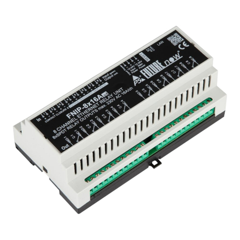
OPTI Lite is basically a 4in1 FutureNow (the established product range by P5)
with more power and resources. You no longer have to buy a different box for
each function. You can combine four different functions using a single box. For
example, you can use a single OPTI Lite unit to control a few on/off lights, RGB
LED lighting, blind control and even have digital inputs for sensors/manual
control or activating macros/scenes.


