p5 FutureNow FNIP-6x2AD User manual

2 | Page
Contents
MAIN FEATURES................................................................................................................................................. 3
INSTALLATION.................................................................................................................................................... 4
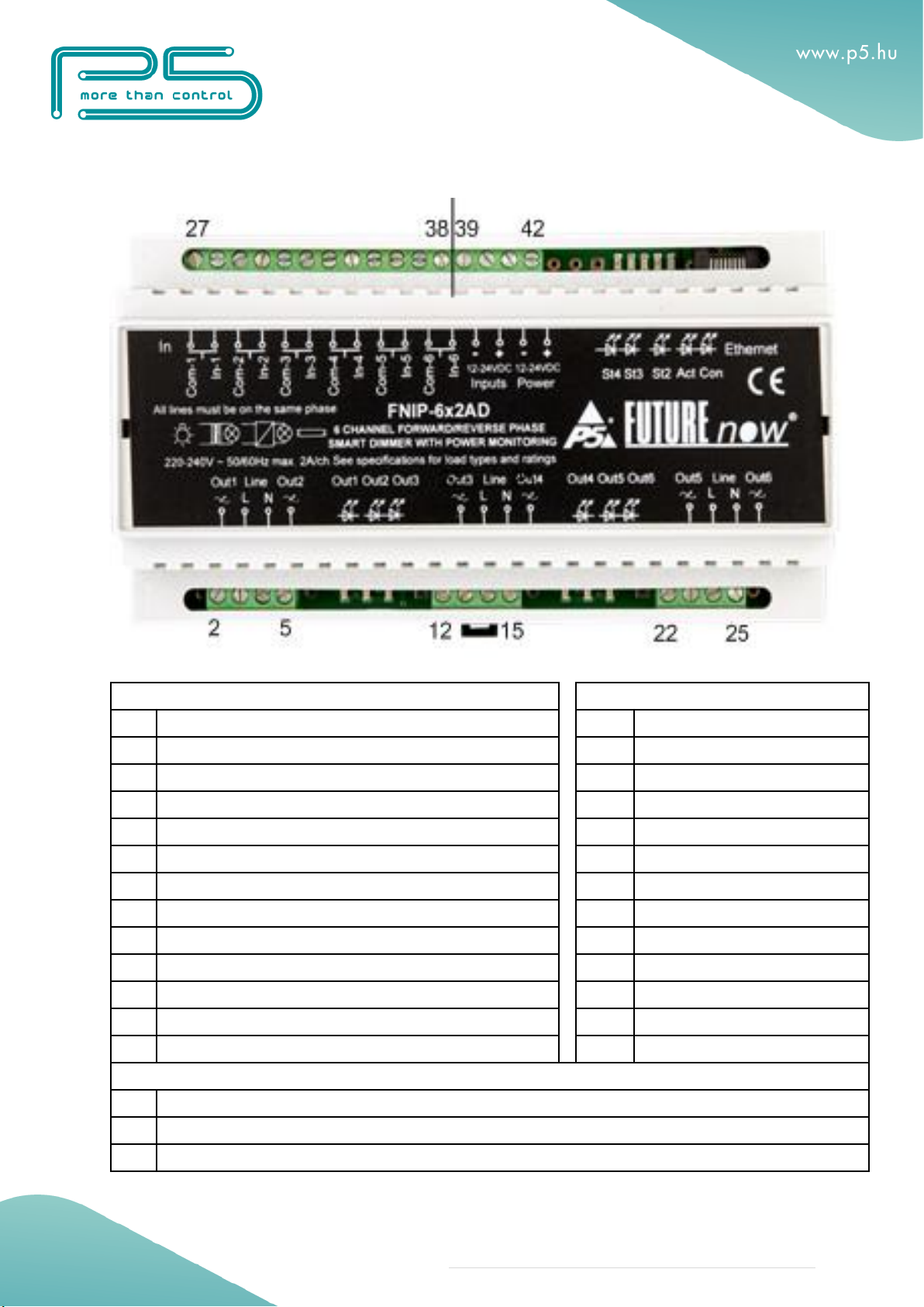
Terminal connections.......................................................................................................................................... 4
Wiring................................................................................................................................................................. 6
Outputs................................................................................................................................................................ 7
Local inputs......................................................................................................................................................... 8
Status LED indicators ..................................................................................................................................... 9
Input status LEDs............................................................................................................................................ 9
Run LED......................................................................................................................................................... 9
Input power LED ............................................................................................................................................ 9
Communication LEDs................................................................................................................................... 10
Output status LEDs ....................................................................................................................................... 10
CONFIGURATION.............................................................................................................................................. 11
Configuration via the web interface.................................................................................................................. 11
Connecting to the web server of the module................................................................................................. 11
Network settings ............................................................................................................................................... 12
Users and user rights......................................................................................................................................... 14
Channel settings................................................................................................................................................ 15
Dim settings ...................................................................................................................................................... 16
Combining channels...................................................................................................................................... 17
Scenes ............................................................................................................................................................... 18
Firmware Upgrade ............................................................................................................................................ 19
OPERATION........................................................................................................................................................ 20
Operation via local inputs ................................................................................................................................. 20
Input modes....................................................................................................................................................... 20
Operation via the built-in web server................................................................................................................ 22
Operation via TCP ............................................................................................................................................ 24
TECHNICAL SPECIFICATIONS ................................................................................................................... 25
REFERENCES.................................................................................................................................................. 26
CONTACT DETAILS...................................................................................................................................... 26

3 | Page
MAIN FEATURES
Fail-safe Operation
All-in-one dimmer
6 outputs for switching and dimming 6 lighting circuits
6 galvanically isolated multi-purpose inputs for direct control or connecting
digital sensors
Temperature monitoring
Overheat protection (both from software and hardware)
Overcurrent protection
Ultimate Flexibility
Switching on/off any loads (certain limitations apply)
Both trailing and leading-edge dimming
Automatic load type detection
Possibility to combine two outputs for more wattage
Standard DIN rail mount
Voltage, frequency, power consumption metering
100 dim levels (800 level hardware resolution)
Preset dim level –outputs will go to the specified level when turned on
Dim level memory (if preset dim level is set to zero)
Adjustable minimum and maximum dim levels
Adjustable ramp rates
Delayed off mode with adjustable duration
Lighting scenes
Enhanced Connectivity
Built-in web server for configuration, control and monitoring
Multiple users with different rights
TCP communication with simple ASCII commands
Automatic event reports of status changes of inputs and outputs
Firmware upgrade via LAN
Industry-Wide Interoperability
Full Integration with home controllers from most major vendors
Compatible with any momentary contact switches available on the market

4 | Page
INSTALLATION
WARNING! The module is connected to mains/line voltage! The
installation must be performed by a qualified electrician in
accordance with the local electrical codes!
Turn off power (main circuit breaker) before installation!
This equipment shall be installed in a closed cabinet with no access
to live parts. Only the top enclosure of the equipment (where the
label is affixed) is allowed to be accessed by the operator.
Terminal connections
Every FutureNow module has a wiring diagram on the front to help the installer
when connecting the modules at installation sites. See Figure 2.
The terminal connections of the FNIP-6x2AD are listed in Table 1.

5 | Page
Figure 2. FNIP-6x2AD front view with terminal connectors
Load
Control
No.
Description
No.
Description
2.
Output 1 Live
27.
Inputs Common
3.
230V Mains Input Live for ch1 and ch2
28.
Input 1
4.
Neutral INPUT
29.
Inputs Common
5.
Output 2 Live
30.
Input 2
12.
Output 3 Live
31.
Inputs Common
13.
230V Mains input Live for ch3 and ch4
32.
Input 3
14.
Neutral INPUT
33.
Inputs Common
15.
Output 4 Live
34.
Input 4
22.
Output 5 Live
35.
Inputs Common
23.
230V Main Input Live for ch5 and ch6
36.
Input 5
24.
Neutral INPUT
37.
Inputs Common
25.
Output 6 Live
38.
Input 6
Low voltage inputs for the module
No.
Description
39.
Power for the Inputs GND
40.
Power for the Inputs +10V.. +36V DC

6 | Page
41.
Power for the Main Circuit GND
42.
Power for the Main Circuit +10V.. +36V DC
Table 1: FNIP-6x2AD terminal connections
Wiring
A typical wiring diagram is shown in Figure 3.
Figure 3. Wiring diagram
All line inputs must be on the same phase and on the same circuit breaker!
Recommended wire types
Ethernet cable: Twisted pair, CAT5 or better.
Outputs: According to the loads attached to the outputs (current and voltage).
Inputs: A pair of low or high voltage cables. The inputs use low voltage signals.
Mains/line voltage wiring must be kept physically separated from Ethernet and signal
wiring.
Power requirements
The module requires 10V DC –36V DC through terminals 41 and 42.
N L N N
Light
1Light
2
N L N N
Light
3Light
4
N L N N
Light
5Light
6
Local inputs
+10V –36V DC for the inputs
+10V –36V DC for the main circuit
Ethernet
FNIP-6x2AD

7 | Page
If local inputs are to be used, 10V DC - 36V DC through terminals 39 - 40 is also
required.
Please make sure that the polarity is correct!
The galvanic isolation of the inputs is only effective when a separate power supply
is used for powering the inputs. The FNIP-6x2AD has separate power input
terminals (39 and 40) for this purpose. If you choose not to use the extra
protection the isolated inputs offer, you can use the same power to supply both
the main circuit and the inputs. In that case, simply connect terminal 39 to terminal
41 and terminal 40 to terminal 42.
Apply 230V 50 Hz AC live on terminals 3, 13 and 23 and neutral on terminal 4 and
14 and 24.
Please make sure that all the three line inputs (terminal 3, 13 and 23) are
on the same phase and on the same circuit breaker! Different phase
connection would create a short circuit and damage the module!
Live on terminal 3 powers output 1 and output 2, live on terminal 13 powers output
3 and output 4, live on terminal 23 powers output 5 and output 6.
The loads should be connected between the outputs of the module
(terminal 2, 5, 12, 15, 22, 25) and a neutral point somewhere outside the
module.
Connecting the Neutral legs of the loads to the module could damage the
module. This will void the warranty.
Ethernet connection
Connect the module to the LAN via the RJ45 Ethernet socket.
Outputs
The FNIP-6X2AD supports both trailing and leading edge dimming modes. It
handles most any lighting load be it resistive, inductive or capacitive, such as
incandescent, line voltage and low voltage halogens with both electronic and iron
core transformers, phase-cut dimmable fluorescents and compact fluorescents.
Phase-cut dimmable line voltage LEDs and LED Drivers must be controlled in
trailing edge dimming mode.

8 | Page
Do not attach any other type of load to the outputs if dimming of the
outputs is enabled! Using an improper load can damage both the attached
device and the FNIP-6x2AD, creating a potential fire hazard!
Only use lights with built-in ballasts/drivers that meet CE emission
standards. For example, spikes generated by certain LED drivers can
damage the dimmer.
Apart from dimming, the FNIP-6x2AD can also be used to switch (on/off only) non-
dimmable loads that don’t exceed the specifications.
As a precaution, dimming of the outputs is disabled by default. If you use dimmable
loads, you must enable dimming for each channel.
Local inputs
For each output there is a local input to allow for manual operation. If you do not
wish to use local inputs, this section may be skipped.
Connect dry contacts (pushbuttons, momentary switches, relay contacts, etc.) or
open collector transistor outputs across the appropriate input terminals and the
input common terminal. Voltage for the inputs is supplied by the module itself.
WARNING! Avoid supplying voltage on these terminals!
All input ports are galvanically isolated to protect the unit against unwanted effects
of ground loops, overvoltage or misconnections.
The galvanic isolation is only effective when an independent power supply is used
for powering the inputs. The FNIP-6x2AD has separate power input terminals for
this purpose. See section “Power Requirements” if you don’t want to use two
separate power supply units.
To assure an additional level of safe and reliable operation, the inputs are also
software protected against the effects of noise spikes that usually occur when
heavy inductive loads (motors, fans, etc.) are switched nearby.
Three-way switches can be implemented by simply connecting multiple
momentary switches in parallel.

9 | Page
Status LED indicators
In order to make installation and debugging easier, communication and channel
states are displayed via LEDs.
Use the board layout drawing in Figure 4. to locate the status LEDs.
Figure 4. The board layout of the FNIP-6x2AD
Input status LEDs
Each input has a dedicated status LED that illuminates solid green when the
corresponding input is activated.
Run LED
When on, it indicates that the Central Unit of the module works properly.
Input power LED
When illuminated, it indicates that the input power is present.
Er St
LEDs
Com
LEDs
Inputs 10V –36V Power Ethernet
Input Power
LED
Run LED
MCU
Output LEDs
1 2 3
Output 1
Output 2
Line in
Output LEDs
4 5 6
Reset
Input status
LEDs
Neutral
Output 3
Output 4
Line in
Neutral
Output 5
Output 6
Line in
Neutral
AC
2 6 12 15 22 25
27 38 39 42
-+
-+

10 | Page
Communication LEDs
Con LED
The Con LED is on when the module is connected to the Ethernet network.
Act LED
Indicates communication via Ethernet
Status LEDs
St LED
It is illuminated while the boot loader is active and it is blinking during a firmware
upload procedure. This should only happen during hardware resets and in the
second phase of firmware updates.
AC LED
Indicates the presence of the 50/60Hz line voltage
Er LED
The Er LED turns on if the module gets overheated. This LED will not turn off
until the module is power cycled or the temperature of the heat sink drops below
40°C.
Output status LEDs
Each output has a dedicated status LED that illuminates solid red when the
corresponding output is activated. In case of overcurrent the corresponding LED
starts flashing. The error condition resets when the output is turned on again.

11 | Page
CONFIGURATION
Configuration can be done either via the built-in website or via TCP/IP connection.
Configuration via the web interface
The FNIP-6x2AD automatically receives an IP address from a DHCP server.
In the lack of a DHCP server or when DHCP option is disabled on the network
configuration page of the module, the default IP address of 192.168.1.25 will be
assigned. The same IP address will be assigned when connecting the module
directly to your computer using an Ethernet cross cable (no DHCP server).
Use the FNIP Network Discovery Utility or other network discovery software to find
all FutureNow IP devices on your network.
Connecting to the web server of the module
Connect to the web interface of the module by using a web browser. Clicking on
one of the units found by the FNIP Network Discovery Tool will automatically do
that for you.
You can also access the web interface of the module via an internet browser using
the hostname of the module (FNIP-6x2AD by default) or its IP address. See the
list of supported browsers in the specifications below.
Once you are connected, you will be asked to identify yourself,
as seen in Figure 5.

12 | Page
Figure 5. Authentication window
Default user name: admin
Default password: futurenow
You will be logged in as an administrator with access to all settings and functions.
Once logged in, you will automatically be directed to the Control page. You can
use the tabs on the top of the screen to navigate between the different control and
configuration pages.
Network settings
To make basic network settings click the Network tab. The network configuration
page is shown in Figure 6.
You can choose between using DHCP or static IP address here.
Enable HTTP authentication
HTTP authentication can be disabled to make HTTP communication easier.
Enable broadcast messages
All FNIP modules periodically send out heartbeat broadcast messages with basic
information about themselves. This helps discovery tools and mobile apps to find
them. These broadcasts can be disabled if constant traffic on the network is a
problem.
Please note disabling broadcast messages will hinder the Discovery Tool and the
setup of the mobile applications.

14 | Page
Users and user rights
Three different users can be defined each with three different user rights: admin,
actor and observer.
Admins have access to all functions, including control of the outputs, monitoring
the status of the inputs and outputs and changing all the settings.
Actors are allowed to control the outputs and monitor the status of the inputs and
the outputs, but are not allowed to change any settings.
Observers are allowed to monitor the status of inputs and outputs but not allowed
to control the outputs, nor can they change any settings.
To change user settings, click on the User tab in the top menu. The user
configuration page is shown in Figure 7.
Figure 7. User configuration page

15 | Page
Channel settings
On the Channel page the outputs and inputs can be renamed. Input modes can
also be chosen here. The input mode determines the logical connection between
the input and the output of the same channel. For details on possible input modes
and how they work, see Operation via local inputs section of this document.
You can also choose the dimming method on the Channel page. As a general rule,
leading edge dimming can be used with resistive and inductive loads, while
capacitive loads require trailing edge dimming. If you are not sure which mode to
set, click on Detect and the module will automatically test the connected load type
and set the mode that suits best. For some loads you have to experiment to see
which mode works best. For example some phase-cut dimmable fluorescents and
LEDs work better with trailing edge dimming while others require leading edge
dimming. The channel settings page is shown in Figure 8.
Figure 8. Channel settings page

16 | Page
Dim settings
Preset level:
If other than zero, the output will go to the specified level when turned on. Zero
means the output will go to the last used dim level.
Minimum level:
Some load types cannot be dimmed down all the way to zero. They cut off at some
point and show some strange behavior (flickering or pulsing) below that dim level.
Light bulbs also need a minimum dim level to produce visible light. Setting the
minimum level slightly above these cut-off points makes these loads dimmable all
the way down more smoothly.
Maximum level:
The output will not go past this level. One reason may be to extend the lifespan of
the bulb or to limit the brightness to suit the environment.
Default ramp rate:
This is the time it takes for the light to go from zero to 100% when turned on/off
via the inputs, via the website, or TCP commands. Shorter ramps will take a
proportionally shorter time. For example, going from zero to 50% will take half the
time than what the ramp rate is set to.
Hold ramp rate:
The time it takes for the light to go from zero to 100% when the corresponding
input is held. Shorter ramps will take a proportionally shorter time. For example,
going from zero to 50% will take half the time than what the ramp rate is set to.
Dimming enabled:
There are loads that are not dimmable. Examples are most fluorescents and some
LED lights. These lights can only be turned on and off. Apart from dimming
dimmable lights, the FNIP-6x2AD can be used to only switch On/Off any types of
load that does not exceed the specifications. You can disable dimming by
unchecking the corresponding checkbox. Please note that dimming is disabled by
factory default.
Never enable dimming for non-dimmable loads. Doing so can damage the
device connected to the output, possibly creating a fire hazard!

17 | Page
Combining channels
If dimming or switching a higher load than what a single channel can handle is
required, it is possible to combine two outputs. Ch1 can be combined with Ch2,
Ch3 with Ch4 and Ch5 with Ch6. Outputs of a combined channels will always
produce the same dim level. There are two ways to combining channels.
Software only combination:
The channels can be combined by software only, by ticking the respective
checkboxes on the Dim Settings page. The combined pairs will be tied together,
they will always be at the same dim level but they are separate hardware outputs
with different loads connected to them.
Hardware and software combination:
Besides software combination, combined output pairs can also be combined by
hardware, by connecting them in parallel. They will then drive the same load. For
example, output 1 and output 2 can be connected in parallel.
The rating of the combined output pairs will be slightly lower than double the rating
of a single channel.
Connecting outputs that are not combined by software in parallel is
dangerous. It can damage the module, possibly creating a fire hazard!
Figure 9. Dim settings page

18 | Page
Scenes
Scenes are predefined states of the outputs on the module.
FNIP scenes can be used in standalone applications without any third-party
controller. FNIP modules (module groups) support 9 scenes.
If a module receives a Scene Activation Command (SAC), the designated outputs
will go to the defined state. Any module in the group can send and receive this
command. SAC can be triggered by an input change on this module, or on any
module in the group
Each module in the group must have the same Multicast address set on the
Network page. Modules in other groups will not receive the SAC.
Definition of the scenes happens on this page by the following
steps:
1. Select a scene
2. Define the action of the desired outputs.
3. Save the settings
4. Select another scene…
Figure 10. Scene setting page

19 | Page
Firmware Upgrade
Figure 11. Firmware upgrade page
Upgrading the firmware in the module is possible via the network.
On the Firmware page click browse and find the new firmware on your PC. The
latest firmware versions are always downloadable from the website of P5. Then
click Upload. The St LED turns on and stays on or blinks during firmware update.
After uploading the new firmware –which takes about a minute –the module will
automatically restart.
The version of the current firmware and the time since the last reset is also
displayed on this page.
Resetting to factory defaults
Holding the reset button for at least 2 sec while powering up the module will set
all the settings to factory defaults.

20 | Page
OPERATION
Operation via local inputs
The inputs can be activated by shorting or opening (depending on the settings of
the Channel Settings) an input terminal and the input common terminal.
Throughout this section it is assumed that momentary switches are connected to
the local inputs.
In order to use the local inputs, an input power of 10V - 36V DC must be applied
across terminals 39 and 41. If the inputs are not used, this power connection is
not necessary.
Input modes
The inputs are factory defaulted to toggle mode and can be changed via the web
interface of the dimmer or by TCP/IP commands. The input modes work as follows.
1. Toggle mode (factory default)
Each short button press toggles the corresponding output. Holding the button for
less than 0.5s will dim up and down (always in the opposite direction then last
time) the output until the button is let go of or the minimum or maximum dim
level is reached.
2. Independent inputs
Inputs can be detached from their corresponding outputs, in which case they will
have no effect on them. However, the status changes of the digital inputs will still
be reported via the open TCP/IP sockets and on the Control page of the built-in
website. This can be used for monitoring the status of digital sensors connected to
the inputs or to activate lighting scenes or macros whenever the input gets
triggered.
3. Input follow mode
The status the outputs will follow the state of the corresponding input. The output
will be on while the momentary switch is pressed and off while it is released.
Table of contents
Other p5 Dimmer manuals