Pace Edwards UltraGroove Electric KE2051 User manual

Tools Required for Assembly ......................................1
Before You Start ..........................................................1
Canister Drain Hole Locations ......................................1
STEP 1: Remove From Packaging, and
Review Contents ..........................................1
STEP 2: Install Wiring Harness ...................................2
STEP 3: Positioning Canister ......................................2
STEP 4: Installing Rails ...............................................3
STEP 5: Installing The Top Cover................................4
STEP 6: Installing The Clamp Extensions ...................5
STEP 7: Installing The Clamps ....................................6
STEP 8: Installing Tailgate Draintubes .......................8
STEP 9: Lubricating and Placing the Sweap Seals.......8
STEP 10: Connecting the Electronics ..........................8
STEP 11: Installing Canister Drain Tubes……………...9
STEP 12: Release Handle Instructions………………..10
Maintenance ……………………………………………..10
Release Handle Assembly Maintenance…...…………10
Warranty Statement…………………………………......11
KET1-1707
INSTALLATION INSTRUCTIONS
TOYOTA TUNDRA
TABLE OF CONTENTS
Electric Retractable Tonneau Covers
UltraGroove Electric
™
(800) 338-3697
www.paceedwards.com
Pace Edwards Company
2400 Commercial Blvd.
Centralia WA 98531

1
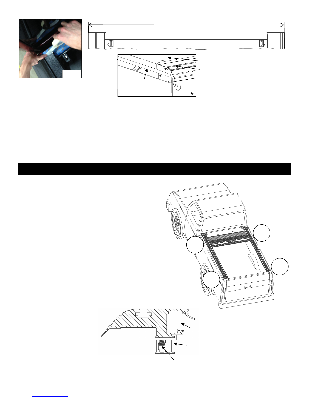
This tonneau cover is designed to carry rainwater
from the cover into the canister and then out
through the drains. Most truck models have
standard OE drain holes or plastic/rubber access
ports in the front of the truck bed. Check to make
sure your truck has the OE drain holes so that
drilling into the sheet metal is not required. If drilling
is necessary, be sure to check the underside of the
truck bed for the best location. The holes should be
located near the side and as far forward as
possible. Use a drill bit suitable for sheet metal
(such as a taper drill or step drill). Drill drain tube
clearance holes at 3/4” (19mm). This will need to be
done before installing the cover. (WARNING: Use
caution not to drill into wires, hoses or the cab!)
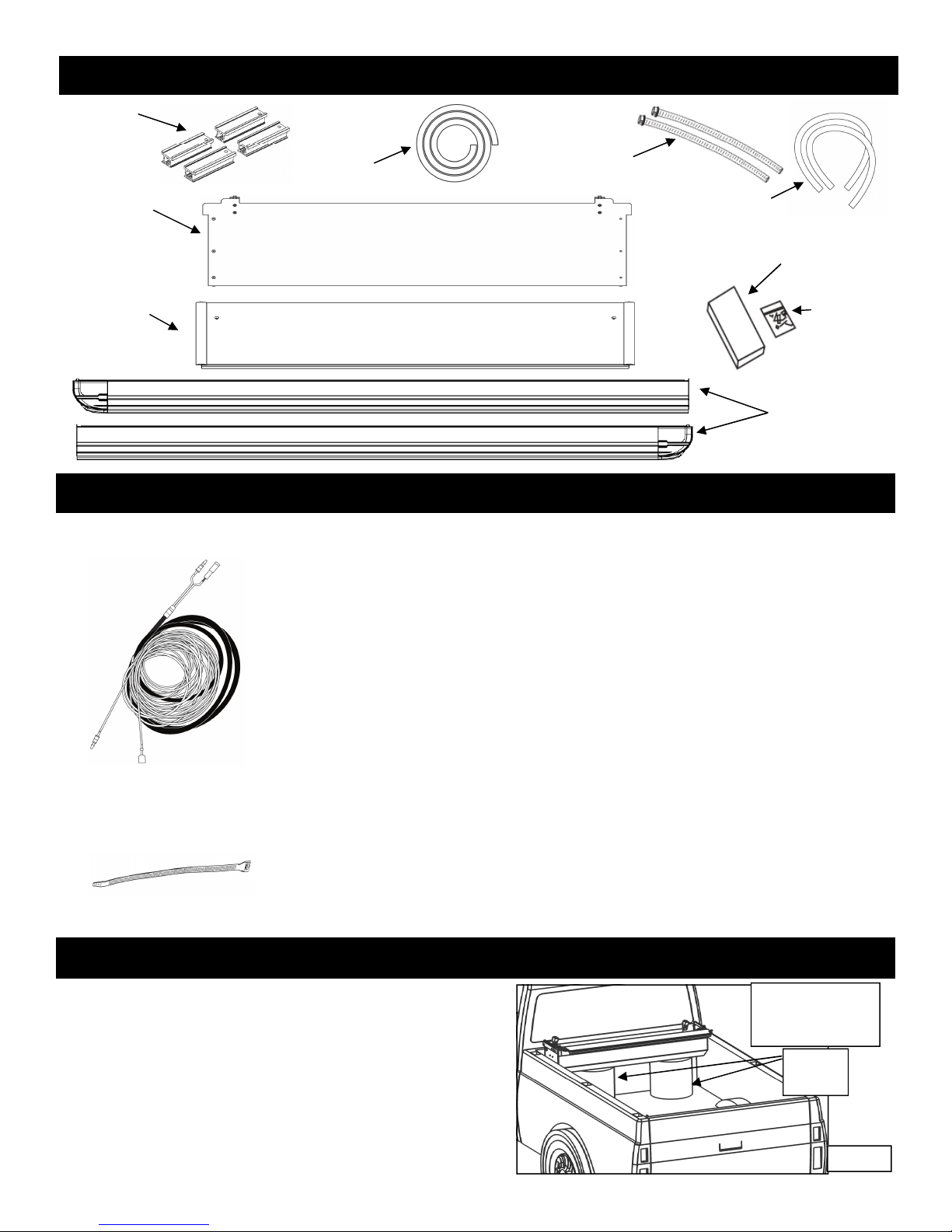
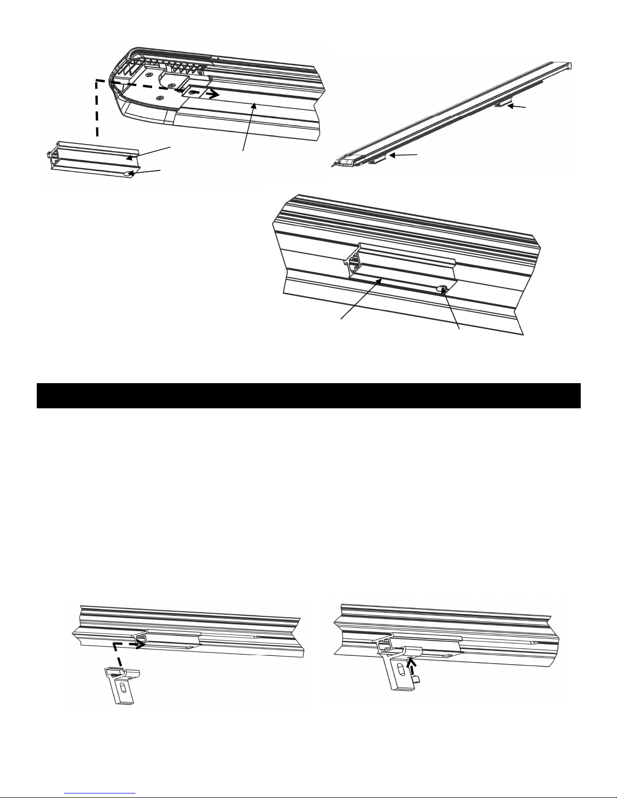
A complete unit will consist of one canister box (marked box 1 of 2) and one rail box (marked box
2 of 2). Remove the Top Cover, Canister, Clamp pack, Hardware pack, Foam, Clamp Extensions
and Drain Tubes from the Canister box. Remove the rails from the rail box (see caution below).
Perform a quick inventory of the packaging contents to ensure all parts are there. Using the 3/8”
wrench or socket, remove the 2 bolts holding the plywood packaging supports on the ends of the
canister. Discard plywood packaging supports and bolts.
TOOLS REQUIRED FOR ASSEMBLY
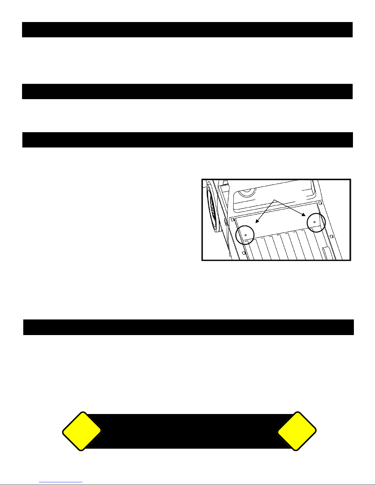
CANISTER DRAIN HOLE LOCATIONS:
STEP 1: REMOVE FROM PACKAGING AND REVIEW CONTENTS
Tape Measure Side Cut or Needle Nose Pliers Masking tape 3/8” Wrench
#2 Phillips Screwdriver Utility Knife 5/32” Allen Wrench
1/8” Allen Wrench
Note: There should be no drilling into the truck body needed on most standard or full-size trucks.
BEFORE YOU START!
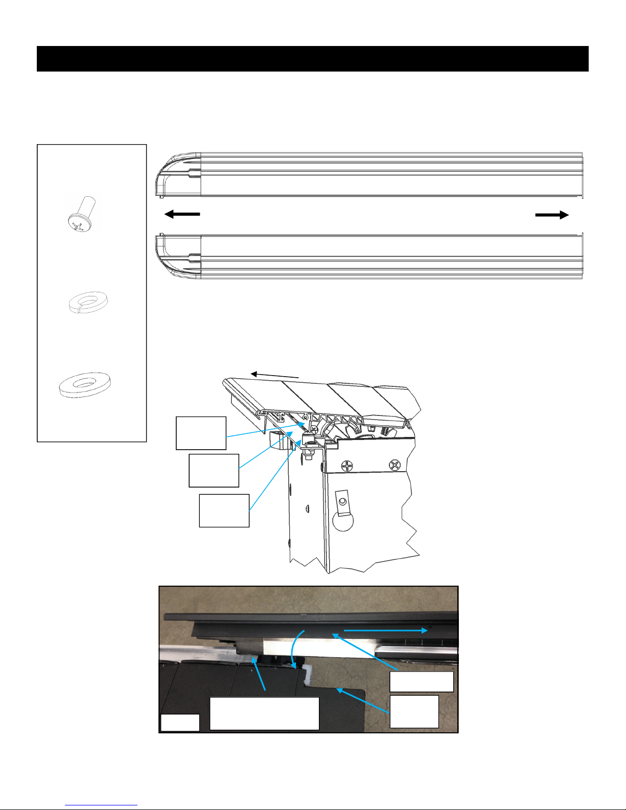
TO AVOID SCRATCHING THE SURFACE OF THE RAILS, DO NOT
SLIDE THEM OUT THE END OF THE BOX. OPEN THE BOX
ALONG THE LENGTH, USE PLIERS TO PULL THE STAPLES,
LIFT THE RAIL OUT. DO NOT USE A KNIFE TO CUT THE BOX
CAUTION! CAUTION!
Drain Tube Holes
Read the instructions carefully before you start. If you have any questions regarding the installation please
call our Technical Support Line at (866) 419-4932

2
Rails (Left and
Right) - In
separate box
than canister
STEP 2: INSTALL WIRING HARNESS
(If the optional wire harness Part# BL1120 is used, you may want to tape it to
the main harness to ease having to pull them through the bottom of bed
separately).
From inside the truck bed push the long wire harness end without the plug
through the stake pocket on the drivers side of the truck and out the underside
of the truck bed box.
Leave approximately one foot of slack inside the box for mounting the
electronics.
Route the wire harness under the truck and to the battery in the engine
compartment.
Attach the fuse holder to the end of the Red/positive wire.
(Do not attach to the battery yet.)
Secure the harness with wire ties provided after slack from the canister had
been taken out.
HARDWARE USED:
WIRE HARNESS x 1
ZIP TIES x 5
PACKAGING CONTENTS:
Complete
Canister
Assembly
Top Cover
Canister Drain
Tubes
Clamp Pack
Hardware
Pack
Top Cover
Foam
Tailgate Drain
Tubes
Place the Canister in truck bed just behind the cab and
center it from side to side. You will need to place the
canister on elevating objects, such as the box the
canister came in or 5 gallon buckets. (If you have
someone to help you, you can jump to step 5 and
install the assembled canister and rails on the truck.)
Note: Ensuring that the canister is centered in the bed
will help assemble the rails to canister in the next step.
STEP 3: POSITIONING CANISTER
FIG. 3B
Elevating
Objects
Canister needs to be
high enough to have
rail install clearance
Clamp
Extensions

3
STEP 4: INSTALLING RAILS
Left Rail
Right Rail
Tailgate End Cab End
Remove the protective paper from the foam on the underside of the Rail flanges. This is for
packaging purposes only.
Next identify the left and right side rails (FIG 4A). The rail flange and foam towards the outside of
the truck bed.
HARDWARE
USED
:
1/4-20 X 5/8” RAIL
SCREW x 2
1/4” FLAT
WASHER x 2
1/4” LOCK
WASHER x 2
First make sure that the Lead Rib Flange is in pulled toward the tailgate
enough to clear the Canister Flange and Canister Stop (FIG 4B).
Figure 4B shows that the
lead rib needs to be
pulled out toward the tail
gate. Now hook the rail
into the rail guide and roll
it down making sure to
not get the sweep seal
folded back into the rail
(FIG 4C &9A).
FIG. 4C
Hook Rail feature into
Rail Guide here
Sweep Seal
Lead Rib
Notch
FIG. 4B
Canister
Flange
Lead Rib
Flange
Canister
Stop
PULLOUT
FIG. 4A
FIG. 4B

4
STEP 5: INSTALLING THE TOP COVER
Remove the 303 protectant sponge that is adhered to the underside of the Topcover and set it aside for step 10.
Shut the tailgate and pull the rails back until the tailgate cap seals have good engagement with your tailgate. A good
way to check for proper engagement is to make sure the bottom cap and tailgate have 1/4” gap (FIG 5A).
FIG. 5A
BLACK TOP COVER
SCREW x 2
6FT OF FOAM
INSTALLATION
TOOL x 1 FIG. 5C
Another way to set the tailgate cap seals is to use the Tailgate
Seal Gauge as shown in figure 5B & 5C. You should be able to
just slide the Tailgate Seal Gauge in between the Tailgate Cap
Seal and the Bottom Cap.
WARNING: Proper Tailgate Cap Seal Engagement is
important for getting the best possible water resistance out
of your cover!
Tailgate
Bottom Cap
Tailgate
Cap Seal
BR Gauge
Tailgate Seal
Gauge
FIG. 5B
FIG. 4F
FIG. 4E
FIG. 4G
Rail Guide
Rail
Then you can thread the Lead Rib into the rail an push the rail forward to the end of the can (FIG 4E
&4F). If you have difficulty threading the Lead Rib into the rail, you can gently lift up on the lead rib with
your left hand while pushing the rail forward with your right. Next push the cab caps into the front of the
rails (FIG 4G). Finally secure the rail to the canister with the Rail Screws proved with flat washer and
lock washer (FIG 4H).
Lead Rib
threaded into
rail
Cab Cap
Left Rail Flat Washer
Lock
Washer
FIG. 4H
Rail Screw
FIG. 5A

5
STEP 6: INSTALLING THE CLAMP EXTENSIONS
Slide the clamp extensions on the tailgate and cab end of
each rail as pictured in Figure 6A-6E. Ensure that your
tailgate end and cab end extensions are in the correct
orientation and have the correct stick on shims. Each clamp
extension is labeled for front left (FL), front right (FR), back
left (BL), and back right (BR). The extensions go on the
corners shown in figure 6A.
Once you have the clamp extensions on the cab and
tailgate end of the rails as shown in Figure 5E and tighten
the set screws with a 5/32” Allen Wrench. If you have
trouble sliding on the clamp extension, make sure your
set screw is not sticking out the top of the clamp
extension.
BR
BL
FR
FL
FIG. 6A
Next mark where the front of the rails sit and mark this position with masking tape, this will be a guide for placing your
foam. (FIG 5D). Now pull the cover back until there is room to apply the foam. Lay the foam on the front sill of the truck
from rail to rail, trimming the excess with a utility knife (FIG 5E).
Now scoot the rails and canister back on the foam and double check that your tailgate seal engagement is good. You can
now install your top cover with the two included screws while making sure it aligns with the front of your rails (FIG 5F).
WARNING: Proper top cover foam installation is important for getting the best possible water resistance out of
your cover!
FIG. 5E
FIG. 5D
Foam
Rail
Top Cover
FIG. 5F
Clamp Extension
Rail
Set Screw
FIG. 6B

6
STEP 7: INSTALLING THE CLAMPS
Slide the Clamp Grip onto the Clamp Extension from the tailgate to the canister (Fig 7A). Next install the set screw to
lock the Clamp grip to the Clamp Extension with a 1/8” Allen Wrench (FIG 7B).Then assemble the rest of the clamp
parts as shown (Fig 7D or 7E). Be sure to the proper clamp combination for your truck. Figure 7D is the clamp
assembly for trucks without the Deck Rail System Track and Figure 7E is for trucks with the Deck Rail System Track.
Now tighten your clamp bolts with a 7/16” Nut Driver. DO NOT TIGHTEN OVER 120 INCH POUNDS!
Finally, check for proper spacing by measuring between the rails by attempting to insert the BR Gauge in between the
rail metal and the handle stop (Fig 7F). You can also check the between the rail measurement at the canister and the
tailgate end of the rails. The measurements should be equal to or less then those in Figure 7C. The Clamp Extensions
have been pre-installed with brackets and shims to achieve the proper Between the Rail dimension (BR) when placed
on an average factory truck bed. However, not all truck beds are average dimensionally and some have optional plastic
caps or over the rail spray-in liners.
FIG. 7A FIG. 7B
FIG. 6C
Rail
Set Screw Hole
TAILGATE END
Clamp Extension
FIG. 6D
Cab End
Location
Tailgate End
Location
When you slide your clamp
extensions to the desirable
tailgate and cab locations tighten
the set screw with a 5/32” allen
wrench
Set Screw Access
FIG. 6E

7
FIG. 7C
Part number is on
the serial number
label in the upper
left corner of the
canister (looking
from tailgate).
PART BETWEEN
NUMBER RAILS (BR)
KE2051 58 13/16
KE2052 58 13/16
KE2053 58 13/16
Rail
Handle
FIG. 7F
Pinch
Clamp
Flat Washer,
Lock Washer
Clamp Grip
Rail
FIG. 7D
No Track System Clamps
Outside of
Truck Bed
FIG. 7E
Track System Clamps
Clamp Grip
Flat Washer,
Lock Washer
Deck Rail
System Track
Track
Nut
Rail
Another way to ensure proper fit is to check the side to side play of the handle assembly at the
canister and at the tailgate end of the rails. There should be, at the minimum, enough play to
allow the cover to move freely with no drag and at a maximum 1/8 inch per side. More then 1/8
inch per side may result in the cover opening unintentionally and in severe cases it may fall
between the rail tracks and damage the cover. There are “Stick on Shims” in the hardware
pack that can be added if too loose.

8
Locate the sweep seals (rubber weather strips) on the rails.
Open the provided 303 brand protectant sponge pack that you
removed from the Topcover in step 5 (find it adhered to the
underside of the top cover). Wipe the underside of the sweep
seal and the top of the wear strip.
Extend the cover to the tailgate. Use an Allen wrench if
needed to carefully draw out the sweep seal (seal should be
angled outwards toward the cover – not rolled in toward the
bed rail). (Fig. 9A)
Proper care and placement of the sweep seal will ensure the
smooth operation of the cover. Alcohol, petroleum based or
silicon-based UV Protectants such as Armor-All® should be
avoided and ARE NOT recommended for our covers.
STEP 9: LUBRICATING & PLACING THE SWEEP SEALS
FIG. 9A
STEP 8: INSTALLING TAILGATE DRAINTUBES
To install the tailgate drain tubes you need to find suitable holes in the
rear stiffener of you truck bed. Figure 8C shows possible hole
locations.
Next you will screw the drain tube into the drain fitting and slide it on
the tailgate cap as shown in Figure 8B. There is an interference bump
on the cap that will lock the drain fitting in place. Next you will need to
thread the drain tube in the desired hole and trim the length of the
tube if needed. If there are no holes on the tailgate side of your truck
you will need to drill holes, make sure to check for wires you could
damage first (5/8” or 16mm).
WARNING: Drain tube installation is paramount to getting the
best possible water resistance out of your cover!
FIG. 8A
FIG. 8B
Tailgate Drain
Fitting
Tailgate Drain
Tube
Tailgate Cap
TAILGATE DRAIN
TUBES X 2
DRAIN FITTINGS
X 2
Possible Hole
Locations
FIG. 8C
STEP 10: CONNECTING THE ELECTRONICS
The electronics box has been pre-mounted to the inside of the canister.
Connect the battery wire harness into the 2-wire plug at the end of the canister (also connect the
optional manual switch harness, if installed at this time)
Attach the Red (positive) and Black (negative) wires to the battery or the truck manufacturers
suggested connection points at this time.
Unit is now ready to operate.
Press the Open button to open cover and press the Close button to shut the cover.
2-BUTTON REMOTE
KEY FOB x 2
HARDWARE
USED:
RIBBED BLANKET
SWEAP SEAL
RAIL
SOLID WEAR STRIP

9
First, ensure that the Foam Washer is in place on the Drain Fitting as this
washer will help prevent water leakage. Next, test fit the drain tube to
determine the length you want to trim it. Always caution on the long side. Trim
the end that will be inserted through the truck bed using the wire cutters or a
utility knife.
With the cover opened, insert the drain tube fittings into the pre-drilled holes
on the underside of the canister by pushing them in place from under the
canister. Drain Fitting should click into place.
Place the other end of the drain tube through the plastic/rubber access port or
through the pre-drilled holes in the floor or the front wall of the truck bed. If
routing through the front wall, ensure that the drain tubes are inserted and
directed down so water flows out of the truck. (WARNING: Use caution not to
drill into wires, hoses or the cab!)
To remove the drain tubes reach under the canister, grab the drain tube fitting
and turn it while applying light downward pressure. When the retaining tabs
align with notches in the bottom of the canister the Drain Tube and Fitting will
drop out.
STEP 11: INSTALLING CANISTER DRAIN TUBES
Notch
Feature
Foam
Washer
Drain Fitting
Drain
Tube
FIG. 11A

10
STEP 12: RELEASE HANDLE INSTRUCTIONS
If power is lost to the Ultragroove Electric unit or the electric drive system fails to operate and you have to use the
cover right away you can do the following to open or close the
cover:
1. You will need to gain access to the release handle located
on the driver side of the canister at the front of the truck
bed. Once you have access to it, Pull the handle out away
from the canister and pull out the handle kickstand behind
it.
2. Settle the kickstand into the notch on the handle to hold
the handle in place.
3. Now you should be able to push or pull the paneled
blanket manually open or closed.
NOTE: The blanket will not lock unless you disengage the
kickstand and lower the release handle. With the handle released the cover will move a short distance and the
cover will then lock itself in place. (Cover may not lock tightly against tailgate) This process will allow you to use
the cover until power is restored. It is not meant for extended or permanent use.
RELEASE HANDLE ASSEMBLY MAINTENANCE
Maintenance of the Release Handle Assembly requires lubrication of the coupler located inside the canister.
This is done during factory assembly but may need to be done from time to time during the life of your cover.
A small lubrication hole is provided on the coupler that a fine tipped grease gun can inject a small amount of
grease into. A high quality waterproof wheel bearing grease is recommended.
To get to the coupler you will need to remove the rail clamps and end caps at the end of the rails. Use the
manual release handle and manually pull the blanket out the end of the rails until you have access to the
coupler inside the canister. Grease the coupler, cycle and spin it to distribute lubricant then reverse the process
to re-assemble the cover being sure to manually push the cover back into place in the canister. (DO NOT USE
THE MOTOR TO RUN THE BLANKET INTO THE CANISTER OR YOU WILL DAMAGE THE RIB CAPS ON
THE EDGES OF THE BLANKET.)
MAINTENANCE
Drain Tube Fitting Retaining Tab
Foam Washer
Canister Drain Tube
FIG. 13A
After installation, if the cover is tight or hard to open and close,
the shimming may need to be re-adjusted.
Periodically remove the Top Cover and clean out the canister.
Drain tubes may become clogged overtime and should be
removed and cleaned. To remove the drain tubes reach under the
canister, grab the drain tube fitting and turn it while applying light
downward pressure. When the retaining tabs align with notches in
the bottom of the canister the Drain Tube and Fitting will drop out.
(FIG. 13A)
To help keep your Ultragroove Electric Retractable Tonneau Cover looking it’s best, we recommend washing it the
same way you wash your truck. However you should not wax your cover.
FIG. 12A

11
On your purchase of a UltraGroove
TM
Electric by Pace Edwards. We are confident that you will get many years of
trouble free service from this accessory on your truck. Please take a moment to fill out the warranty registration form to
activate warranty coverage of your truck bed cover.
PACE EDWARDS (hereinafter referred to as the MFG.) warrants
each new Pace Edwards UltraGroove
TM
retractable truck bed cover to
the original owner as follows:
FOR A PERIOD OF 3 YEARS FROM THE DATE THE UNIT IS
DELIVERED TO THE FIRST PURCHASER:
• Delamination of the Fabric Panel Assembly
• Failure of the Continuous Tension Spring
• All hardware and components
ITEMS NOT COVERED UNDER WARRANTY FOR ANY PERIOD
OF TIME:
• Rips, tears, or discoloration of the Fabric Panel material
• Seals and gaskets
• Water intrusion from any source
• Dealer and/or purchaser installed parts and accessories
CERTAIN CONDITIONS WILL VOID ALL WARRANTY.
These conditions include:
• Use for any purpose other than normal private use including
rental and promotion
• Altering the retractable truck bed cover in any manner without
written approval of the MFG
• Misuse, negligence or accident
• Installation of any part or accessory without written approval
from the MFG
• Failure to register this warranty with the MFG within fourteen
(14) days from date of delivery
CONGRATULATIONS!
CLAIMS:
If you have any warranty issues, please contact Pace Edwards Technical Support at (866) 419-4932 with the original Bill of Sale, the Unit Model and
Serial Number. After determining the validity of the warranty claim, Pace Edwards will ship a replacement part prepaid to the customer. Labor costs to
replace defective parts are the responsibility of the purchaser.
REGISTRATION:
Registering your UltraGroove
TM
Electric by Pace Edwards Retractable tonneau is an important step to ensuring you get the best possible ownership
experience. At the same time, we would like to better understand how your truck fits into your life. Your feedback from using the Ultragroove Electric
by Pace Edwards Retractable tonneau owners helps us design products that better fit your needs. REGISTER TODAY AT:
www.pace-edwards.com/Pace-Warranty
• Any part of a Pace Edwards UltraGroove
TM
Retractable tonneau that
is found to be defective under the terms of this warranty will be
repaired or replaced using either new or reconditioned parts at the
discretion of the MFG.
• In determining what constitutes a failure under the terms of this
warranty the decision of the MFG shall be final.
• This warranty is extended to the original purchaser only and is not
transferable to subsequent purchasers.
• The MFG does not accept any responsibility in connection with the
installation of any of its products by its dealers or agents.
• The MFG does not undertake responsibility to any purchaser for
warranty express or implied by any of its dealers, distributors or
agents beyond that which is contained herein.
• Without regard to an alleged defect of its products the MFG under
any circumstances does not assume responsibility for loss of time,
inconvenience, revenue, or other consequential damage including,
but not limited to, expenses for telephone, food, lodging, travel, loss
or damage to the vehicle the products are installed on or loss or
damage to personal property of the purchaser or user of the
products.
• The MFG reserves the right to make changes in the design of,
improvements to, or warranty of its products without imposing any
obligation upon itself to provide the same for any products
theretofore manufactured.
CONDITIONS AND LIMITATIONS
This warranty is subject to certain conditions and limitations including, but
not limited to, the following:
Some jurisdictions do not allow limitations on or exclusions to warranties,
therefore some of the exclusions may not apply to you. This warranty
affords you specific legal rights. You may have other legal rights that may
vary from jurisdiction to jurisdiction.
2400 Commercial Blvd, Centralia, WA 98531 USA Thank you for choosing products by…
(360) 736-9991
(main)
(360) 736-9992
(fax)
(800) 338-3697
(toll-free)
www.paceedwards.com
PACE EDWARDS PRODUCT WARRANTY
This manual suits for next models
8
Table of contents
Other Pace Edwards Automobile Accessories manuals
Popular Automobile Accessories manuals by other brands

Rival
Rival 2333.0334.1 installation manual

Active Controls
Active Controls ActiveStart ACS30P Installation, operation & application guide

Bundutec
Bundutec BUNDUCUBE owner's manual

DreamGEAR
DreamGEAR DGPSV-3301 user guide

EAL
EAL EUFAB BIKE THREE manual

Monster
Monster iCruze MPC FX IC-MB1 Installation & user guide