manuals.online logo
Brands
  1. Home
  2. •
  3. Brands
  4. •
  5. PACH & COMPANY
  6. •
  7. Control System
  8. •
  9. PACH & COMPANY AeGIS 7000 Series User manual

PACH & COMPANY AeGIS 7000 Series User manual

AeGIS 7000 SERIES
AeGIS 7000 SERIES
INSTALLATIONAND PROGRAMMING GUIDE
The installer must follow the installation requirements in the manual and quick
guide accurately. Failure to follow the installation requirements may void your
warranty. Read our warranty in the manual.
If this is the first time you are installing the AeGIS 7000 Series, we recommend
you read the complete Installation and Programming manual. The Quick guide
is written for someone who is already familiar with the AeGIS 7000 Series
installation and programming.
FOR MISSING PART(S)
DO NOT RETURN THE PRODUCT TO YOUR DISTRIBUTOR, CALL 1-888-
678-7224 AND ASK FOR TECHNICAL DEPARTMENT FOR REPLACEMENT
OF THE MISSING PART(S). YOU MUST PROVIDE THE SYSTEM SERIAL
NUMBER.
FOR DEFECTIVE SYSTEM
DO NOT SWAP THE BOARD FROM ANOTHER SYSTEM, THIS WILL VOID
YOUR WARRANTY.CALL 1-888-678-7224 AND ASK FOR TECHNICAL
DEPARTMENT FOR ADVANCED REPLACEMENT BOARD OR PART(S).
YOU MUST PROVIDE THE SYSTEM SERIAL NUMBER. THE SERIAL
NUMBER IS LOCATED ON THE BOARD.
Pach & Company 941 Calle Negocio Phone: 1-888-678-7224
www.pach-co.com San Clemente, CA 92673 Fax: 949-498-6879
L OG O NTO P R O G R A M M I N G M ODE
Press and simultaneously then release, the display screen will stop scrolling, then enter the 4-
digit Master Code (default is 0000), the screen will show
Select the FUNCTION CODE from the table below to continue programming. Note: if the display is still scrolling
after pressing 0 and # simultaneously, repeat the step above. If you do not know the MASTER CODE, see Fig. 1
to retrieve it. F U N C T I O N C O D E T A B L E
Exit the programming or clear the
existing field and reset the alphabet key stroke
if out of sequence. 10 CHANGE WELCOME SCREEN
Divided into 3-segments. Each segment consists
of 16 characters. Total is 48 characters long.
Accepting program or Entering into the function
code. 46 SYSTEM INFORMATION
Display the model number and firmware released
date.
00 REPLACE SYSTEM MASTER CODE
Default is 0000. Enter a new 4-digit Master
Code. 50 CLEARTHEMEMORY TO FACTORY DEFAULT
01
ADD NEW TENANT
Consists of directory code (unique number,
default 3-digit, see function code 06), name,
phone number and access code (4-digit).
70
CHANGE TALK TIME
010-180 seconds, default setting is 60 seconds.
02 EDIT EXISTING TENANT
You must know the directory code to edit, see
function code 78. 71 CHANGE DOOR OPEN INTERVAL
The length of time for the relay to trigger (ON).
04-99 seconds. Default setting is 12 seconds.
03 DELETE EXISTING TENANT
You must know the directory code to delete,
see function code 78. 72 CHANGE LOCKOUT COUNT
The system will be disabled for one minute if
invalid code has been entered.
04 CLEAR ALL TENANTS
This function code will clear the system tenants
database. 74 ENABLE OR DISABLE AUTO ANSWER
1= Enable (system will answer incoming call)
0=Disable (system will not answer incoming call)
05
MANUAL CLOSED OR OPEN THE DOOR BY
HOURLY TIMER.
01-98 hours to open the door, 99 hours to open
the door for indefinite time, 00 hours to closed.
75
TURN ON AND OFF KEY PRESS BEEP
1=ON (key will beep if press)
0=OFF(key will not beep if press)
06
DIRECTORY DIGIT
Select 2, 3, or 4-digit directory. Factory default
is 3-digit. 76
TURN ON AND OFF SPEAKER BEEP
1=ON (system will beep if door is open), default
setting
0=OFF (system will not beep if door is open)
07
SINGLEOR MULTI SYSTEMS
0= Single System ( more than one system on
the same phone line).
1 = Single System. Default setting.
78
VIEW DIRECTORY BY NAME
Use to find tenant directory. Press 3 (A-Z) or 6 (Z-
A) to scroll the press # to display directory code.
08
SYSTEM ID NUMBER
Select for 1-8. It is not necessary to select the
ID number if remote touch-tone programming is
not used.
To Enter Name: Press the correspondence key on the
keypad and follow by . Press
after entering the letter.
Select Func: _ _
To place a call from the system:Press 3 or 6 to scroll tenant name
A-Z or Z-A, then press # to call
To place a direct call from the system: Press # and wait for dial tone then
press the Directory Number associated with the tenant name.
To grand access to visitor: Tenant must press 9 from his or her phone.
To use the 4-digit access code to release the door:Press * (screen must stop
scrolling) then press the 4-digit access code.
To extend talk time: Tenant must press # after the time-out beep.
To call to the system and talk to the visitor (Function Code 74 must be
enabled):Dial the system phone number then you will hear “One short beep”
that means you are connected to the system, then press * on your phone to
communicate with your visitor. You may release the door for your visitor by press
9 on your phone.
Press for space between First name and Last name.
Press for back
“space.
Press to clear the field
or reset the letter key stroke if
out of sequence.
Figure 1
SYSTEM POWER
16-18 GAUGE 2-CONDUCTOR
STRANDED WIRE
12VAC40VA is supplied, input
voltage must be read 12.5-13.5VAC
with the system ON.
12VDC 3A is not supplied,input volt-
age must be read 13.5-14.0VDC with
the system ON. Polarity not sensitive.
Do not use the same Power Supply
to power the maglock or strike, doing
so will damage the system and void
the warranty.
SYSTEM POWER
14-16 GAUGE SINGLE
CONDUCTOR SOLIDWIRE.
Recommended Earth Ground:
• Water Pipe
• Ground Steel Rod.
CAT 5 TWISTED PAIR, MAXIMUM
DISTANCE 200 FEET.
RECOMMENDED18GAUGE
2-CONDUCTOR SHIELDED
STRANDED WIRE if the distance is
longer than 200 feet to eliminate
static and radio frequency
interference (ground one end of the
shield to telephone ground block).
Radio Frequency Filter may be
required if the system is installed
close to Local Radio Station.
TELEPHONE BATTERY BACKUP
16-18 GAUGE
2-CONDUCTOR
STRANDED WIRE
12VDC 4.5Ahr rechargeable
battery. The system has
built-in charger circuit.
Polarity sensitive.
MAGLOCK (FAIL SAFE) STRIKE (FAIL SECURE)
16-18 GAUGE 2-CONDUCTOR
STRANDED WIRE FOR EACH
DOOR. DO NOT POWER THE
MAGLOCK USING THE
SYSTEM’S POWER SUPPLY,
DOING SO WILL DAMAGE THE
SYSTEM AND VOID THE
WARRANTY.An isolation relay
with separate power supply is
recommended for maglock
installation to eliminate magnetic
spike.
16-18 GAUGE 2-CONDUCTOR
STRANDED WIRE FOR EACH
DOOR. DO NOT POWER THE
ELECTRIC STRIKE USING
THE SYSTEM’S POWER
SUPPLY, DOING SO WILL
DAMAGE THE SYSTEM AND
VOID THE WARRANTY.An
isolation relay with separate
power supply is recommended
for AC Strike installation to
eliminate electric spike.
Postal lock or Fire Lock
can be obtained from
the local post office or
fire department.
Normally Open
connection is factory
standard.
Normally Closed
connection, move the
yellow wire to the switch
marked NC.
1.5A 250V fast blow fuse. Do not
bypass the fuse with aluminum
foil or wire, it may cause fire.
The switch must be OFF when
you do the wiring. Turn the
system ON by toggling the
switch to the ON position (left)
and the power LED will come
ON.
POSTAL LOCK POWER SWITCH
FUSE
Increase the Intensity: turn VR3
clockwise.
Decrease the Intensity: turn VR3
counter clockwise.
LCD ADJUSTMENT
SPEAKER/MIC ADJUSTMENT
Increase the Volume: turn VR2
counter clockwise.
Decrease the Volume: turn VR2
clockwise.
MASTER CODE BUTTON
Press and release the Red Button
to retrieve the Master Code. If the
LCD display shows ****, call the
manufacturer at 1-888-678-7224.
REMOVING THE KNOCK-OUT
REMOVE THE BOARD BEFORE REMOVING
THE KNOCKOUT TO AVOID DAMAGE TO
THE BOARD. RECONNECT THE CABLE AS
SHOWN ON THE DIAGRAM.

Other manuals for AeGIS 7000 Series

2

Other PACH & COMPANY Control System manuals

PACH & COMPANY AeGIS 100DIR User manual

PACH & COMPANY

PACH & COMPANY AeGIS 100DIR User manual

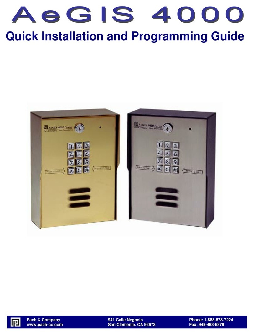
PACH & COMPANY AeGIS 4000 Operating instructions

PACH & COMPANY

PACH & COMPANY AeGIS 4000 Operating instructions

PACH & COMPANY AeGIS 8000 Series User manual

PACH & COMPANY

PACH & COMPANY AeGIS 8000 Series User manual

PACH & COMPANY AeGIS 9100CR200 Assembly instructions

PACH & COMPANY

PACH & COMPANY AeGIS 9100CR200 Assembly instructions

PACH & COMPANY AeGIS AFGR9 Assembly instructions

PACH & COMPANY

PACH & COMPANY AeGIS AFGR9 Assembly instructions

Popular Control System manuals by other brands

RuiDa KT332N user manual

RuiDa

RuiDa KT332N user manual

Omron TJ2-MC02 Hardware reference manual

Omron

Omron TJ2-MC02 Hardware reference manual

Cypress HHR-3160 product manual

Cypress

Cypress HHR-3160 product manual

Sound Associates CS-3 Operation manual

Sound Associates

Sound Associates CS-3 Operation manual

Merit MT-203 quick start guide

Merit

Merit MT-203 quick start guide

Johnson Controls ZZ Series installation manual

Johnson Controls

Johnson Controls ZZ Series installation manual

Altronics PowerQuest quick start guide

Altronics

Altronics PowerQuest quick start guide

Mitsubishi Electric AE-200A installation manual

Mitsubishi Electric

Mitsubishi Electric AE-200A installation manual

Siemens RRV851 operating manual

Siemens

Siemens RRV851 operating manual

SmarAct PICOSCALE user manual

SmarAct

SmarAct PICOSCALE user manual

AUMA EPAC Operation & instruction manual

AUMA

AUMA EPAC Operation & instruction manual

Strava 100.600E user manual

Strava

Strava 100.600E user manual

Pilz PNOZ mmc2p operating manual

Pilz

Pilz PNOZ mmc2p operating manual

Digitroll SEED MASTER Plus 8.6 Series user manual

Digitroll

Digitroll SEED MASTER Plus 8.6 Series user manual

btsr SMART KTF 2000 operating manual

btsr

btsr SMART KTF 2000 operating manual

Woodward SYNCONpanel Brief manual

Woodward

Woodward SYNCONpanel Brief manual

Pentatech GA50 instruction manual

Pentatech

Pentatech GA50 instruction manual

AVer CB-310 quick guide

AVer

AVer CB-310 quick guide

manuals.online logo
manuals.online logoBrands
  • About & Mission
  • Contact us
  • Privacy Policy
  • Terms and Conditions

Copyright 2025 Manuals.Online. All Rights Reserved.