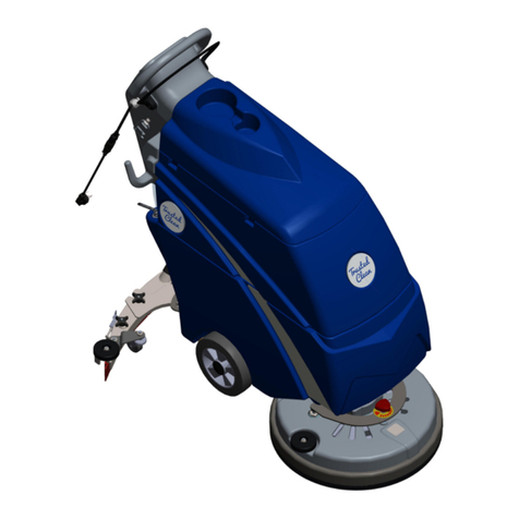
Pacific Steamex DYNAMO Operating instructions

REPAIR MANUAL
DYNAMO
&
TRIUMPH 440
03/01
The contents of this manual are based on the latest product
information available at the time of publication. Pacific
Steamex reserves the right to make changes or
improvements to its machines without notice.
FOR YOUR CONVENIENCE, RECORD THE
FOLLOWING INFORMATION:
MODEL_______________________________
SERIAL NUMBER______________________
PART NUMBER________________________
DATE PURCHASED_____________________
This Repair Manual is a supplement to the Operating &
Maintenance Instructions. Refer to the Operating &
Maintenance Instructions for the preparation, operation and
standard maintenance instructions. If you do not follow
the instructions, you can cause an injury or damage
equipment, furniture or buildings.
Maintenance and repairs must be done by authorized
personnel only. To prevent injury, always unplug the
machine before doing any repairs.
For new books write to:
Pacific Steamex, Inc.
2259 S. Sheridan
Muskegon, MI 49442-6252

1. Empty both the solution and recovery tanks.
2. To access the belt, the machine will either need to be placed upside down
or laid on its’ side. If you prefer to lay the machine upside-down, first
remove the handle (Drawing 1, Item 4) from the recovery tank to avoid
bending it. You will need to take out two sets of hardware (Drawing 1,
Items 1,2,3 & 80).
3. Lower the operator’s handle (Drawing 1, Item 16) down out of the way.
4. Place the machine either upside-down or on its’ side.
6. Loosen the two sets of brush motor bracket mounting bolts and washers.
Reference Drawing 2, Items 18, 19 & 20.
5. Remove the four sets of screws and washers that attach the brush
housing assembly to the body of the machine. Note that the brush housing
assembly is still attached to the body with hoses.
7. Take off the brush guard by removing these two screws, Reference
Drawing 2, Item 28.
BELT REPLACEMENT
Note: If adjusting the belt tension, slide the motor away from the brush to
tighten the belt or toward the brush to loosen. Keep the motor
perpindicular to the belt.
NOTE: DO NOT OVERTIGHTEN WHEN REASSEMBLING.
Reference Drawing 1, Page 8
#52 #56
#55 #56
2
Note: Throughout this manual there are references to Drawing 1 and Drawing 2. See Page 8 for Drawing 1
and Page 10 for Drawing 2.

8. Now take out the two axle shaft retaining screws located on either side
of the brush housing to release the brush assembly.
9. Remove the old belt, loop the new belt over the brush cog and drive
pulley. Reassemble, being careful not to pinch or kink any hoses.
BELT REPLACEMENT
3

BRUSH MOTOR REPLACEMENT
1. Follow steps 1-6 in the “Belt Replacement” section, however remove the
brush motor bracket bolts in step 6 on page 2. Then proceed as follows.
3. Remove the ground wire from the ground post in the
brush housing. Reference Drawing 2, Item 21.
4. Remove the nut and washer that hold the brush motor to its’ bracket.
Reference Drawing 2, Items 5 & 6.
5. Replace the brush motor. Make sure all the hardware is tightened and
the wiring is reconnected. Reassemble the machine, being certain not to
pinch or kink any hoses.
4
2. Disconnect the white and black leads.

PUMP REPLACEMENT
1. Remove the brush housing assembly. Refer to “Belt Replacement”,
steps 1-5.
2. Disconnect the black and white leads from the pump.
3. Now remove the hoses from the pump. Loosen each hose clamp.
Slightly heat the hoses up, then twist and pull the hoses off the elbows.
Remove the pump.
5. Remove the pump assembly from the bottom of the machine. Install the
new pump and follow the previous steps in reverse order. Make sure all
wire connections are properly plugged in and the hose connections are
secure. Make sure the hoses aren’t pinched or kinked when the housing is
reassembled to the machine.
4. Lift off the recovery tank, the pump cover plate is accessible (Drawing
1, Item 62). Remove the four screws (Drawing 1, Item 106) that connect
the pump assembly to the cover plate.

VACUUM MOTOR REPLACEMENT
1. Remove the brush housing assembly. Refer to “Belt Replacement”,
steps 1-5.
2. Remove the rear cover, reference Drawing 1, Item 37.
Follow these steps:
3. The wiring can now be seen. Disconnect the two black leads on the
vacuum motor from the black and white leads. Tape the black and white
leads off to the side for easier reconnecting later.
d) Now remove the screws that hold the rear cover to the body.
e) Spray the two grommets (Drawing 1, Item 36) with glass cleaner
(this will keep the grommets in place).
f) Slide the cover away from the machine.
a) Disconnect the quick connects on the hose (Drawing 1, Items 34 & 35).
b) Take off the hose clamp.
c) Remove the hose strap (Drawing 1, Item 31).
4. Remove the two sets of hardware (Drawing 1, Items 56, 54 & 59) that
connect the solution tank to the body.
Screws
Grommets
Rear Cover
Hose Clamp
Quick
Connects
Hose
Strap
6

7. Remove the screw that holds the solution tank bracket (Drawing 1, Item
70) to the body of the machine.
9. Remove the three vacuum motor mounting sets (Drawing 1, Items 68 &
53). The vacuum motor can now be lifted off its studs. If it is difficult to
remove, the vacuum hose may need to be repositioned. From underneath
the machine, slide the hose to the far left, inside the base (from the
operators position).
10. Install the new vacuum motor and gaskets, ensuring not to pinch wires
between the motor and machine body. Follow the above steps in reverse
order. Make sure all wiring connections are secure and hardware is
tightened.
5. Return the machine to the upright position and lift off the recovery
tank.
VACUUM MOTOR REPLACEMENT
6. Take out the two screws that attach the control panel (Drawing 1, Item
10) to the solution tank.
8. The solution tank can now be rotated sideways to access the vacuum
motor.
7

69
72
51
55
9
DRAWING 1 - Machine
8
123
80
4
5
6
77
73-75
76
81
82
83
84
67
53
68
Vacuum Motor
Mounting Sets (3):
10 11
12 13
7
14
15
16 17
95
96
97
18
19
21 20
79
22
8
9
26 28
8
27
89
88
78
93
71
70
23
24
90
25
41
29
11
34
60
21
30
31
35
32 24
33
85
90
36
37
38
39 40
63, 64
65
66
11
49
42 48
44
43
41
45
46
47
42
86
87
26 62
60
94
59
54
56
50
53
54
56
57
58
PUMP: Access from bottom of machine
by removing brush housing,
then remove 4 plate screws
located under recovery tank.
101
102 103
104
105
106
54
53
52
91
90
92
17
Inline Strainer Assembly
03/01
61
98
99
100

DRAWING 1 - Machine Parts List
03/01
ITEM PART NO. DESCRIPTION QTY.
1 962007 Screw 2
2 980004 Washer, 1/4 Flat 2
3 248201 Spacer, Tank Handle 2
4 243902 Handle, Recovery Tank 1
5 242701 Dome 1
6 243402 Gasket, Dome 1
7 612001 Clamp, Cable 2
8 920619 Nut, 1/2 Pipe Lock 1
9 248502 Strain Relief, Straight 2
10 246605 Plate, Control 1
11 W351D Screw, 10-24 x 1/2 THP 11
12 911089 Switch, Rocker 2
13 920030 Flange Nut 1
14 962147 Screw, 10-32 x 1.75 PHP 8
15 240806 Bracket, Cord Wrap 1
16 243901 Handle, Black 1
17 W136D Screw, #8 x 1/2 THP 10
18 3704 Switch, Momentary 1
19 206651 Plate, Switch 1
20 248505 Stiffener, Handle 2
21 242402 Cuff, Hose (to dome) 2
962119 Screw, Hose to Dome 1
22 244108 Hose, 1.25x4' 1
23 247003 Pivot, Handle LH 1
247004 Pivot, Handle RH 1
24 980612 Washer, Thrust 4
25 960033 Screw, 1/2x1-1/2 Shoulder 2
26 W136D1 Screw, #8 x 1/2 THP 2
27 508519 Strain Relief 1
28 908083 Cord Asm, Handle 1
29 246602 Plate, Strain Relief 1
30 W107D Washer 4
31 248504 Strap, Hose 2
32 241307 Body (used with pump 247006) 1
33 S223P Brass Barb, 1/4 to 1/4 MPT 1
34 203302 Quick Connect, 1/4 Male 1
35 203308 Quick Connect, 1/4 Female 1
36 243801 Grommet 2
37 242302 Cover, Rear 1
38 209771 Wheel, 6 x 1-1/2 Grey 2
39 240501 Axle, Wheel 1
40 S482P Snap Axle Cap 2
41 243304 Fitting 2
42 242901 Elbow 2
43 241305 Body, Inline Strainer 1
44 248506 Strainer Screen, Inline 1
45 243405 Gasket, Inline Strainer 1
46 241501 Clear Cap, Inline Strainer 1
47 3771 Elbow 1
48 S613A Coupling 1
49 240801 Bracket, Strainer 1
50 3771 Elbow, Under Sol'n Tank 1
51 244202 Housing, Brush 1
52 962152 Bolt, Tap 1/4-20 x 3-1/4 1
53 W104D Washer, 1/4 Flat 7
ITEM PART NO. DESCRIPTION QTY.
54 980002 Washer, 1/4 Lock 9
55 962151 Screw, 1/4-20 x 4 HHCS SS 1
56 W189D Screw, 1/4-20 x 3/4 HH SS 4
57 243403 Gasket, Vac Shoe 1
58 246606 Plate, Vac Shoe 1
59 W311D Washer 4
60 242401 Cuff, Hose 2
61 243408 Gasket, Pump Plate 1
62 247005 Plate, Cover 1
63 245203 Vac Motor 1
64 603473 Gasket, Under Vac Mtr. 1
65 243401 Gasket, Vac Transfer 1
66 248503 Screen, Vac Intake 1
67 248401 Stud, Threaded 3
68 920011 Nut, 1/4-20 Elastic Stop 3
69 248604 Solution Tank, Grey 1
70 240803 Bracket, Solution Tank 1
71 962006 Screw, 1/4-20x1/2 PHP 3
72 240202 Adaptor, Hose to Dome 1
203359 Fitting, Hose Barb 3/8 2
73 243301 Filter Asm, Solution 1
74 200871 Brackets, Filter 2
75 W136D Screw, #8 x 1/2 THP 4
76 248603 Recovery Tank, Grey 1
77 243307 Filter Asm., Standpipe 1
78 246701 Pin, Tank Locator 1
920019 Nut, 1/4-20 Hex Jam 1
79 908059 Cord Asm. 1
80 980005 Washer, W ave 2
81 962154 Screw, 6-32x5/8 PHP 1
82 247201 Retainer, Filter 1
83 W144D Nut, 6-32 Hex w/Nyloc 1
84 245109 Label, W arning 1
85 243406 Gasket, Exhaust 1
86 243602 Guard, Strainer 1
87 962153 Screw,10-24x1/2 Wsher. Hd. 2
88 245113 Lock, Handle 2
89 920017 Nut 2
90 W350D Screw 10-24x1/2 THP MS SS 10
91 242702 Door, Clean-Out 1
92 243407 Gasket 1
93 962022 Bolt 2
94 223470 Gasket 1
95 W343D Screw, 10-24x1 PHP 2
96 980015 Washer #10 Ext. Tooth 2
97 W106D Nut, 10-24 Hex S/S 2
98 249401 Valve, Check Inline 1
99 980035 Washer, Int. Tooth 2
100 242002 Clamp 1
101 247006 Pump, 60 psi 1
102 240810 Bracket, Pump Mounting 1
103 S535P Brass Barb 1/4 to 3/8 MPT 1
104 242902 Elbow, 1/4 MPTx1/4 Barb 90 1
105 S804N Plug, 3/8 Brass HH 1
106 962001 Screw, 10-24x1/4 FHP 4
Not Shown: Hoses:
244110 Hose, Strainer to Pump 0.75 ft.
244104 Hose, Pump to QC 1.92 ft.
244105 Hose, Tee to QC 2.75 ft.
244102 Hose, Tank to Strainer 1.17 ft.
244107 Hose, Adaptor Fill 5.5 ft.
Not Shown: Labels:
205171 Label, Push to Clean 1
245111 Label, Instructions 1
245112 Label, Defoamer 1

Brush Housing Assembly
7
89
10
11
12
13
6
16
17
18
19
21
22
23
24
25 26
27
28
29
30
22
23
10
1
23
4
56
18
20
14
15
03/01

Brush Housing Assembly
Parts List
11
03/01
ITEM PART NUMBER DESCRIPTION QTY.
1 903009 Belt 1
2 246901 Pulley, Drive 1
3 240804 Bracket, Motor Mting 1
4 245202 Motor, Brush Drive 1
5 W329D Nut, 10-32 Hex 2
6 980015 Washer, #10 Ext. Tooth 5
7 920017 Nut, 10-24 ESNA S/S 4
8 240812 Bracket, Top Single Jet 1
9 S296P Brass Barb 1/4 to 1/8 MPT 1
10 243306 Fitting-Elbow 1/8 1
11 240811 Bracket, Bottom Single Jet 1
12 244202 Housing, Brush 1
13 W106D Nut, 10-24 HEX S/S 3
14 W153D2 Screw, 10-24x3/4 PHP 4
15 244902 Jet-Spray 11004 1
16 W353D Screw, 1/4-20x1/2 FHP 2
17 980032 Washer, 1/4 Flat Ext. 2
18 980075 Washer, 3/16 Fender 4
19 W124D Washer-Lock,#10 Int.Tooth 2
20 962150 Screw, 10-24x1/2 HH SS 2
21 962113 Grounding Screw 1
22 213601 Guard, Brush 2
23 980612 Washer, Thrust 2
24 962062 Screw, Pan Hd. 3
25 3743 Cog, Brush 1
26 3677 Bearing, Rulon Sleeve 2
27 243601 Guard, Belt 1
28 W199D1 Screw, 8-32 x 1/2 THP 2
29 3731 Brush 1
30 217701 Shaft, Brush 1

WIRING DIAGRAM
WIRING DIAGRAM
MACHINE WITH OPTIONAL HOUR METER
03/01 245604
Other manuals for DYNAMO
1
This manual suits for next models
1
Table of contents
Other Pacific Steamex Floor Machine manuals

Pacific Steamex
Pacific Steamex TRIUMPH 430 Installation and operation manual

Pacific Steamex
Pacific Steamex NIGHTHAWK 20 Installation and operation manual

Pacific Steamex
Pacific Steamex TRIUMPH 870 Installation and operation manual

Pacific Steamex
Pacific Steamex DYNAMO Installation and operation manual
Popular Floor Machine manuals by other brands

Clarke Technology
Clarke Technology Alto IMAGE 20i ErgoEX Operator's manual

PowerBoss
PowerBoss Phoenix 28 instruction manual

Nilfisk-Advance
Nilfisk-Advance FM800 REV 56382452 Instructions for use

Media
Media 22E-24E Use and maintenance manual

IPC
IPC CT15 B quick guide

Columbus
Columbus AKS 80 operating manual