Pacific Steamex NIGHTHAWK 20 Installation and operation manual

NIGHTHAWK
20”, 24” & 27”
PROPANE BURNISHERS
OPERATING & MAINTENANCE
INTRODUCTION INSTRUCTIONS
READ THIS BOOK
This operator’s book has important information for the use
and safe operation of this machine. Read and understand
the Engine Operator’s Manual and this manual before
starting the machine. Keep this book and tell all opera-
tors to read the book. If you do not follow the instruc-
tions, you can cause an injury or damage equipment,
furniture or buildings.
For new books write to:
Pacific Steamex, Inc.
2259 S. Sheridan
Muskegon, MI 49442-6252
Carefully inspect all components to ensure that there is
no concealed freight damage. If such damage is discov-
ered, file a “CONCEALED DAMAGE REPORT”
immediately with the delivering carrier.
The contents of this manual are based on the latest product
information available at the time of publication. Pacific
Steamex reserves the right to make changes or improve-
ments to its machines without notice.
FOR YOUR CONVENIENCE, RECORD THE
MACHINE AND ENGINES MODEL AND SERIAL
NUMBERS HERE:
MACHINE MODEL______________________
MACHINE SERIAL NUMBER_____________
ENGINE MODEL________________________
ENGINE SERIAL NUMBER_______________

TABLE OF CONTENTS
IMPORTANT SAFETY INSTRUCTIONS……………………………………………………………. 3
OPERATING PROCEDURES…………………………………………………………………………. 5
A. Check the Engine Oil……………………………………………………………………………..5
B. Properly Fill and Check LP Tank and Lines for Leaks………………………………………..…5
C. Connecting the HP Hose to LP Tank……………………………………………………………..5
D. Installing Pads…………………………………………………………………………………….5
E. Starting the Engine………………………………………………………………………………. 5
F. Stopping the Engine………………………………………………………………………………6
G. Transporting the Machine……………………………………………………………………….. 6
H. Storing the Machine………………………………………………………………………………6
.
MAINTENANCE………………………………………………………………………………………... 6
A. Machine Maintenance…………………………………………………………………………… 6
B. Changing the Drive Belt……………………………………………………………………….…6
C. Changing the Angle of Attack & the Head Pressure……………………………………………. 7
NIGHTHAWK ILLUSTRATION GUIDE……………………………………………………………. 8
PAD DRIVER ASSEMBLY…………………………………………………………………………… 9
RAIL & HUB ASSEMBLY……………………………………………………………………………. 10
HANDLE & THROTTLE ASSEMBLY……………………………………………………………… 11
WHEEL ASSEMBLY………………………………………………………………………………….. 11
TANK ASSEMBLY……………………………………………………………………………………. 12
BRACKET ASSEMBLY………………………………………………………………………………. 12
HANDLE BRACKET & HP HOSE ASSEMBLY…………………………………………………… 13
REGULATOR ASSEMBLY……………………………………………………………………………13
STARTER ASSEMBLY……………………………………………………………………………….. 14
ENGINE………………………………………………………………………………………………… 14
HONDA ENGINE DISTRIBUTORS…………………………………………………………………. 15
WARRANTY POLICY………………………………………………………………………………... ..16
2

IMPORTANT SAFETY INSTRUCTIONS
READ AND UNDERSTAND ALL INSTRUCTIONS AND WARNINGS BEFORE
OPERATING THIS MACHINE!
WARNINGS:
1. DO NOT STORE OR USE GASOLINE OR OTHER FLAMMABLE VAPORS AND LIQUIDS IN THE VI-
CINITY OF THIS MACHINE.
2. NO SMOKING, NO SPARKS, NO FLAMES NEAR UNIT OR LP TANK.
3. OPERATE ONLY IN WELL VENTILATED AREAS. BUILDINGS MUST BE PROVIDED WITH :
A) A CONTINUOUS MECHANICALVENTILATION THAT REMOVES THE PRODUCTS OF COMBUS-
TION TO THE OUTDOORS OF NOT LESS THAN 300 CFM FOR EACH 10,000 BTUH OR FRAC-
TION THEREOF; OR
B) NATURAL VENTILATION OF NOT LESS THAN 300 CFM FOR EACH 10,000 BTUH INPUT OR
FRACTION THEREOF, BASED ONAMAXIMUM OF ONE-QUARTERAIR EXCHANGE PER HOUR
FOR THE NET BUILDING VOLUME.
4. IFYOU SMELL LP GAS, STOPTHE UNITAND CHECK FOR LEAKS. ALSO OPEN WINDOWS, DON’T
TOUCH ELECTRICALSWITCHES, EXTINGUISH ANY OPEN FLAMES. CALLYOUR GAS SUPPLIER
IF NO LEAKS ARE FOUND.
5. DO NOT ADJUST THE FUEL SYSTEM WITHOUT THE PROPER ANALYSIS EQUIPMENT.
6. NEVER TURN THE UNIT ON ITS SIDE.
7. KEEP HANDS AND FEET CLEAR OF ALL MOVING PARTS.
8. TURN THE GAS OFF AT THE TANK TO KILL THE ENGINE.
9. REMOVE THE LP TANK AND STORE IT IN AN APPROVED AREA WHEN NOT IN USE. A “NO SMOK-
ING” SIGN SHOULD BE PERMANTLY DISPLAYED AT THE STORAGE AREA.
10. KEEP ALL OBJECTS CLEAR OF THE EXHAUST SYSTEM DURING AND AFTER OPERATION.
11. DO NOT LEAVE THIS MACHINE UNATTENDED WHILE THE ENGINE IS RUNNING.
12. WHEN THE LP TANK IS ATTACHED TO THE MACHINE AND NOT RUNNING, THE OPERATOR
SHOULD NOT LEAVE THE MACHINE UNATTENDED EXCEPT FOR SHORTPERIODS OFTIME SUCH
AS REST STOPS, WASHROOM OR MEAL STOPS.
13. THE OPERATOR MUST COMPLETELY UNDERSTAND ALL INSTRUCTIONS, WARNINGS AND OP-
ERATING PROCEDURES BEFORE USING THIS MACHINE.
14. THIS MACHINE MUST BE MAINTAINED INACCORDANCE WITHTHIS MANUALS RECOMMENDED
MAINTENANCE INSTRUCTIONS AND THE ENGINE MANUFACTURERS RECOMMENDED MAIN-
TENANCE PROCEDURES. FAILURE TO DO SO MAY CAUSE DAMAGE TO THE MACHINE, EQUIP-
MENT, FURNITURE, BUILDINGS OR PERSONAL INJURY!
3

NOTES
4

5
OPERATING PROCEDURES
WARNING! Follow the instructions given in this book-
let, the Engines Owners Manual and the training given
by your supervisor for the safe operation of this ma-
chine. Failure to do so can result in personal injury and/
or damage to the machine or property.
DO NOT OPERATE THIS MACHINE IN AN
EXPLOSIVE ENVIRONMENT!
The NightHawk Propane Burnishers are intended for
commercial use.
A. CHECK THE ENGINE OIL BEFORE EVERY
OPERATION!
Make sure the machine is level when checking the oil.
Always take 2 readings of the dip stick before adding
oil. If the oil level is below the full mark, add just
enough oil to the engine to bring the oil level up to the
full mark. Never over fill. Follow the guidelines in
your Engine Owners Manual. Check for foreign ma-
terial on the dipstick.
B. PROPERLYFILLAND CHECKYOUR LPTANK
AND ALL LP FUEL LINES FOR LEAKS!
1. Every tank we sell has been pressure and leak
tested. However, every time a tank is filled and/or
connected to the machine it should be soap tested.
All LP lines must be pressurized and every inch of
line and connections must be sprayed. If you find a
leak, make the proper repairs before operating the
machine. NOTE: The connection and disconnection
of the LP tank must be done in a well ventilated area
with NO source of ignition within 10 feet (3 meters)
from the point of connection.
2. Never over fill the LP tank. Your buffer’s LP
tank is designed to hold just 20 pounds of propane.
Make sure to weigh the tank as it is being filled.
The gross weight of a full tank should not exceed 48
pounds. If while operating the machine you notice
frost forming on the LP lines or the regulator, your
tank has been over filled. If you continue to operate
the machine in this condition damage will occur.
The excess propane in the tank must be removed
before normal operations resume. The bleeding of a
propane tank should be done in a safe location
outside the building. In some cases the regulator
must defrost befor restarting the engine.
C. CONNECTING THE HIGH PRESSURE HOSE
TO THE LP TANK: Make sure the couplers are in
line and screwed together hand tight (see page 13). If
this is not done properly, fuel will not pass through to
the regulator.
D. INSTALLA FRESH PAD BEFORE EVERY JOB;
if not new, at least clean. To install a fresh pad, set the
machine down in the rear. Unscrew and remove the
yellow pad-centering ring. See page 9, the “Pad
Driver Assembly”. Remove the old pad and center
the new pad onto the pad driver. Reinstall the yellow
pad-centering ring. Never “flip” a pad. Keep the same
side down throughout the life of the pad. Even after a
pad is cleaned, you can tell the down side by the cen-
tering ring indentation. This practice will increase
the pad life and help maintain a properly functioning
pad driver. NEVER TILT A MACHINE ON ITS
SIDE!
E. STARTING THE HONDA ENGINE.
1. Make sure you have completed items A,B,C and
D above. Also make sure the fuel is on at the
tank. Set the machine down in the rear. If your
unit is equipped with a centrifugal clutch, set down
is not necessary.
2. Push the throttle lever all the way forward to en-
gage the choke (see page 11).
3. Plug the starter cord into a 115-volt outlet (page
14).
4. Push the starter button.
5. When the engine starts, release the starter button
and adjust the throttle back to a high idle. Un-
plug the cord.
6. Lower the buffing deck to the floor and set the
throttle to the desired buffing speed. Always keep
the machine moving while the pad is touching
the floor.
7. Keep hands, fingers and feet clear of all moving
parts while the machine is in operation.

OPERATING PROCEDURES
F. STOPPING THE ENGINE.
1. Pull the throttle back and low idle the engine.
2. Turn the propane tank valve clockwise to a closed posi-
tion.
NOTE: The exhaust system will be very hot and takes several
minutes to cool, so keep yourself and all materials clear!
G. TRANSPORTING THE MACHINE.
1. The tank should be securely fastened.
2. The tank valve must be closed.
The transport area should be well ventilated
H. STORING THE MACHINE.
1. The engine should be stopped properly
and the tank valve closed.
2. Remove the LP tank from the machine
and store the tank in an approved area.
3. Store your machine in a safe area: away
from enclosed high heat, away from sparks
or flames, away from traffic lanes of heavy
equipment.
REFER TO SAFETY INSTRUCTIONS!
MAINTENANCE
A. MACHINE MAINTENANCE
1. Change the oil and filter according to the Honda Engine
Owners Manual. Change the oil at the first 20 hours of
operation. Thereafter, oil should be changed at 50-hour
intervals.
2. Grease the wheels every 50 hours of operation.
3. Keep the cooling air filter (on top of the engine) clean at
all times. Wet clean it at the end of every use. Never oper-
ate the machine unless the filter is clean and properly in-
stalled.
4. Each week wet clean the carburetor foam pre-filter with
soap and water. Blot dry with paper towels and reinstall.
Do not treat this filter with oil. Never operate the unit
unless the paper element and the pre-filter are properly in-
stalled. Install a new paper element every 200 hours of
operation.
5. Clean the entire unit after each use.
6. When cleaning the unit, check for possible loose nuts and
bolts.
7. Check the pad driver weekly for rigidity and wear. Re-
place the harpoon face as needed.
8. Check the bearing hub shaft and bearings weekly. If the
shaft shows any looseness, the bearings and possibly the shaft
must be replaced.
Remember that being safe is a full-time, every
day job. Follow all information posted on the
machine and the LP tank.
9. Soap test for LP leaks at least every time
you install a fresh LP tank. To do this test
properly, the LPlines must be pressurized and
every inch of line and connections must be
sprayed. If you find a leak, make the proper
repairs before operating the machine. Also
see Item B under Operating Procedures.
Neverallowanyonetooperatethis machine that
has not read or cannot understand the given
instructions.
B. CHANGING THE DRIVE BELT.
1. The engine should be off and the ma-
chine level with the floor.
2. Remove the front cover (7/16-inch
wrench).
3. Loosen only (do not remove) the 4 hub
plate mounting bolts (3/4-inch wrench).
These are the front 2 bolts located on the right
and left sides of the main frames above the
hood. The third bolt on either side mount
the push bar and should not be loosened.
6

7
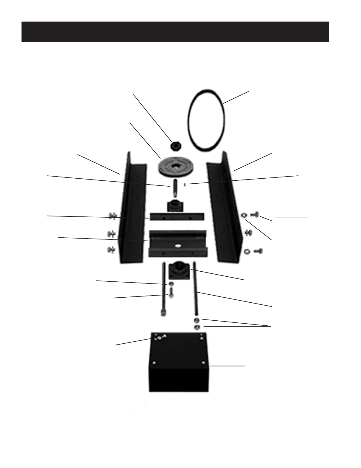
B. Changing the Drive Belt Continued.
4. Turn the 2 tension rods counter clockwise equal
turns until you can push the bearing hub plate to the
rear (3/4-inch socket).
5. Remove the old belt and install the new one.
6. Tension the new belt by reversing step #4. The
belt should be just tight enough to not slip or squeal.
Care must be taken not to over tension the belt. Over
tension will cause premature bearing wear.
7. Retighten the 4 bearing hub plate mounting bolts.
8. Replace the front cover.
C. CHANGING THEANGLE OFATTACK (PAD TO
FLOOR) & THE HEAD PRESSURE.
If the machine has been dropped or you notice a dis-
tinct increase in the torque during operation, this ad-
justment may be needed. For this operation, you will
need: a ¾-inch wrench, a new pad installed on the
machine, a framing level, a wood block and shims,
and a level floor
area on which to set the machine. The end results of
this operation should be a machine with framework
that sets slightly low in both the rear and on the right
side. The right frame should be 1/8-inch lower than
the left frame at the wheel bracket point. You may
measure the distance from the top of the axle plate to
the top of the main frame to establish this difference.
Th 1/8-inch variance from the left to the right is criti-
cal for level buffing and ease of operation. If the dif-
ference is increased (more than 1/8- inch), torque re-
lief will increase but level buffing will decrease; you
will shine harder on the right side of the machine than
the left. If the difference is decreased (less than 1/8-
inch), torque relief will decrease and level buffing will
increase. The machine will be harder to operate. When
you get it right, the machine will deliver good level
buffing with a minimum of operating effort.
1. Install a new pad onto the machine.
2. Place the machine onto a level floor area.
3. Remove the LP tank.
4. Place the wood block and shims under the tails of
the right and left main frames of the machine; enough
to slightly raise the wheels from the floor.
5. Loosen the right and left axle brackets, two bolts
each.
6. Level the left main frame with the framing level.
You will need to remove the wood shims as this is
done. Tap the wheel up or down as needed to main-
tain floor contact. The frame should be slightly low in
the rear (about ¼ inch below level at the tail).
7. When this measure is achieved, tap the left wheel
to the floor and tighten the mounting bolts.
8. Now measure the distance between the top of the
left wheel bracket and the top of the left main frame.
9. Subtract 1/8-inch from the measurement in step
#8. Set the right wheel bracket to this new mea-
surement.
10. Tighten all wheel bracket mounting bolts and re-
move the wood block and shims.
If the unit seems to over torque after a test run, you
may correct this problem by simply raising both wheel
brackets equal amounts. This adjustment changes the
angle of attack pad to floor and should be made in
small 1/8-inch increments. Always keep the right
frame 1/8-inch lower than the left at the wheel bracket
point.
If you desire to increase the head pressure of your
unit, simply move the right and left axle brackets to
the rear equal amounts. Make this move in ½ inch
increments. Test run the unit after each adjustment
until you reach the desired head pressure. If you find
that you have increased the head pressure and increased
the torque, the torque may be decreased by raising both
the right and left wheels equal amounts. The wheel
system on this unit is designed for the professional.
There are enough adjustments to make the machine
buff any way you want. The ability to control the head
pressure and angle of attack ate advantageous to level
buffing, ease of operation, and superior pad life.

NIGHTHAWK
HANDLE & THROTTLE
See Page 11
HANDLE BRACKET AND HP HOSE
See Page 13
REGULATOR ASSEMBLY
See Page 13
STARTER ASSEMBLY
See Page 14
RAIL & HUB ASSEMBLY
See Page10
TANKASSEMBLY
See Page 12
BRACKETASSEMBLY
See Page 12
ENGINEASSEMBLY
See Page 14
and
Engine Owners Manual
WHEEL ASSEMBLY
See Page 11
PAD DRIVER ASSEMBLY
See Page 9
MACHINE DESCRIPTION: PARTNUMBER:
NightHawk 20” with 11 HP Honda Engine 275414
NightHawk 20” with 13 HP Honda Engine 275415
NightHawk 24” with 13 HP Honda Engine 275417
NightHawk 27” with 13 HP Honda Engine 275420
8

PAD DRIVER ASSEMBLY
Flex Belting, 3/16 (2)
#270216
Flex Retainer, Steel (24”&27” only)
#271210
Screw,1/4-20x3/4 HH
#W189D
Washer, 1/4 Lock
#980002
Washer, 1/4 Fender Zinc
#W311D
Six (6) Sets:
Three (3) Sets:
Screw, 10-24x1-1/2 RHP
#W384D
Washer, #10 Flat
#W401D (20” Only)
Washer, 1/4 Flat
#980004 (20” Only)
Coupler, Steel Puck
#200059
Pad Driver
20”- #200129
24”- #271197
27”-#271198
Spacer
#271081
Washer, #10 Flat
#W401D
Washer, #10 Spring Lock
#980022
Nut, 10-24 Hex
#W106D
Eight (8) Sets:
Screw,10-24x1 PHP
#W189D
Washer, #10 Flat
#W401D (20” Only)
Washer, 1/4 Flat
#980004 (20” Only)
Washer, #10 Flat
#W401D
Washer, #10 Spring Lock
#980022
Nut, 10-24 Hex
#W106D
Yellow Center Grip Base
#271082
Harpoon Dish
20”- #270222
24”- #270211
27”- #270223
Burnishing Pads
Case of Five
20”- #200128
24”- #271159
27”- #271160
Nut, 3/4-10 Hex
#920021
Yellow Center Ring Lock
#271083
Not Shown:
Hood
20”- #200130
24”- #271086
27”- #271085
Hood Mounting Sets (4):
Screw, 5/16-18x1/2 HHCS
#962129
Washer, 5/16 Lock
#980006 9

RAIL & HUB ASSEMBLY
Drive Belt
20”, B-42: #200134
24” & 27”, B-47: #270162
Pulley Flange
#270214
Drive Pulley
20”- #270224
24” & 27”- #270213
Frame Left
#271094L
Frame Right
#271094R
Shaft
#270209 Shaft Key
#271105
Six (6) Sets:
Screw, 1/2-13x1 HHCS
#962131
Washer, 7/16 Flat
#980073
Push Bar
#271074
Bearing Plate
#270210
Bearings, Flange (2)
#270212
Two (2) Sets:
Tension Rod, 1/2x12
#271073
Nuts, 1/2-13 Hex
#920022
Hex Nut, 7/16-14
#270219
Bolt, 7/16-14x1 3/4 HH
#270218
Four (4) Sets:
Screw, 1/4-20x1/2 HH
#W183D
Washer, 1/4 Flat
#W104D Front Cover
#271095
10

11
HANDLE & THROTTLE ASSEMBLY
WHEEL ASSEMBLY
Handle Grip, Pair
#271001
T-Bar
#200002
Washer Plate
#271004
Two (2) Sets:
Screw, 3/8-16x1 3/4
#962018
Washer, 5/16 Flat
#980007
Throttle & Cable
#270221
Screws (3)
#962128
Clamp
#271164
Nut Plate
#271054
Axle Bracket
#271053
Two (2) Sets:
Screw, 1/2-13x1 1/2 HHCS
#962132
Washer,7/16 Flat
#980073
Wheel & Bearing
#271051
Washer (2)
#271052
Collar, Shaft
#271161

12
TANK ASSEMBLY
Male Coupler
#271047
(included with tank)
Tank Safety Valve
Part of Tank #271045
Warning Decal
(not shown)
#271178
LP Tank, 20#
Fittings Included
#271045
Bracket Assembly Complete
#271030
Two (2) Sets:
Bolt, 3/8-16x2 1/4 HH
#962103
Washer, 5/16 Flat
#980007
Bracket Extender Tubes
#200018
Washer, 5/16 Flat
#980007
Nut, 1/2-13 Hex
#920002
Tank Bracket
#271030
Bracket Barrel Nut
#271034
Bracket Clasp
#271033
BRACKET ASSEMBLY

13
HANDLE BRACKET & HP HOSE ASSEMBLY
T-Bar
#200002
Handle Bracket
#271019
Not Shown,
Four (4) Sets:
Screw, 3/8-16x1 1/4
#271020
Washer, 5/16 Flat
#980007
Nut, 3/8-16 Hex
#920002
High Pressure (HP) Hose
(Tank to Regulator, 12”)
#271050
Elbow, 1/4 MPTx3/8M 45
#271170
Female Coupler
#271048
Regulator
#200019
Male Coupler
#271047
Regulator
#200019
High Pressure Fuel Hose
#271050 Low Pressure Fuel Hose
#200026
Hose Clamp (2)
(Each end of LP Hose)
#S453P
LP Hose Fitting
#203361
Elbow,
1/4 MPTx3/8M 90
#271173
Vacuum Hose, 5/32
#200028
Elbow,1/8MPTx1/4
#200023
REGULATOR ASSEMBLY

14
STARTER ASSEMBLY
Engine:
11 HP Honda (20” only)
#200080
13 HP Honda (20”,24”&27”)
#270220
Engine Mounting Bolts:
Right Side
Front Set (1):
Screw, 5/16-18x1 1/2 HH
#962049
Washer, 1/4 Flat
#980004
Washer, 5/16 Lock
#980006
Nut, 5/16-18 Hex
#920003
Rear Set (1):
Screw, 5/16-18x2 HH
#W206D1
Washer, 1/4 Flat
#980004
Washer, 5/16 Flat
#980007
Washer, 5/16 Lock
#980006
Nut, 5/16-18 Hex
#920003
Engine Mounting Bolts:
Left Side
Two (2) Sets:
Screw, 5/16-24x1 HHCS
#200081
Washer, 1/4 Flat
#980004
Washer, 5/16 Lock
#980006
Ring Terminal
#271192
Bushing, Oil Drain
#200070
Hour Meter
#271099
Meter Leads (2):
1. #271101 positive lead
w/male bullet terminal
#271189.
2. #271101 negative lead
connected to ring terminal
#271192 (located above).
Engine Pulley, BC-34
#200084
Key
#271105
Starter, AC
#200083
Starter Mounting Kit, 2 Sets:
Screw, 5/16-18x1 HH
#962021
Washer, 1/4 Flat
#980004
(BRACKET)
Washer, 1/4 Flat
#980004
Washer, 5/16 Lock
#980006
Nut, 5/16-18 Hex
#920003
Starter Mounting Kit, 2 Sets:
Screw, 6MM-1x20MM HHCS
#270217
Washer, 1/4 Lock
#980002
Washer, 1/4 Flat SAE SS
#W104D
(BRACKET)
ENGINE
Right Side View
F
R
O
N
T
R
E
A
R
Paper Air & Pre-Cleaner
#270238
Air Pre-Filter Only
#270239
Cooling Filter:
#270236 (11 HP Honda)
#270237 (13 HP Honda)

15
NOTES

WARRANTY POLICY
PACIFIC STEAMEX INC. LIMITED WARRANTY
This Pacific Steamex Inc. Industrial Maintenance Machine has been manufactured, tested and inspected in
accordance with specific engineering requirements and is WARRANTED to be free from defects in
workmanship and materials for periods as follows from the date of purchase:
Two (2) years-Honda Engine
One (1) year-all other items unless excluded.
This warranty extends to the original user/purchaser and only when used, operated and maintained in
accordance with Pacific Steamex Inc. Operating and Maintenance instructions.
This warranty does not apply to certain wear parts and accessories of the machine such as filters, belts, pad
drive face, pad centering devise, etc., nor does it apply to damage or failure caused by improper use, abuse
or neglect. Warranty credit or replacement of return parts including wheels, shafts, etc., is subject to
incoming inspection of those items.
To secure repair under this warranty, the following procedure should be taken:
1. The inoperative machine or warranted parts must be delivered to the authorized dealer with shipping
and delivery charges prepaid. If unable to locate the Dealer, you may contact Pacific Steamex Inc. at
the address listed herein for the location of the nearest Pacific Steamex Inc. repair center or agent or
for other instructions pertaining to your warranty difficulty.
2. For Engine Warranty repair deliver the machine to the nearest Honda Warranty Service Center
(reference page 15).
3. Upon compliance with the above warranty procedure, all warranted repairs will be completed at no
additional charge or cost to the user.
4. Only Pacific Steamex Inc. or its authorized dealers and agents may make no charge warranty repairs
on this product. All others do so at their own risk.
This warranty limits Pacific Steamex Inc. liability to the repair of the product and/or warranted parts
replacement and does not include incidental or consequential damages arising from the use of a Pacific
Steamex Inc. machine whether defective or not.
This warranty is in lieu of all other expressed or implied warranties and is extended to the original
purchaser/user.
PACIFIC STEAMEX, INC.
2259 S. SHERIDAN
MUSKEGON, MICHIGAN 49442-6252
800-968-1332
FAX 1-800-863-9536
8/00 270235
This manual suits for next models
2
Table of contents
Other Pacific Steamex Floor Machine manuals