PackshotCreator PackshotCompact Instruction Manual
PackshotCompact
QuickStart
INSTALLATION GUIDE
PackshotCompact
lightbox
© Sysnext. All rights reserved.
This material is not to be interpreted as a guarantee of earnings and may not be copied, reproducved, modied, published, uploaded, posted or
distributed in any way, without PackshotCreator’s prior consent.
PackshotCompact
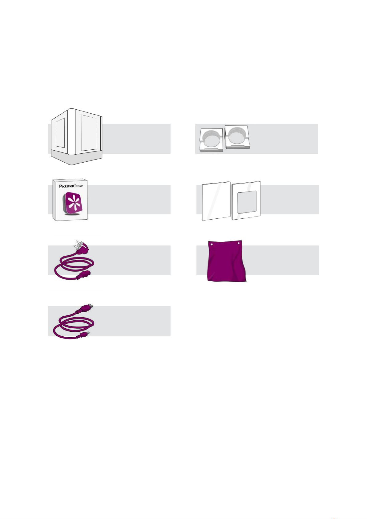
PACKAGE COMPOSITION
Product Registration Sheet
& Quick Reference Guide
1 power cable
1 USB cable
3 acrylic panels
2x
2 camera mount
sponges
Reective door
covers
PackshotCompact
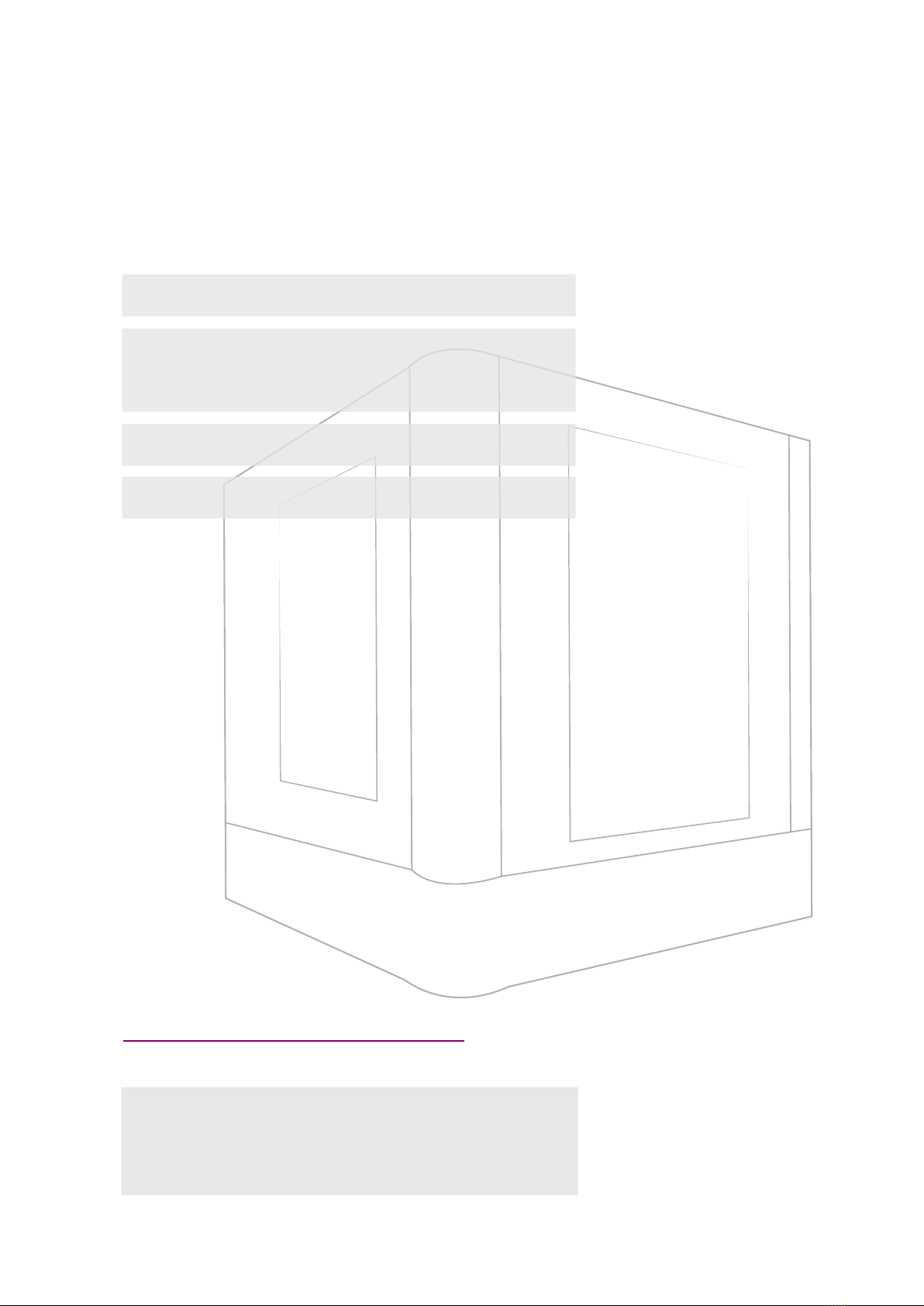
SPECIFICATIONS
Dimension (L x W x H): 100cm x 100cm x 120cm
Maximum Target Size
Top Shots: 56cm x 56cm
Side Shots: 56cm x 56cm x 80cm
Total Weight: 100 kg
Maximum Object Weight: 20.4 kg
Email: help@packshot-creator.com
Website: http://esupport.packshot-creator.com
CONTACT INFO:
PackshotCompact
SYSTEM PLACEMENT
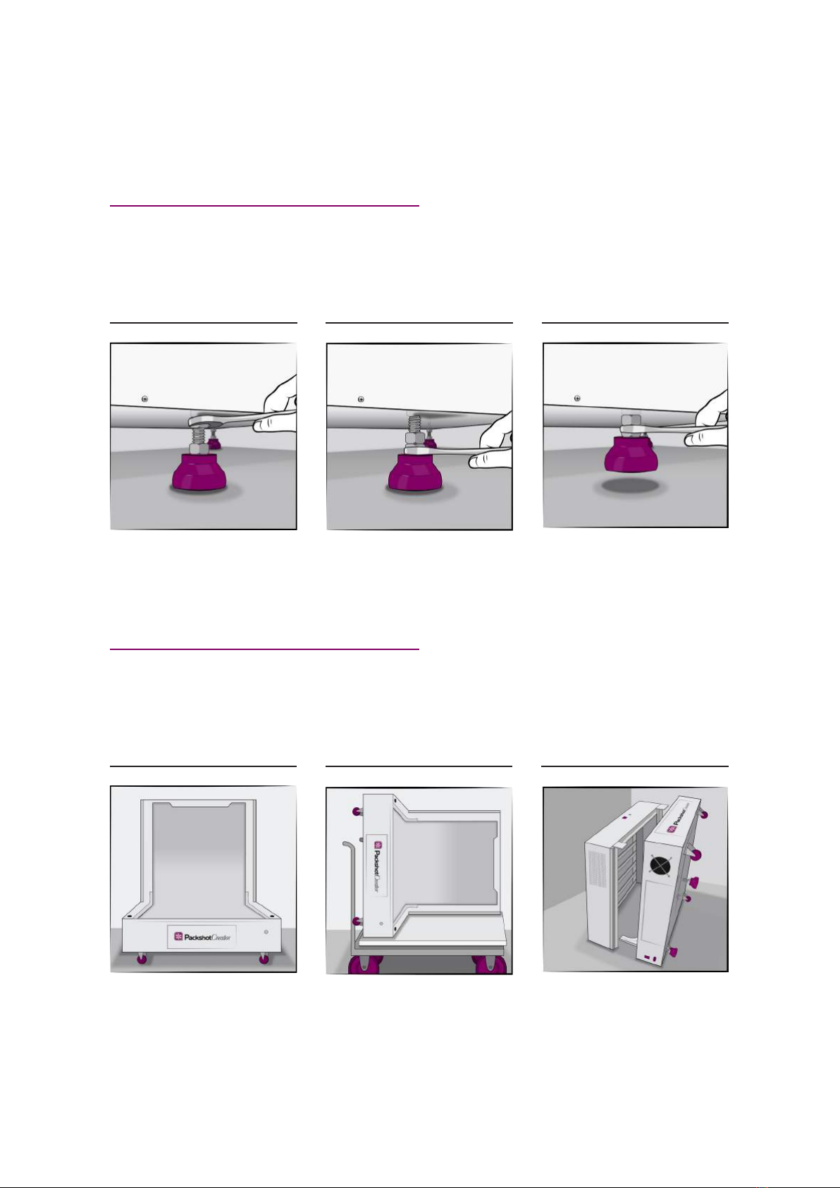
ROLLING THE UNIT:
01 02 03
Use the #24 wrench to adjust leg
height. Start by loosening the top
nut.
Rotate the bottom nut to raise or
lower the leg.
When all legs are up, roll the unit
into position. Lower the legs,
balance the unit, then re-tighten
the top nut against the bottom of
the unit.
GUIDING THE UNIT THROUGH A DOORWAY:
01 02 03
If the doorway is less than
114 cm wide, you will need to
remove the top, two side walls,
acrylic panels if any, front door and
two front light columns to get the
unit through the door. See detailed
disassembly. instructions in the
“Hardware Disassembly” part of
this document.
Get a dolly. Place a piece of foam
on top. Place the system on its
side on the dolly / foam. Lift and
guide / curve the unit through the
doorway.
(Optional): You can further
separate the back and bottom light
panels to get the unit through the
doorway more easily. See detailed
disassembly instructions in the
“Curved Background Removal”
and “Back and Bottom Light Panels
Separation” of the “Hardware
Disassembly” part of this
document.

PackshotCompact
SYSTEM PLACEMENT
PLACEMENT:
01 02 03
Place the system on the oor. Make
sure the system is level and legs
are locked into position.
(Optional): Place the system on
an PackshotCreator ErgoTable (sold
separately).
(Optional): Place the system on
an PackshotCreator ErgoTable+
(sold separately).
(Optional): Place the system on
an PackshotCreator Supporting
Box (sold separately).
Any external lighting, such as
PackshotCreator LiveStudio light,
can be used with the system when
some or all of the top, two side
walls, acrylic panels, front door
and two front light columns are
removed.
04 05
PackshotCompact
HARDWARE INSTALLATION
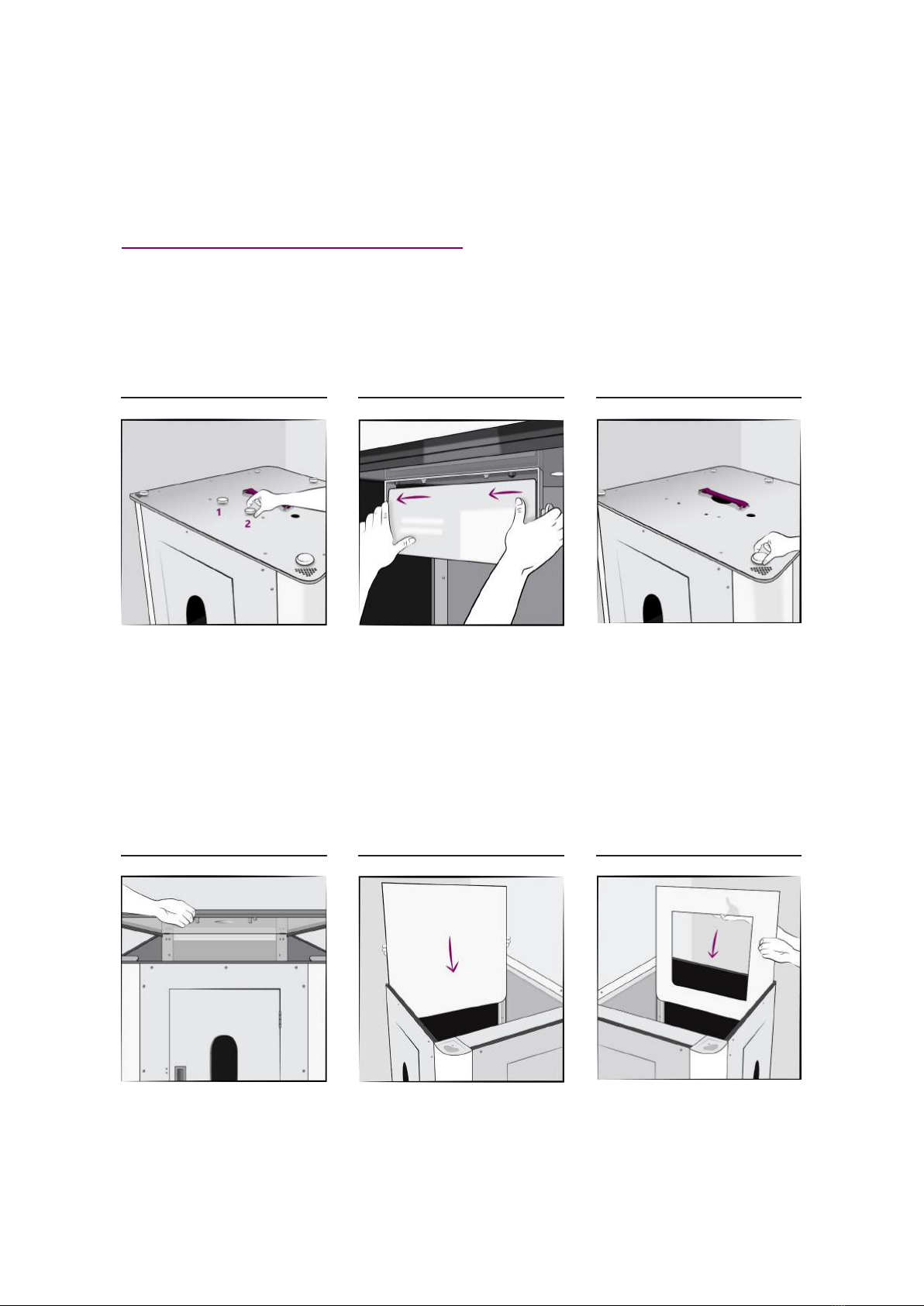
ACRYLIC PANEL INSTALLATION 1/2:
01 02 03
Remove the two white hand screws
holding the top light panel to the
top.
Remove the top light panel from
the top by sliding it to the left and
take it off with caution.
Remove the ve white hand
screws.
Remove the top. Three acrylic panels come with the
system - one solid, one with an
opening at center and one with
a small hole at bottom. Choose
which two panels to use.
Place the one with an opening
on either side for convenient side
loading. Slide the panels in from
the top through the two guide
notches / cut outs in the holding
bracket and front door.
04 05 06
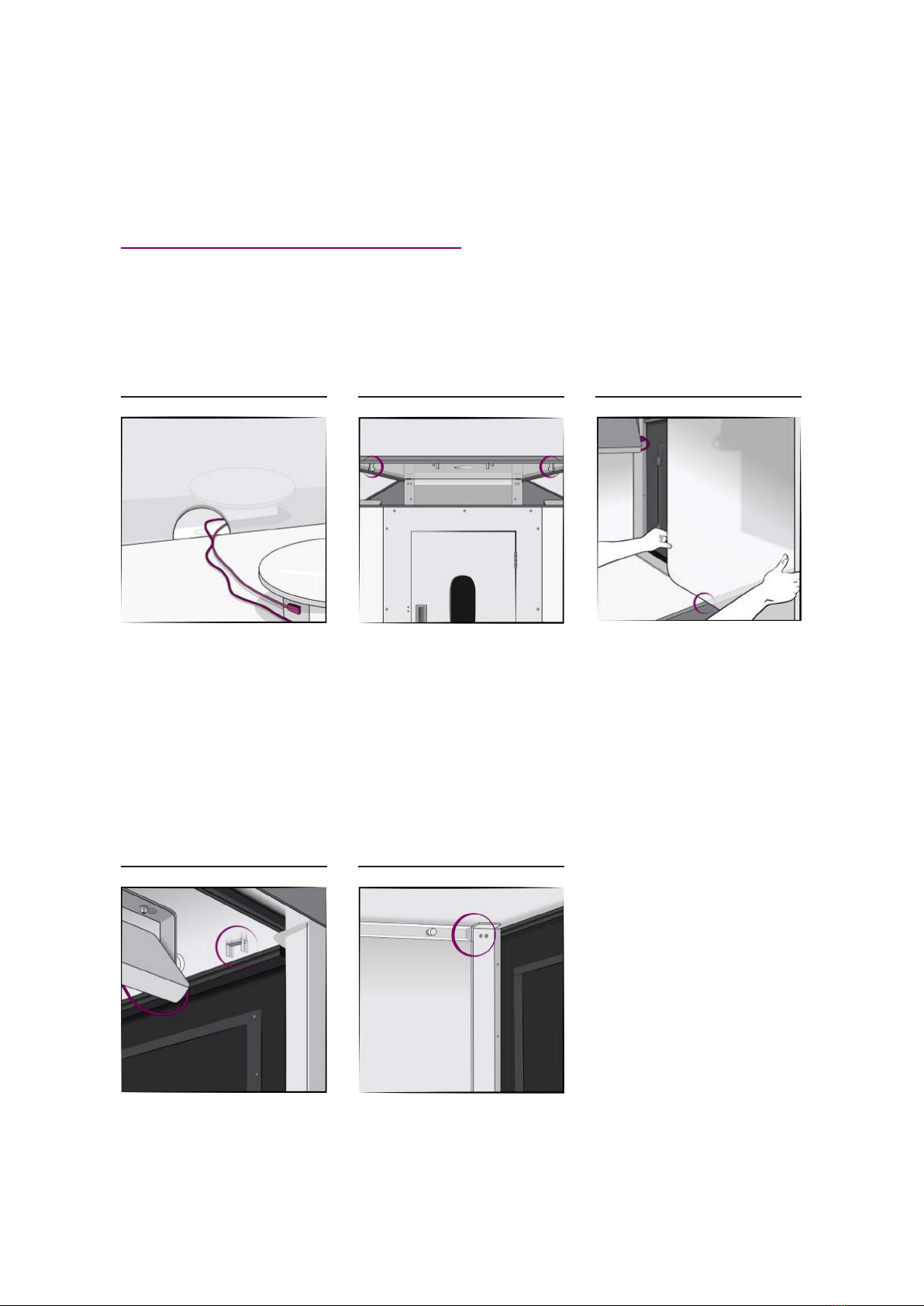
Note: Place the acrylic panel with
a small hole at bottom on the left
side when using a PackshotSpin
O3T inside the PackshotCompact,
so the power and USB cables can
be strung through the small hole
and then pluged into the power
jack and USB port on the frame of
the bottom light panel respectively.
Reverse steps 01 to 04 to replace
the top and top light.
Note: Align the acrylic panels
between the metal guide brackets
on the top, before tightening.
(Optional): The acrylic panels can
also be installed through the front
when the front door is detached.
Insert the acrylic panels between
the guide notch on the bottom.
07 08 09
PackshotCompact
HARDWARE INSTALLATION
ACRYLIC PANEL INSTALLATION 2/2:
Respectively insert the acrylic
panels between the metal guide
bracket on the top.
Finally slide the rest of the panel
into the guide notch on the back
wall holding bracket.
10 11
PackshotCompact
HARDWARE INSTALLATION
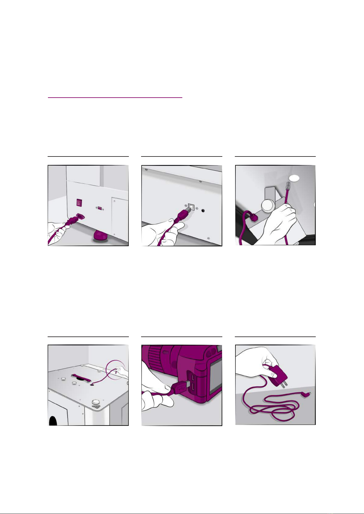
CABLE CONNECTION 1/2:
01 02 03
Plug one end of the power cable
into the system and the other end
into a power socket.
Plug one end of USB Type B cable
into the system and the other end
into a computer USB port.
String the top light power cable
through the ceiling hole.
Plug it into the port on the top
of the back light panel. Rotate
clockwise to tighten.
Connect a compatible camera to
your computer by USB.
(Optional): Instead of batteries,
we recommend using an AC power
adapter to power your camera.
(Optional Connections): For
almost all SLR cameras featuring
remote capture capabilities,
PackshotCompact can supply a
custom shutter release cable to
connect the camera to the system
so software can automate image
capture.
04 05 06
PackshotCompact
HARDWARE INSTALLATION
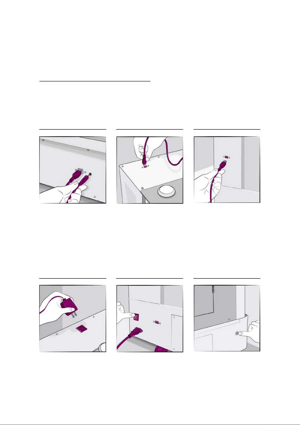
CABLE CONNECTION 2/2:
07 08 09
In this conguration, captured
images are saved to the memory
card.
If you are using camera top shot,
plug the USB cable from your
camera to your computer directly,
or into the USB port on the top of
the back light panel rst.
Respectively, plug one end of the
USB Type A cable into the left side
of the back light panel and the
other end into your computer USB
port.
(Optional): If you are using AC
power adapter, plug it into the
power socket on the top of the
back light panel.
Flip the system power switch on. Press the metal button switch to
turn on the system.
10 11 12
PackshotCompact
HARDWARE DISASSEMBLY
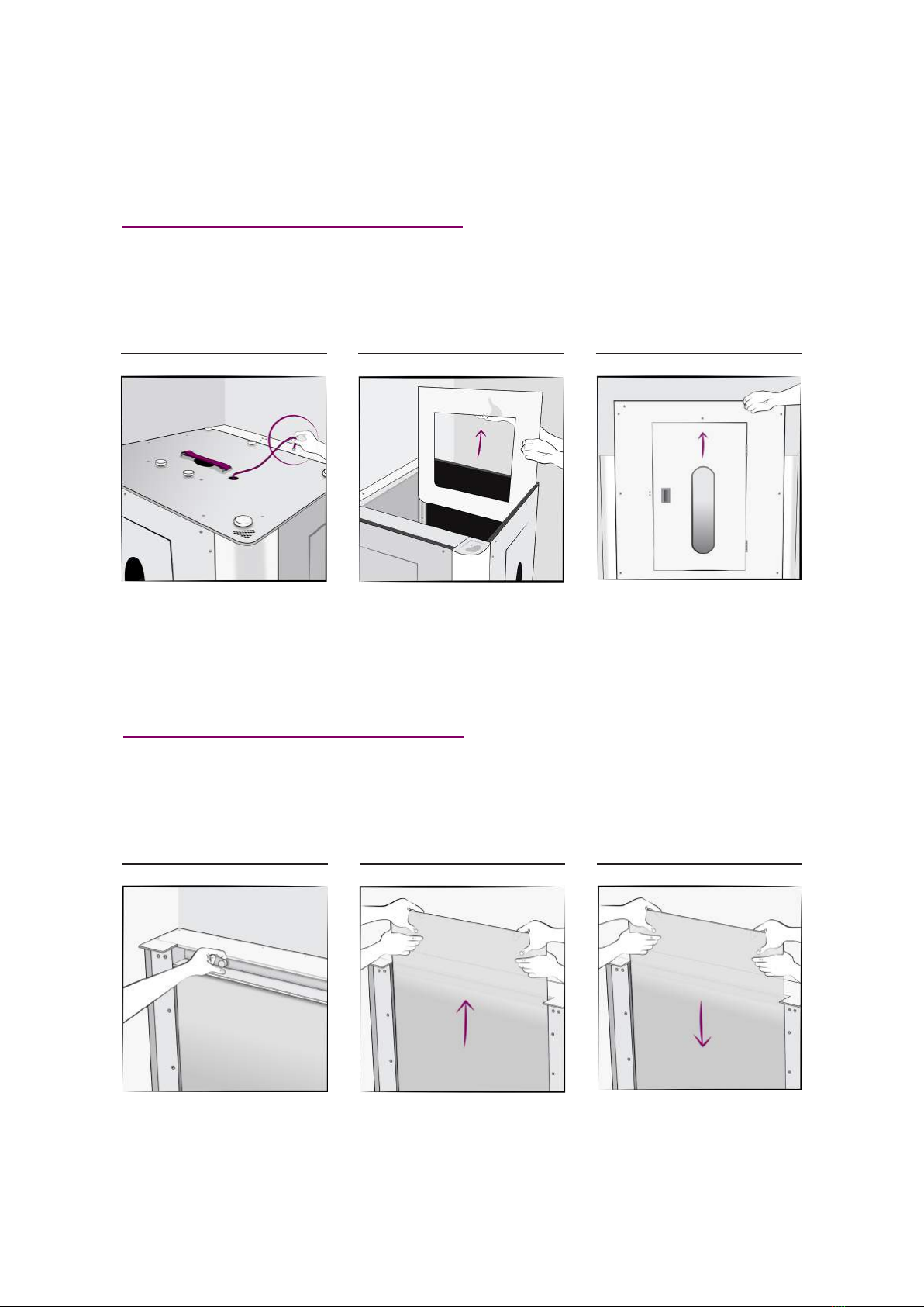
SURROUNDING COVERS REMOVAL:
01 02 03
Unplug the studio and the top light
power cable.
Follow instructions from steps
01 to 04 in the “Acrylic Panel
Installation” part of this document
to remove the top and top light,
and then remove the acrylic panels
if any.
Lift to remove both side walls and
front door.
CURVED BACKGROUND REMOVAL:
01 02 03
Remove two small white hand
screws and the holding bracket on
the top of the curved background.
Lift to remove the curved
background from the system with
two people at opposite sides.
Note: When re-installing
the curved background, we
recommend to slide it down with
two people at opposite sides. Use
one hand to brace and guide the
bottom corner into the curved rail
and then press it down until it ush
with the bottom background.
Table of contents
Other PackshotCreator Digital Imaging Accessories manuals


