PackshotCreator R3 Mark II
SYSTEM PLACEMENT
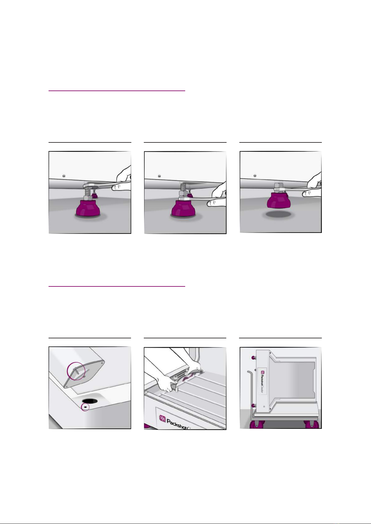
ROLLING THE UNIT:
01 02 03
Use the #24 wrench to adjust leg
height. Start by loosening the top
nut.
Rotate the bottom nut to raise or
lower the leg.
When all legs are up, roll the unit
into position. Lower the legs,
balance the unit, then re-tighten
the top nut against the bottom of
the unit.
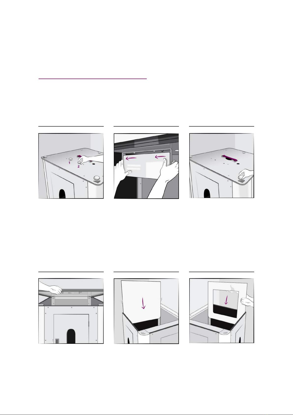
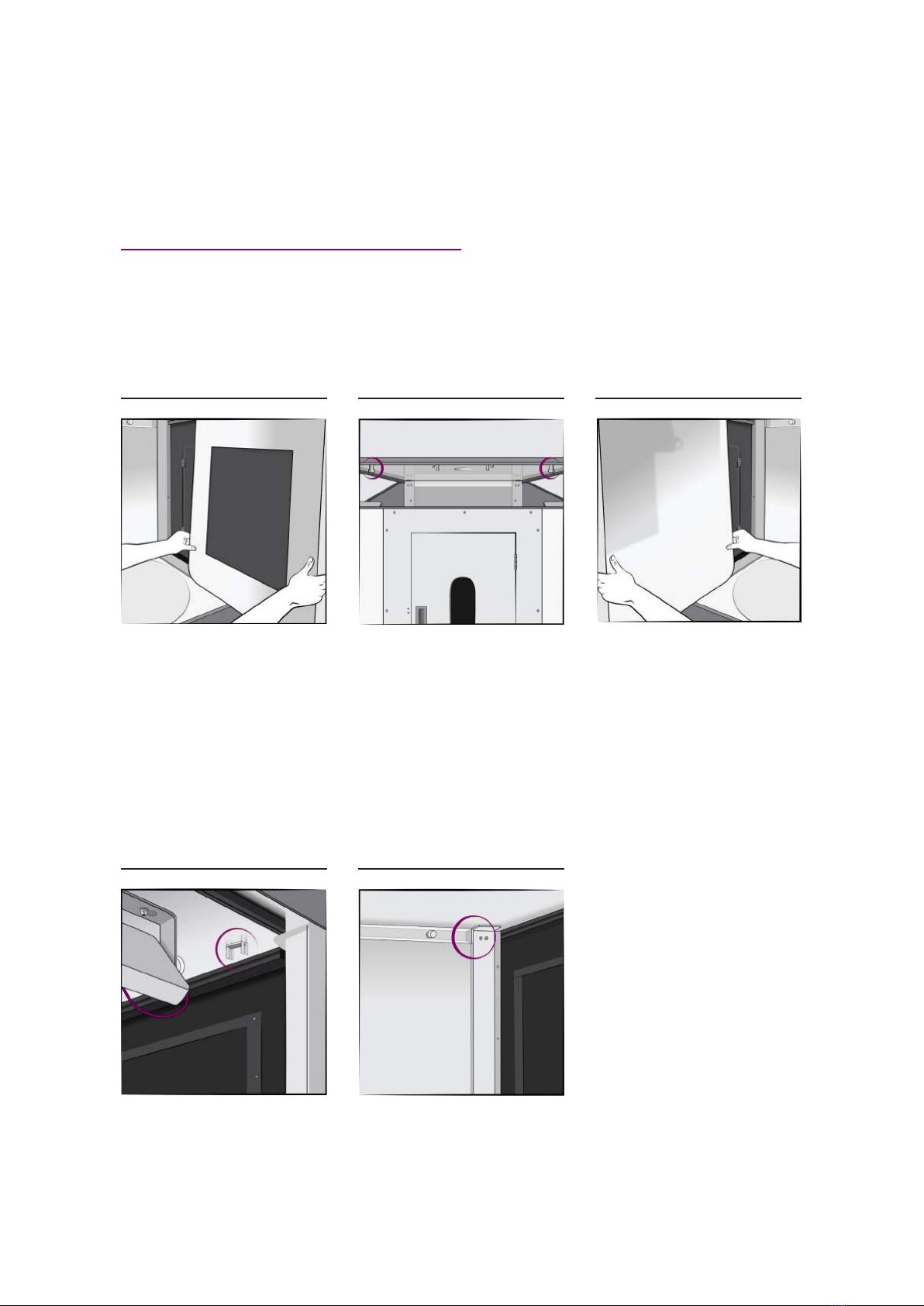
GUIDING THE UNIT THROUGH A DOORWAY:
01 02 03
If the doorway is less than 115cm
wide, you will need to remove the
top, two side walls, acrylic panels,
front door, two front columns,
translucent turntable platform,
glass turntable, and motor to get
the unit through the door. See the
“Component Replacement” of this
document.
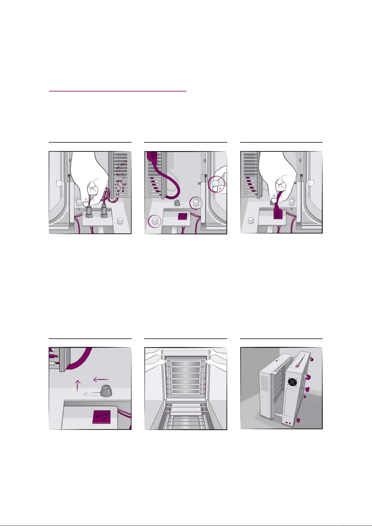
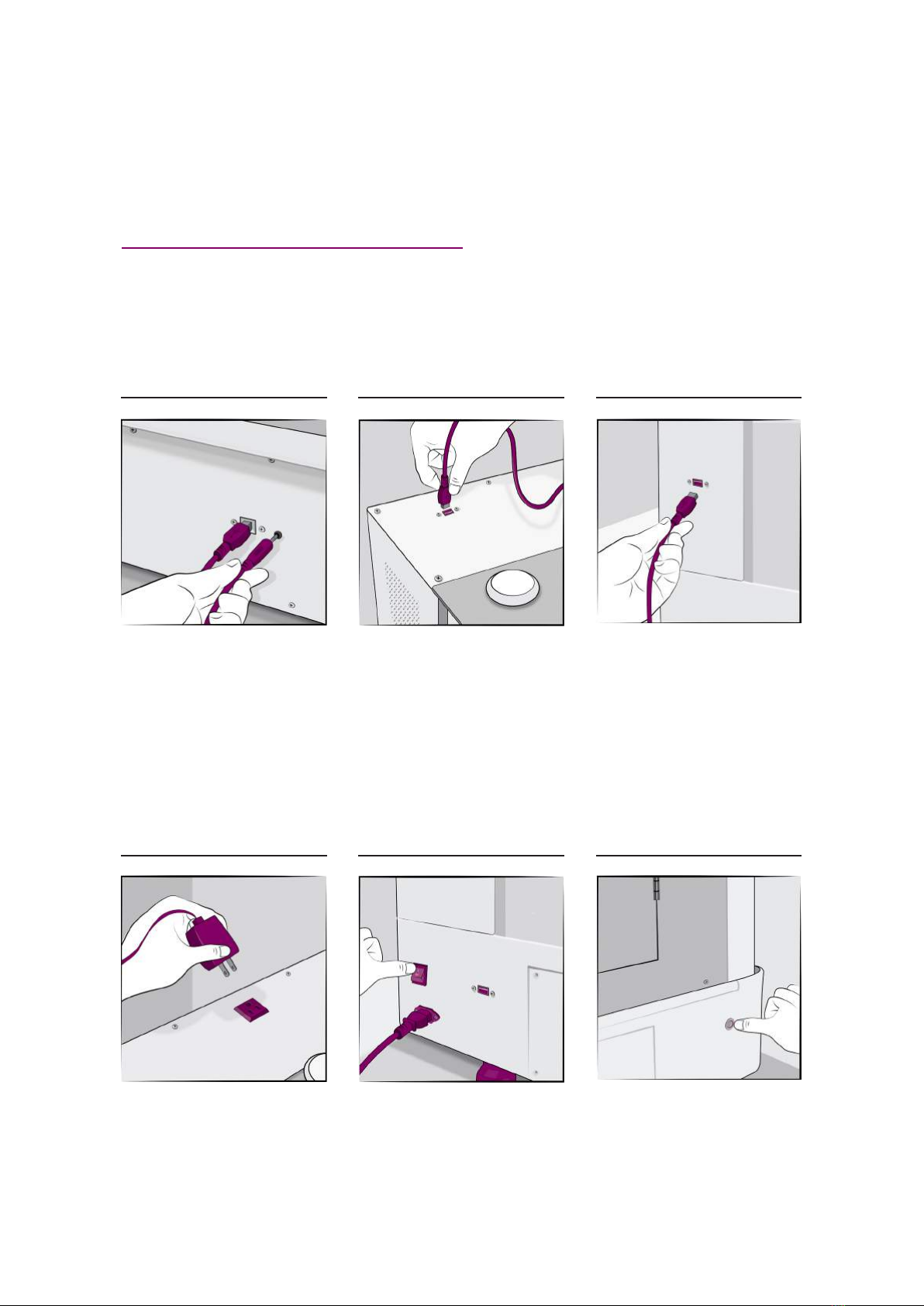
Slide the motor out from the rail
and unplug the signal cable.
Get a dolly. Place a piece of foam
on top. Place the system on its
side on the dolly / foam. Lift and
guide / curve the unit through the
doorway.