PAG PAGlink 9707A User manual

PL16 & PL16+ Chargers
User Guide
U5115

PAG Ltd.
565 Kingston Road
London SW20 8SA
United Kingdom
T: +44 (0)20 8543 3131
www.paguk.com
Disclaimer
The information contained in this document is correct at the
time of publication. PAG Ltd. reserves the right to change
specifications or product details without notification. Changes
to product details will be incorporated in the next version of
the document. PAG updates documents on a regular basis.
Trademarks
All PAG registered trademarks are the property of PAG Ltd.
All third party trademarks are acknowledged as such.
Copyright © 2019 PAG Ltd. All rights reserved

3
Section Page
1 Key Features 4
2 Safety Information 5
3 Specifications 7
4 Operating Instructions 9
5 Servicing 11
6 Guarantee 12
Contents
Thank you for choosing the PAGlink PL16 Charger.
Please read the important safety information and
instructions before using your charger.

Camera PSU
Power Button
LCD Screen (which indicates
charger functions for each
channel)
Camera PSU
XLR4 Output
AC Power
Input Socket
V-Mount Battery Connector Channel 1 V-Mount Battery Connector Channel 2
Camera PSU
Power Indicator
1. Key Features
4
The charger shown is:
Model 9707 PL16 Charger
• 2 x V-Mount battery connectors
• Camera Power Supply
Other models feature the following
variations:
Model 9707A PL16 Charger
• 2 x Gold Mount battery connectors
• Camera Power Supply
Model 9711 PL16+ Charger
• 4 x V-Mount battery connectors
Model 9711A PL16+ Charger
• 4 x Gold-Mount battery connectors
Patents Apply: paguk.com/patents

2.8 WARNING: This appliance must be earthed.
2.9 Users who are not qualified electronics technicians must not attempt
to disassemble the charger. There are no user-serviceable parts inside,
and incorrect reassembly may result in a safety hazard.
2.10 Do not use the charger if it has been damaged in any way, for
example: the supply cord or plug is damaged; liquid has entered the
casing; it has been exposed to rain or moisture; it does not operate
normally or it has been dropped. In these circumstances, seek advice
from your nearest authorised PAG Service Centre, or direct from PAG
UK, by telephoning +44 (0)20 8543 3131, or emailing
2.1 This booklet contains important safety and operating instructions.
Please read it fully and note all warnings before using the charger.
Please follow all instructions and retain this manual for future
reference.
2.2 PAGlink PL16 & PL16+ chargers are not intended for any use other
than the charging of batteries as detailed in Section 3 Specifications.
2.3 IMPORTANT: Use only on AC supplies 100-265V, 50/60Hz. Supply
connection to the unit should be made using only the standard lead
supplied with this equipment.
2.4 Protect the power cord from being walked on or pinched, particularly at
plugs. Unplug this apparatus during lightning storms or when unused
for long periods of time.
2.5 Ensure that the ventilation slots are not obstructed when in use, e.g.
do not site the charger on a carpet, and ensure that nothing covers
the charger when it is in use.
2.6 WARNING: Indoor use only. To reduce the risk of fire or electric shock,
do not expose this apparatus to rain or moisture.
2.7 Although the charger is short circuit protected, extreme care should
always be taken not to short circuit the battery itself. Rechargeable
batteries can deliver power at a very high rate, and short circuiting
even a partially charged battery could result in a fire or personal
injury.
2. Safety Information
5

3. Specifications
3.1 Chargers covered by these instructions:
9707 PAGlink PL16 V-Mount 2 charging positions
9707A PAGlink PL16 Gold Mount 2 charging positions
9711 PAGlink PL16+ V-Mount 4 charging positions
9711A PAGlink PL16+ Gold Mount 4 charging positions
3.2 Range of Batteries Charged:
9707 PL16 & 9711 PL16+ V-Mount Chargers:
• Parallel charging, individually or linked:
PAGlink PL96 Batteries (Models 9303 & 9304)
PAGlink PL150 Batteries (Models 9308 & 9309)
• Parallel charging, individually:
PAG L90 Slim Battery (Model 9307V)
PAG L95e, L96e & L96T Batteries (Models 9310V & 9305V)
Sony V-Mount Li-Ion Batteries
• Sequential charging, individually:
PAG L95 Model 9360, PAG L110 Model 9302V & PAG ZL-50 Model
9315V
• Individual charging:
PAG ZL-150 Model 9316V & PAG ZL-125 Model 9317V
9707A PL16 & 9711A PL16+ Gold Mount Chargers:
• Parallel charging, individually or linked:
PAGlink PL94 Batteries (Model 9306)
PAGlink PL150 Batteries (Model 9313)
Mini PAGlink MPL50 Batteries (Model 7141)
Mini PAGlink MPL99 Batteries (Model 7241)
• Parallel charging, individually:
PAG L96 Batteries (Models 9310A & 9305A)
3.3 Main Charge Programs:
Li-Ion Intelligent Parallel Charging program: maximum output 6A at
16.8V (100W approx.). V-Mount Models only: PAG ACS Ni-MH sequential
charge program, output 3A.
3.4 PAGlink Charging:
Up to 8 PAGlink batteries can be charged on each position. Batteries
can be of any rated capacity and in any state of charge. The most
discharged batteries will be given priority. Fully charged batteries
stop accepting charge automatically and independently. Batteries may
be left on the charger when fully-charged and will be maintained in a
ready-for-use condition.
3.5 Recovery Charge Program:
A battery that will not accept charge, and is indicated as ABST on the
charger display, can be given a Recovery Charge, initiated by two
presses of the front panel button on PL16 Chargers (Models 9707 &
9707A). Normal charging will follow after a few seconds. Recovery
6

3. Specifications
Charge will be applied automatically in the case of PL16+ chargers
(Models 9711 & 9711A). Additionally, all chargers will recover automati-
cally a Li-Ion battery where the output has been shut down.
3.6 Self Test Program:
The internal microcomputer constantly monitors the battery under
charge, as well as the operation of the charger’s own functions, which
will be shut down to a safe condition should any of the tests fail.
3.7 Mains Input:
100V to 265V AC. Frequency 50-60 Hz. Maximum consumption 220W.
3.8 Output Protection:
The charger is protected against short circuit and excess battery
voltage.
3.9 AC Mains Failure Protection:
Should mains failure occur during a charging program, or whilst the
charger is connected, it will shut down to a safe condition.
3.10 User Interface:
The charge status of each PAGlink battery is indicated by its own
display. The different stages of the charging process are indicated for
each channel on the charger’s LCD screen. The charger is fully
automatic in operation.
3.11 Safety:
Designed to comply with electrical safety standard BS EN 60065 and
UL1564. NOTE: UK AC power leads are fitted with a 1" fuse to BS1362
rated 5A.
3.12 European Union Directives:
Complies with the following EU Directives:
EMC Directive 2004/108/EC.
Low Voltage Directive 2014/35/EU.
3.13 Operating Temperature Range:
0ºC to +40ºC (+32ºF to +104ºF).
3.14 Overall Dimensions & Weight:
9707 PL16 V-Mount:
H 75mm (3.0”) W 210mm (8.3”) D 190mm (7.5”) 1.4kg (3lbs).
9707A PL16 Gold Mount:
H 75mm (3.0”) W 220mm (8.6”) D 190mm (7.5”) 1.4kg (3lbs).
9711 PL16+ V-Mount:
H 75mm (3.0”) W 217mm (8.5”) D 315mm (12.4”) 1.6kg (3.5lbs).
9711A PL16+ Gold Mount:
H 75mm (3.0”) W 217mm (8.5”) D 315mm (12.4”) 1.6kg (3.5lbs).
7

3. Specifications
process. Customers can remove the battery at 90% charged to reduce
the overall charge time significantly.
3.16 Camera Power Supply (Models 9707 & 9707A only):
Suitable for powering cameras that can accept a 16.8V input.
3.17 Operation:
The camera power supply function is operated by pressing and
holding the Camera PSU button on the charger’s front panel for 1
second. Charging is suspended whilst the power supply is in use.
3.18 Output:
16.8V DC. Maximum current 5.5A (90W).
3.19 Output Connector:
XLR4F connector (Pin 1 Neg, Pin 4 Pos).
3.15 Typical Battery Charging Times:
The charge times given are for 96Wh PAGlink batteries, from fully-
discharged to fully-charged. Charge times will be less if the batteries
are only partially discharged, and will vary depending on the condition
of the batteries. Charge times for 150Wh batteries will be approxi-
mately 50% longer.
Total: Configuration: Time:
1 2 hrs 30 mins
2 (1 / 1) 3 hrs
4 (2 / 2) or (1 / 1 / 1 / 1) 6 hrs
6 (3 / 3) or (2 / 2 / 1 / 1) 9 hrs 30 mins
8 (4 / 4) or (2 / 2 / 2 / 2) 11 hrs 45 mins
16 (8 / 8) or (4 / 4 / 4 / 4) 24 hrs
32 (8 / 8 / 8 / 8) 48 hrs
The current is shared between charging channels. To fast-charge an
individual battery in the fastest time it is best to connect only that
battery to the charger.
As Li-Ion batteries near full charge, the charge current is reduced.
The final 10% therefore takes longer than at any other stage of the
8

4. Operating Instructions
4.1 PAGlink PL16 Chargers are fitted with an AC input socket conforming
to CEE22 (IEC socket). AC supply connection to the charger should be
made using only the standard lead supplied with this equipment.
4.2 PAGlink PL16 Chargers have been designed for use on AC supplies
worldwide, and automatically accept supplies in the range 100V to
265V. AC supply frequency must be in the range 50-60Hz.
4.3 IMPORTANT: Note Section 4.17 Supply Failure. PAGlink PL16 Chargers
may be disconnected from the supply at any time in complete safety
and without damage to the charger or any batteries connected.
4.4 Connect the charger to a suitable supply using the standard lead.
The red LCD screen will illuminate and display the software version.
4.5 On power-up, the charger will automatically run a self test program.
4.6 With no batteries connected, the display will indicate ‘ABST’ on each
channel:
PL16 Display PL16+ Display
4.7 Before connecting a battery to the charger ensure that the battery is
not in Sleep Mode by pressing the battery display button twice, so
that the battery display illuminates.
When batteries are connected, charging will commence automatically
and the charger display will indicate ‘CHRG’ on the appropriate
channels:
PL16 Display PL16+ Display
4.8 Up to 8 PAGlink Batteries per channel may be charged. Batteries can
be of any rated capacity and in any state of charge. The charge status
of each PAGlink battery is indicated by its own display. The most-
discharged batteries will be given priority until all the batteries are in
a similar state of charge. The batteries will then fully-charge
simultaneously, making the most efficient use of the current
available. Fully-charged batteries stop accepting charge automatically
and independently of other batteries. Fully-charged batteries can be
left connected to the charger until they are needed.
4.9 The charger display will indicate ‘DONE’ when all the batteries
connected to that channel have received as much charge as they can
safely accept:
PL16 Display PL16+ Display
9

4. Operating Instructions
4.10 As Li-Ion batteries near the end of charge, the charge current is
reduced. This is perfectly normal for the ‘constant voltage’ phase of
the charge cycle.
4.11 Batteries may be removed, and others connected at any time, without
affecting the operation of the charger.
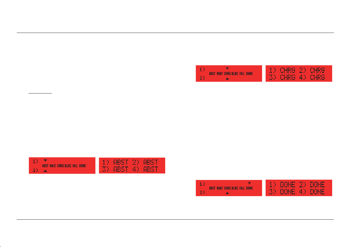
4.12 The charger will continue to monitor the status of all charging
channels. It will not attempt to charge batteries which the charger
indicates are ‘DONE’ or faulty (indicated as ‘FAIL’). When there are no
batteries connected the charger display will indicate ‘ABST’:
PL16 Display PL16+ Display
If a new battery is connected to the free channel, the charging
sequence will be initiated automatically. The order in which batteries
are connected is therefore immaterial; the charger will ensure that all
batteries are charged in as short a time as possible.
4.13 If the charger detects a faulty battery while the charging program is
running, the display will show ‘FAIL’. This could be caused by one of
several conditions, such as a very old or damaged battery, a short
circuit battery, or an excessively high or low voltage battery.
4.14 The charger will not recognise the connection of a battery which has
a voltage substantially outside of its range or one of unsuitable
chemistry type.
4.15 If the internal protection circuit of a PAG or Sony Li-Ion battery
should turn-off, for any reason, the battery display will not operate,
and there will be no voltage at the battery terminals. The PL16
incorporates a Recovery Charge program which will automatically turn
the protection circuit back on again.
4.16 If the charger should detect a fault during operation, it will shut
down to a safe condition. See Section 5.4 ‘Servicing’.
4.17 If the AC mains power fails during operation, the charger will shut-
down safely; no damage will occur to either the charger or the
batteries. When the mains power is restored the charger will default
to the main charge program.
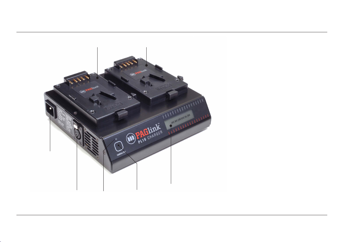
4.18 PL16 Chargers, Models 9707 & 9707A, feature a built-in Camera
Power Supply that enables you to power your camera from an AC
mains supply, using the charger. Connection to the camera can be
made using an XLR4 male to female lead (PAG Model 9450). The
power supply is operated by pressing the button on the front panel
of the charger, and holding it in for 1 second. The blue LED above the
button will light to indicate the power supply is in operation. When
the camera power supply is in use, charging is suspended.
10

5. Servicing
5.1 WARNING: To reduce the risk of electric shock, do not attempt any
servicing or repairs unless you are qualified to do so. Refer all
servicing or repairs to qualified servicing personnel. The charger
contains advanced electronics that do not require periodic mainte-
nance. Consequently there are no user-serviceable parts inside.
5.2 Qualified electronics engineers who wish to gain access to internal
assemblies should note that parts of the power circuit retain a high
voltage even after the power supply has been disconnected. Wait for a
period of five minutes following disconnection before commencing
disassembly, and be aware of charged capacitors.
5.3 When the charger is correctly connected to an AC supply and the
display is not functioning, it may be that a supply fuse has become
open circuit. Equipment for use in the UK is supplied with a standard
AC power lead, complete with a moulded, fused plug. If this fuse has
become open circuit it should be replaced by another of the correct
rating (see Specification Section 3.11). USE ONLY A FUSE OF THE
CORRECT RATING. If the replacement of the fuse fails to correct the
above symptoms, do not attempt further fuse replacement, it is likely
that a fault has developed. Contact your nearest authorised PAG
Service Centre:
The Americas:
PAG America, 18 Center Street, Ramsey, NJ 07446, USA
Europe & Middle East:
Aspectra BV, Spoorhaven 78, 2651 AV, Berkel en Rodenrijs, Netherlands
United Kingdom and Rest of the World:
PAG Ltd. 565 Kingston Road, London SW20 8SA
5.4 The chargers feature a fail-safe shutdown mode. In the unlikely event
of an internal malfunction, an error message will be displayed on the
screen. This could be the result of any number of undesirable
situations from which the system is protecting itself, such as the
obstruction of ventilation slots, causing inadequate cooling, or the
microcomputer’s detection of an internal fault. In these cases the
charger should be disconnected from the supply, any obstruction of
the air vent system removed, and the unit allowed to cool before
reconnecting to the supply. Should the charger re-enter the fail-safe
shutdown mode, more detailed investigation is required. Make a note
of the error message and seek advice from your nearest authorsied PAG
Service Centre.
5.5 Unqualified personnel should not attempt further investigation (see
paragraph 5.1 above). Any such interference would invalidate the
guarantee and could cause more damage than the original fault.
5.6 For technical information contact an authorised PAG Service Centre.
11

6. Guarantee
6.1 Notwithstanding any provision of any agreement the following
guarantee is exclusive: PAG Limited guarantees each PAGlink PL16
charger it manufactures to be free of defects in material and workman-
ship under use and service for TWO YEARS from the date of purchase.
This guarantee extends only to the original purchaser. This guarantee
shall not apply to fuses or any product or parts which have been
subject to misuse, neglect, accident or abnormal conditions of
operation.
6.2 In the event of failure of a product covered by this guarantee, PAG
Limited will repair and calibrate equipment returned to an authorised
service facility within the period of the guarantee, provided the
guarantor’s examination discloses to its satisfaction the product was
defective. The guarantor may, at its option, replace the product in lieu
of repair. With regard to any equipment returned within this period,
said repairs or replacements will be made without charge. If the failure
has been caused by misuse, neglect, accident or abnormal conditions
of operation, repairs will be billed at a nominal cost. In such a case,
an estimate will be submitted before work is started, if requested.
6.3 The foregoing guarantee is in lieu of all other guarantees, express or
implied, including but not limited to any implied guarantee or
merchantability, fitness or adequacy for any particular purpose or use.
PAG Limited shall not be liable for any special, incidental, or conse-
quential damages, whether in contract, tort, or otherwise.
12
This manual suits for next models
4
Table of contents
Popular Accessories manuals by other brands

Balluff
Balluff Micropulse BTL5 Series Technical Description, User's Guide

Tejovat Smart Home Products
Tejovat Smart Home Products TJ-SH-DP1500 user manual

Stobag
Stobag Airomatic PS 4000 quick start guide

Rice Lake
Rice Lake Revolution 680 Synergy Plus Technical manual

Sennheiser
Sennheiser GZK 1011 manual

Obelink
Obelink LIVING PITCHING INSTRUCTION

Vmac
Vmac A700327 installation manual

Western Technology
Western Technology WT-GERM KILLER BODYLight 8910UVC Standard operating procedure

SONBEST
SONBEST SM1410C user manual

Chauvin Arnoux
Chauvin Arnoux MiniFlex MA110 user manual

Bozz
Bozz party cooler BWC10 instruction manual

ZEN AROME
ZEN AROME TULIPE instruction manual