TeraBee IND-TOF-1 User manual

Terabee IND-TOF-1
Connection to Personal Computer
(Guide)
Technical support: [email protected]
Sales and commercial support: [email protected]

Table of contents
Introduction 3
PC setup instructions 3
Hardware setup 3
Software setup 5
MODBUS Doctor software configuration 6
Basic sensor parameter configuration 7
Read distance data example 7
Switching between operating modes 8
Verify operating mode example 9
Copyright © Terabee 2019
Terabee, 90 Rue Henri Fabre
01630, St Genis-Pouilly, France (next to CERN)
2/9

1. Introduction
The purpose of this document is to give guidelines for connection and use of the
Terabee IND-TOF-1 distance sensor with a Personal Computer (PC).
2. PC setup instructions
The following section provides guidelines on connection and sensor evaluation on a PC,
using Microsoft®Windows®OS. This includes instructions on hardware arrangement,
software setup using MODBUS Doctor application (v2.7) and examples on executing
commands for modifying some of the basic sensor parameters.
IMPORTANT. Please note that standard RS485-to-USB converter and M12 Male-Female cable
are required for connecting and operating the Terabee IND-TOF-1 sensor with a PC. Please
find below links to reference components used for the purposes of this document:
●RS485-to-USB converter
●M12 Male-Female cable, 5pin
Table 1 - Connectors description
M12, 5-pin A-coded
connector (male)
D-Sub 09 PoS connector
(male)
USB type B connector
(male)
Copyright © Terabee 2019
Terabee, 90 Rue Henri Fabre
01630, St Genis-Pouilly, France (next to CERN)
3/9

2.1. Hardware setup
Figure 2 illustrates connection logic between the IND-TOF-1 sensor and a PC, and the
following components are required for a complete setup:
●Terabee IND-TOF-1 distance sensor
●Straight M12 5-pin A-coded cable of your preference (not provided by Terabee)
●RS485-to-USB adapter (not provided by Terabee)
●USB cable with Type B connector (not provided by Terabee)
●Control Unit (PC)
●Power Supply capable of supplying 24V DC @ 100mA
Figure 2. Sensor and PC hardware setup diagram
The following summarizes the steps to be taken for connecting the IND-TOF-1 sensor to
a PC.
Please note that there is some soldering involved, as the M12 connector is not directly
compatible with the D-Sub 09 PoS connector of the RS485-to-USB adapter.
Step 1
Connect the M12 cable to the sensors M12, 5-pin connector.
Step 2
Connect the data lines of the M12 cable to the D-Sub 09 PoS (DB9) male connector of
the RS485-to-USB adapter. See wiring instructions in table 2.
Table 2 - Wiring connection between IND-TOF-1 and D-Sub 09 PoS connector
Copyright © Terabee 2019
Terabee, 90 Rue Henri Fabre
01630, St Genis-Pouilly, France (next to CERN)
4/9

M12 cable
D-Sub 09 PoS connector
Tx/Rx+ (pin 4)
Pin 2
Tx/Rx- (pin 5)
Pin 1
Ground (pin 2)
Pin 5
Step 3
Connect the power lines of the M12 cable to a power supply source. See wiring
instructions in table 3. Wire +24V (pin) and GND (pin) to the selected power supply
(capable to provide 24V supply).
Table 3 - Wiring connection between IND-TOF-1 and Power supply
M12 cable
Power supply
+24V (pin 1)
Pin x
GND (pin 2)
Pin y
Step 4
By using a USB cable, connect the RS485-to-USB adapter to the USB port of your PC.
Please note that the USB cable must support connectivity with a Type B connector on
the adapter side, and a preferred connector on the users PC side (Type A, Type C, etc.)
Step 5
Power the sensor by turning on the power source.
Step 6
The sensors LED indicator PWR will now constantly stay ON (RED) to confirm proper
voltage supply.
Step 7
The hardware setup is completed and the user can now proceed to configuring basic
software parameters.
During power up the sensor will apply the last operating mode used or mode 1 (factory
default) if it is used for the first time
Note: The NO/NC line is not used in this setup, it can be left floating or shorted to ground
Copyright © Terabee 2019
Terabee, 90 Rue Henri Fabre
01630, St Genis-Pouilly, France (next to CERN)
5/9

2.2. Software setup
As the Terabee IND-TOF-1 sensor uses the MODBUS RTU protocol for data
communication via RS485 interface, for operation on PC we recommend to work with
MODBUS Doctor freeware utility software (KScada). To do so, please follow the link
below to the official page of KScada and download the MODBUS Doctor software.
Link to MODBUS Doctor download page: http://www.kscada.com/modbusdoctor.html
2.2.1. MODBUS Doctor software configuration
After successful download, initiate the software on your PC. Next, select RTU to make
sure the following settings are configured accordingly:
●Baud rate: 19200
●Data bits: 8
●Stop bits: 1
●Parity: even
●Port Name: select the USB port on which the RS485-to-USB adapter is connected
For visual instructions please consult Figure 3. Once these parameters are configured,
click “Connection”. Contact with the sensor should now be established and the Status
(bottom left) should change to “Connected”. Figure 4 illustrates a successful connection.
Figure 3. Setting connection parameters on MODBUS Doctor
Copyright © Terabee 2019
Terabee, 90 Rue Henri Fabre
01630, St Genis-Pouilly, France (next to CERN)
6/9

Figure 4. Status after pressing “Connection”
2.3. Basic sensor parameter configuration
To learn more about IND-TOF-1 operating modes and their setup and functionality,
please refer to the official product user manual.
To learn more about all configurable sensor parameters, please refer to the official
product user manual.
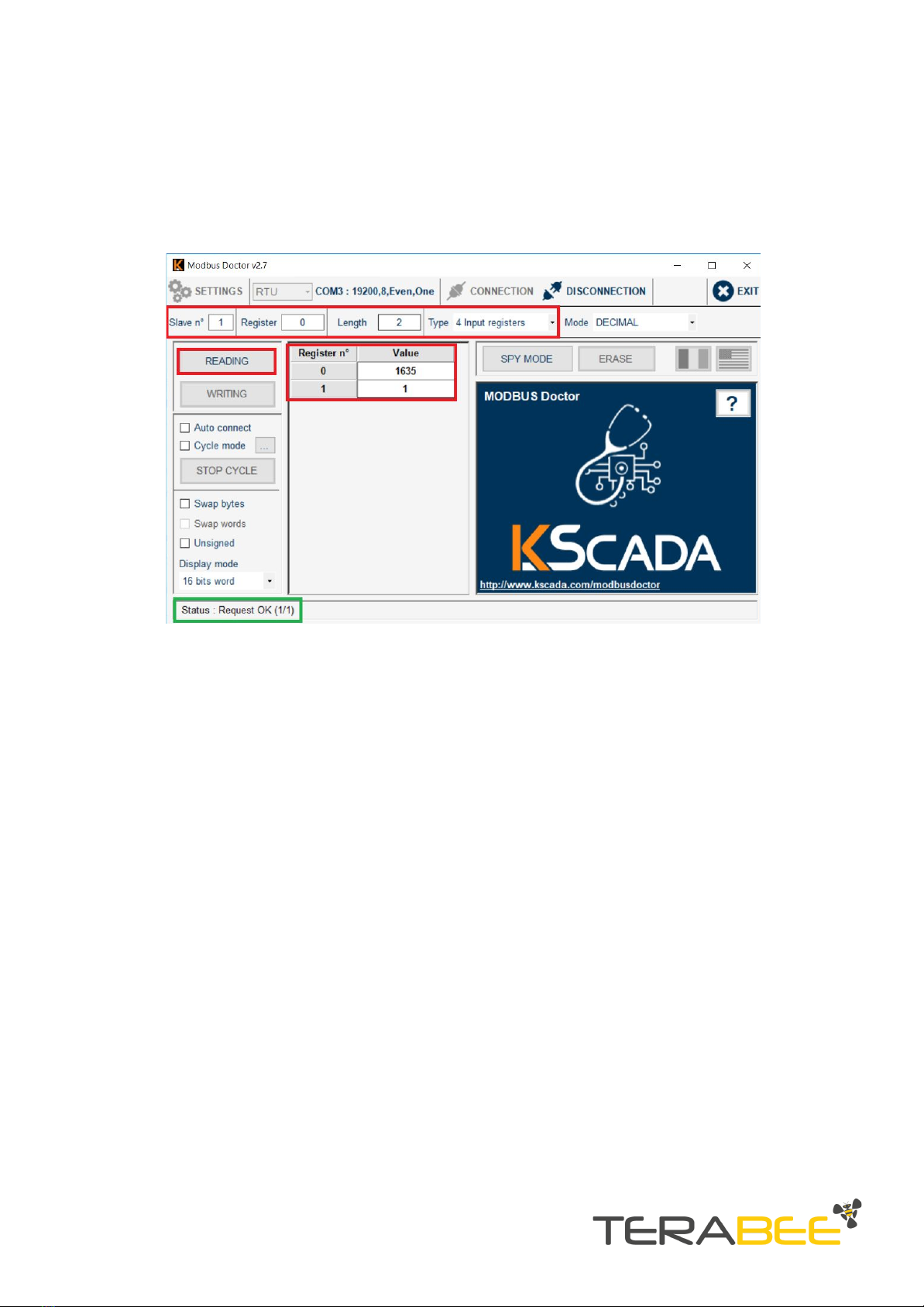
2.3.1. Read distance data example
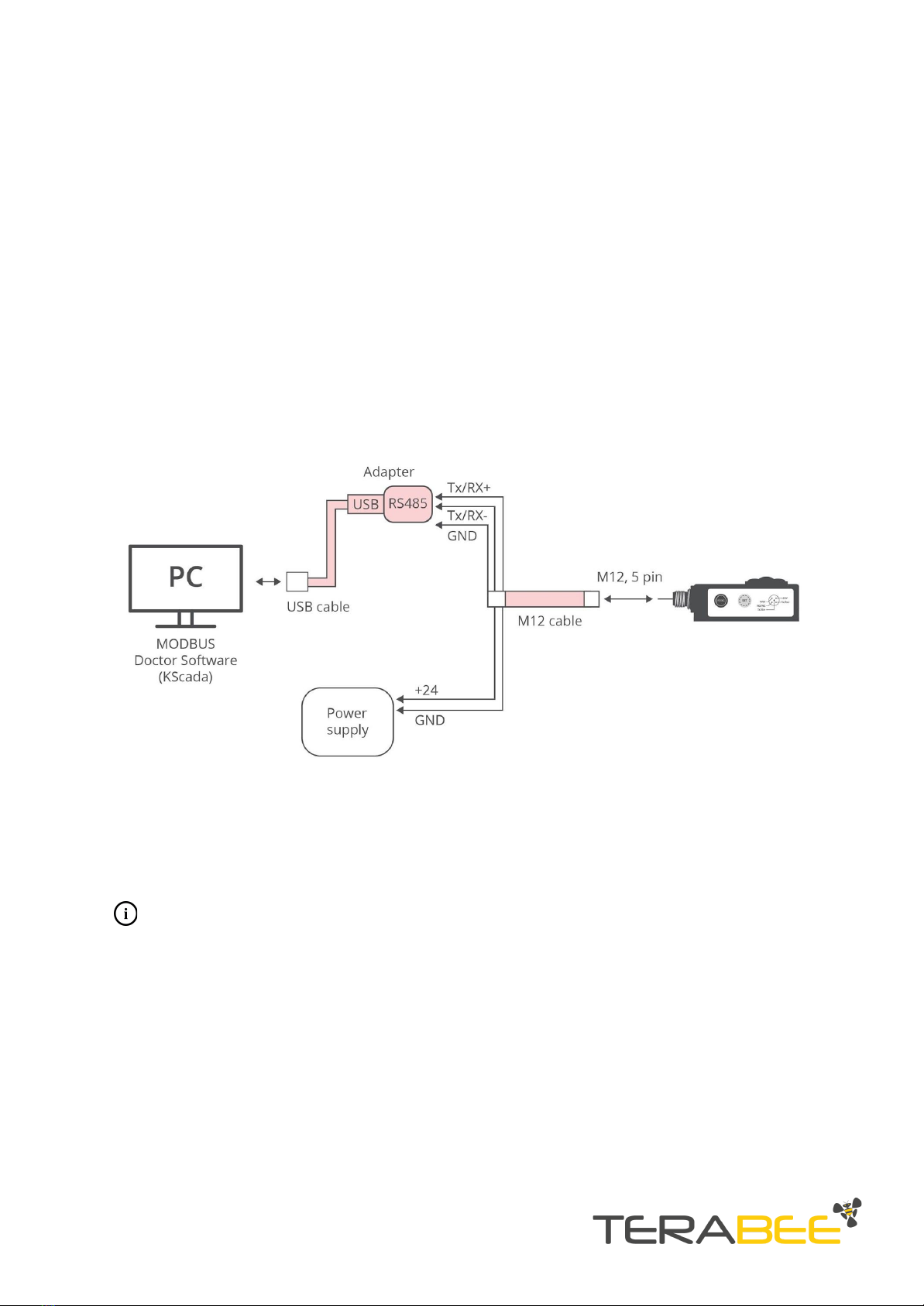
The MODBUS protocol uses a master/slave architecture of communication where one
device or process has unidirectional control over one or more devices. In order to read
(inquire) live distance data from the sensor, please execute the following READ
command:
Read distance data:
●Slave ID: 1 to 247 (enter corresponding slave ID, 1 in our case)
●Type (function): 04 Input Register
●Address location: 0
●Length (Quantity): 2
Click “READING” to execute command. The distance data is now read from the sensor,
and displayed in the “Value” field. During the data read, the sensors onboard LED
indicator (Sel) will blink BLUE to signal that the slave device (sensor) has been
Copyright © Terabee 2019
Terabee, 90 Rue Henri Fabre
01630, St Genis-Pouilly, France (next to CERN)
7/9

successfully selected by the master device, and the LED indicator (Tx) will blink RED, to
confirm successful data transmission via RS485. Visual instructions for executing “read
distance data” command are illustrated in Figure 5. The status indicator will also show
“Request OK (1/1)”.
Figure 5. Read distance data command execution example
2.3.2. Switching between operating modes
Terabee IND-TOF-1 provides users with 6 operating modes (learn more about each
mode functionality in the official user manual). By default the sensor is shipped with
operating mode 1 pre-set. To switch between operating modes, execute the following
WRITE command/s:
Write operating mode:
●Slave ID: 1 to 247
●Type (Function): 03 Input Register
●Register: 14
●Length: 1
●Value: 1 to 6 (1 for mode 1, 2 for mode 2 etc..)
Figure 6 illustrates an example for setting operating mode 2. In this case, input value 2
in the “Length” field and click “WRITING” to execute command.
The LED indicators (Tx; Sel) will blink RED and BLUE.
Copyright © Terabee 2019
Terabee, 90 Rue Henri Fabre
01630, St Genis-Pouilly, France (next to CERN)
8/9

Figure 6. Setting operating mode 1 (MODBUS)
2.3.3. Verify operating mode example
A quick READ command can be executed to verify that the new operating mode has
been successfully applied by the sensor.
Read operating mode:
●Slave ID: Slave ID: 1 to 247 (enter corresponding slave ID, 1 in our case)
●Type (Function): 03 Holding Register
●Register: 14
●Length: 1
Click “READING” to execute command. The LED indicators (Tx; Sel) will blink RED and
BLUE. Operating mode number is now displayed in the “Value” field.
Copyright © Terabee 2019
Terabee, 90 Rue Henri Fabre
01630, St Genis-Pouilly, France (next to CERN)
9/9
Other manuals for IND-TOF-1
3
Table of contents
Other TeraBee Accessories manuals

TeraBee
TeraBee ND-TOF-1 User manual

TeraBee
TeraBee TeraRanger One User manual

TeraBee
TeraBee TeraRanger Evo 64px User manual

TeraBee
TeraBee TeraRanger Evo Series User manual

TeraBee
TeraBee Follow-Me User manual

TeraBee
TeraBee TeraRanger Evo User manual

TeraBee
TeraBee TeraRanger Evo User manual

TeraBee
TeraBee TeraRanger Evo Thermal series User manual

TeraBee
TeraBee TeraRanger Evo User manual

TeraBee
TeraBee TeraRanger Neo ES User manual