Lippert Solera 5000 Series User manual

Solera®5000
Series Awning
OEM INSTALLATION MANUAL

Rev: 08.17.21 Page 2 CCD-0004406
TABLE OF CONTENTS
Introduction 2
Safety 2
Prior to Installation 3
Resources Required 3
Installation 3
Awning Rail Installation 3
Awning Installation 4
Securing the Fabric 6
Awning Wiring 6
Wiring Diagram 7
Installation with LED — Options 8
LED Light Rail Installation 8
LED Light Strip 8
Seal Wall Penetrations 9
Introduction
The Solera 5000 Series Awning features an easy access for manual overdrive and internal motor to steadily
operate the awning. Additionally, the pitch arm assembly allows for rain dump and adjustable pitch
features. The pitch arm assembly also provides added stability.
Safety
Read and understand all instructions before installing or operating this product. Adhere to all safety labels.
This manual provides general instructions. Many variables can change the circumstances of the instructions,
i.e., the degree of difficulty, operation and ability of the individual performing the instructions. This
manual cannot begin to plot out instructions for every possibility, but provides the general instructions,
as necessary, for effectively interfacing with the device, product or system. Failure to correctly follow the
provided instructions may result in death, serious personal injury, severe product and/or property damage,
including voiding of the Lippert limited warranty.
This manual provides operational procedures for Solera 5000 Series Awning. Operating the Solera
5000 Series Awning in any other manner than described may result in personal injury, damage to
the unit or the awning assembly as well as voiding the Lippert Components Limited Warranty.
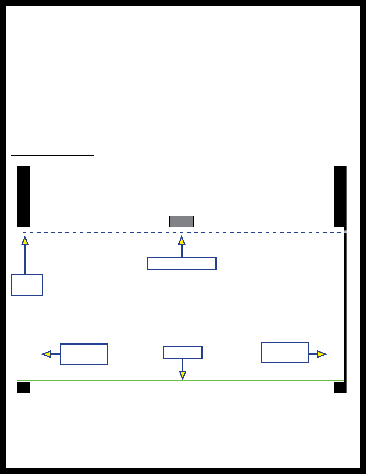
Note: This manual will refer to the “drive side” and “idler side” throughout for various instructions. The
“drive side” is the right hand side of the awning when facing the awning from the exterior of the
unit. The “idler side” is the left hand side of the awning when facing the awning from the exterior of
the unit.

Rev: 08.17.21 Page 3 CCD-0004406
Prior to Installation
All screws supporting the Solera 5000 Series Awning assembly must have a backer within the structure of
the wall of the unit. Refer to the unit's manufacturer for proper location.
Resources Required
• 2 - 3 People, depending on task
• Cordless or electric drill or screw gun
• Appropriate drive bits
• Rivet gun (if needed)
• Screwdriver
• #6 x ½" hex head screws
• #10 x ¾" screws
• #12 1¼" screws
• Wire cutters/Strippers
• Non-permanent method of marking
• Silicone sealant or tape
• Silicone lubricant
Installation
Awning Rail Installation
Note: Awning rail supplied separately.
1. Position the awning rail along the line where the roof and wall meet or:
A. For pitched awnings, a minimum of 6” above doors or windows
B. For flat awnings, a minimum of 4” above doors or windows
Note: The awning rail MUST be level and parallel with the floor line of the unit (Fig. 1).
2. After determining the awning rail's proper location, mark its position with a non-permanent
method of marking.
3. Seal the back of the awning rail with silicone sealant or tape.
4. Align the awning rail on the wall and secure with #10 x 3/4” screws, using all fastener holes.
Fig. 1
Roll Tube Assembly
Floor Line
Awning
Rail
Support Arm
Assembly
Support Arm
Assembly

Rev: 08.17.21 Page 4 CCD-0004406
Awning Installation
1. On the awning rail, mark the position of the centerlines of the support arm assemblies. Make sure that
the support arm assemblies will not interfere with any lights, vents or other obstructions.
2. Using a non-permanent method of marking, mark a perpendicular line from the awning rail down to
the floor line. This is the centerline of the support arm assembly (Fig. 2).
3. Insert the drive head assembly shaft into the end cap (Fig. 3).
A. Align the holes and secure with waxed screw.
B. Repeat process for idler head assembly at opposite end of roll tube.
Fig. 3
Drive Head
Assembly Shaft
End Cap
Note: Keep the head of the wax screw 1/8" from being fully fastened to avoid compromising the structural
integrity of the wax screw.
Fig. 2
Awning Width is from Centerline to Centerline of Support Arm Assemblies
Awning
Rail
Floor Line

Rev: 08.17.21 Page 5 CCD-0004406
Fig. 4
B
A
4. Use a screwdriver to spread open either end of the awning rail channel (Fig. 4A).
5. To protect the fabric from damage during installation, file any sharp edges or burrs from the awning
rail channel (Fig. 4B).
6. Use silicone lubricant and spray the inside of the awning rail channel (Fig. 4B).
Fig. 5 Fig. 6
Possible
Fastener
Locations
Fig. 7
7. Remove the tape from the fabric. Unroll a small portion of fabric
Note: The next steps will require three people: One to feed the polycord into the awning rail channel; two
to walk the support arm assemblies along the awning rail while the fabric slides into position.
8. Slide the polycord into the awning rail channel and walk the support arm assemblies and fabric down
the awning rail channel until the support arm assemblies are in line with the centerline marks.
9. Lift the support arm assembly up against the bottom of the awning rail and attach it to the side of the
unit with two #14 x 1 1/4" screws at the top (Fig. 5) and one screw at the bottom (Fig. 6).
Note: Make sure the awning assembly is square on the unit prior to mounting the bottom screw.
Note: Best practice for setting the awning height is to push the top of the support arm assemblies up to
be flush with the bottom of the awning rail. The awning height can be adjusted lower if desired,
but make sure that the distance from the awning rail to the top of the support arm assemblies is
consistent at both ends of the awning.
Note: Four rivets with 3/16" grip range can be used in place of the two middle and two lower screws on
laminated walls.
10. Cut the zip ties and connect the wires from the drive head assembly to a power source and run the
awning half way out.
A. Remove the wire cover to expose the fastening points.
B. Install the remaining two (2) #14 x 1 1/4” screws at any of the three locations shown (Fig. 7) in the
center of the support arm.
11. Repeat this process for the opposite side of the awning assembly.

Rev: 08.17.21 Page 6 CCD-0004406
Awning Wiring
The Solera 5000 Series Awning motors come stock with an internal 6A auto reset breaker. If this breaker
trips, it will take approximately 30 seconds to reset. Lippert recommends the awning be wired into a 15A
circuit breaker. All wire shall be 14 AWG or higher as necessary to provide 11.5V minimum at all times to the
Lippert supplied power cable connection.
1. Pull the wires from the unit through the support arm assembly. These wires may be located at the
bottom or the top of the support arm assembly.
2. Connect wiring from the unit to the switch and the awning drive head per the wiring diagram (Fig. 9).
Note: Check the switch. If the awning is running in reverse of what the switch indicates, reverse the wires.
Note: To prevent pinching of the wires, make sure all wires are routed on the outside of the pin that
secures the pitch arm to the mount arm (Fig. 10).
Securing the Fabric
1. Extend and retract the awning several times to make sure the fabric is square on the roll tube.
2. Secure the fabric in the awning rail no more than 1” inside the edge of the fabric on both ends using
a #6 x ½” hex head screw. Install the screw down through the awning rail into the fabric and the
polycord (Fig. 8).
Fig. 8
Awning Rail
1"
Fabric Stitching
#6 Hex Screw

Rev: 08.17.21 Page 7 CCD-0004406
Wiring Diagram
*Wire colors may vary depending on what switch is used.
Wire colors shown reference using a Lippert Rocker Switch.
Fig. 9
15A Circuit Breaker
per RVIA Code
(OEM Supplied)
Red
Black
Manual
Rocker
Switch
Blue
Red
Awning Motor
Battery,
Power Source
or Converter
White
Fig. 10
Ground
Power
2
3
1 4
5
6
Wires Routed
Outside Pin
End View of Wiring
Harness
Red *Jumper wire
1 to 6
Black *Jumper wire
4 to 3
White 2
Blue 5
*Jumper wires are internal
+

Rev: 08.17.21 Page 8 CCD-0004406
Installation with LED — Options
LED Light Rail Installation
Note: Solera 5000 Series Awning must be installed prior to LED Light Rail installation.
1. Seal the back of the LED light rail with silicone sealant or tape.
2. Mount the LED light rail (Fig. 11B) directly below the awning rail (Fig. 11A) and secure to the side of the
unit.
3. Remove the wire covers in the drive side mount arm.
4. Route the light wire over the top of the upper brackets on the mount arm and run the light wire down
through the support arm assembly in the same manner as the motor wire (Fig. 11C).
5. Cut the power and ground wires to the desired length and connect to the unit wiring.
A. Make sure to connect the red wire on the light side to the power wire on the unit.
B. Connect the black wire from the light side to the ground wire from the unit side.
Note: The LED light rail must be wired through a 3 amp maximum fused circuit.
LED Light Strip
Note: Awning MUST be extended to access the polycord on the awning fabric and to run the LED power
wire down the drive mount arm.
1. Starting on the drive side of the awning, slide the LED light strip (non-wired end) (Fig. 12A) onto the
polycord of the awning fabric (Fig. 12B), located close to the awning rail (Fig. 12C) down the width of
the awning fabric to the end, towards the idler side.
A
B
C
Fig. 11
A
C
B
Fig. 12
2. Flip the LED light strip drive side (wired end) up to see the back side of the light strip.
3. Install a #10 - 16 x 3/8” pan head screw (Fig. 13) into the black plastic track of the LED light strip. Make
sure to install the screw at a slight angle in between the LED light strip and the polycord in the awning
fabric, to prevent the LED light strip from sliding off the awning fabric polycord.

Rev: 08.17.21 Page 9 CCD-0004406
Note: Make sure the screw does not completely go through the polycord and into the awning fabric. Make
sure that the LED light strip is hanging straight, parallel to the ground.
Fig. 13
Fig. 15
B
A
Fig. 14
4. Depending on top wire or bottom wire installation, remove the wire covers in the drive side mount arm.
5. If bottom installation, take the LED light strip power wire (Fig. 14A) from the light track and run it down
the drive arm.
Make sure to run the wires over the center pin of the drive mount arm. If top installation, run the wires
through the top hole in the drive side mount arm (Fig. 14B) inside the unit wall and down to the switch.
Seal Wall Penetrations
1. Seal all fastener locations and wire penetrations with silicone sealant to protect against water intrusion
(Fig. 15).
2. Reinstall all wire covers onto the support arm assemblies.

The contents of this manual are proprietary and copyright protected by Lippert Components, Inc. (LCI).
LCI prohibits the copying or dissemination of portions of this manual unless prior written consent from an
authorized LCI representative has been provided. Any unauthorized use shall void any applicable warranty.
The information contained in this manual is subject to change without notice and at the sole discretion of LCI.
Revised editions are available for free download from lippert.com.
Please recycle all obsolete materials.
For all concerns or questions, please contact
Lippert Components, Inc.
Other manuals for Solera 5000 Series
4
Table of contents
Other Lippert Accessories manuals

Lippert
Lippert Solera 5000 Series User manual

Lippert
Lippert Solera Classic Awning Installation instructions

Lippert
Lippert SureShade Power Bimini Instruction Manual

Lippert
Lippert Solera 5000 Series Installation instructions

Lippert
Lippert Solera Power Installation instructions

Lippert
Lippert Solera Classic User manual

Lippert
Lippert Solera Slider User manual

Lippert
Lippert Solera Classic Awning Use and care manual

Lippert
Lippert Solera Power User manual

Lippert
Lippert 2021130655 Installation instructions