Paingone Easy User manual

Transcutaneous Electrical
Nerve Stimulator
Simple, effective pain relief
Thank you for choosing Paingone Easy. Please read this user manual carefully before use.
Model: KTR-230
Distributor
Medi-Direct International Ltd.
Unit 24, Wilford Industrial & Business Park
Ruddington Lane, Nottingham, NG11 7EP, UK
*For the temporary relief of pain as part of current
medication programme.

1 2
Paingone Easy - Quick Start Guide
“OFF/-”button
“ON/+”button
Electrode pad
Control unit
CONTRAINDICATIONS
1. Pregnant women, people with abnormally sensitive
skin, heart disease, abnormal blood pressure,
malignant tumor, serious cerebrovascular disease,
acute disease or those currently under doctor’s
treatment, should consult a doctor before using this
stimulator.
2. Do not use this stimulator on children or people with
no ability to express their own consciousness.
3. Do not use this stimulator near the heart, on the
head, mouth cavity, genitals or diseased skin
4. Patients with an implanted electronic device (for
example a cardiac pacemaker) should not use
electrical stimulation unless specialist medical
authorisation has first been obtained.
Thank you for choosing PainGone Easy. This simple
device can help you to manage your pain to maintain
a more active lifestyle. This guide will tell you how to
get started and how to get the most out of your
device.
What is Paingone Easy?
Paingone Easy is a Transcutaneous Electrical Nerve
Stimulation Device (TENS). It is applied to your skin and
emits controlled electrical pulses. Because it has no
wires or complicated settings Paingone Easy is quick
and convenient to use when you need it.
Intended Use
Paingone Easy is intended for the temporary relief
of pain
Device Overview
Before using the device for the first time
Insert the battery.
On the reverse of the device
is the battery cover. Slide this down
and away from the device.

43
Insert 1x CR2032 battery, so that the “+” symbol is
visible and facing toward you. Replace the battery
cover.
Note: 2x batteries are included with the device.
One is provided as a spare.
Attach an electrode pad to the control unit, using the
press studs.
Mode 1 – Soft pulse
Mode 2 – Strong pulse
Mode 3 – Combination soft and strong pulse
Switching modes will cause the intensity to reset to level 0.
You will need to increase the intensity again using the
“on/+” button.
Powering off The device will automatically cycle through a
pre-set programme of therapeutic pulses. The treatment will
last for 15 minutes. After this time the device will automatically
turn off. You can also force the device to power off by
pressing and holding the “OFF/ –” button for 3 seconds. The
device will beep and the green light will turn off.
You can begin a new therapy session by re-activating the
device with the “on/+” button. The maximum recommended
time for any therapy session is 60 min.
If it is not attached to the skin the device will always
automatically turn off after 1 minute, to conserve battery life.
After using the device, replace the protective film onto the
electrode pad. Store the device in a dry, ventilated place.
Replacing the electrode pads
Each electrode pad can be used approximately 80 times
(based on 2 uses per day, with 15 minutes application time).
When an electrode pad has lost its stickiness entirely it should
be replaced with a brand new pad.
ONLY USE OFFICIAL PAINGONE EASY ELECTRODE PADS WITH
THIS DEVICE. Please do not try to attach any other electrode
pad to this product.
ONLY USE ONE PAIR OF PADS PER USER OF THE DEVICE.
To purchase replacement electrode pads contact Tower
Health Ltd. Tel: 0800 953 1666
E-mail: [email protected]
Replacing the battery
One CR2032 battery provides approximately 8 hours use.
Once the battery charge is exhausted, replace with a new,
fully charged battery.
Further notes on usage
If Paingone Easy is not in contact with the skin, it will not emit
an electrical pulse. The treatment intensity will not be
adjustable if the electrode has poor contact with your skin.
Cleaning and maintenance
Keep the surface of electrode pads clean. Avoid dust, oily
matter and viscous matter. These can cause the adhesiveness
of the electrode pads to decline.
Remove the protective film from the electrode pad.
The device is now ready to use.
How to use Paingone Easy
Apply the electrode pad to the desired area of the
body. Ensure that the pad is firmly pressed against the
skin. A poor connection will affect performance of the
device.
Press and hold the “ON/+” button briefly to activate
the device. The device will beep and a green light will
show. Now, press the “on/+” button repeatedly to
increase the intensity to a level you find comfortable. If
the intensity is too strong, press the “OFF/ -” button to
reduce the strength of the pulses.
The device will beep with each step up or down in
intensity. There are 12 steps of intensity in total.
Changing Modes
While the device is in use, you can switch between 3
different treatment modes. To do this hold down the
“on/+” button.

65
The electrode pads can be washed to restore adhesiveness.
Remove the pad from the device before washing. Allow to dry
thoroughly before re-attaching to the control unit.
The control unit does not require maintenance or calibration. Do
not attempt to open the control unit for any reason. If a fault is
suspected, contact the point of purchase.
Please remove the batteries if the stimulator is not to be used for a
long time.
Storage
1) Please keep the stimulator out of reach of children
2) Do not store the device in places where it will be exposed to
direct sunlight, high temperature or moisture.
3) Please store the device in a dry and ventilated space
2. Product disposal
In order to avoid environmental pollution, please dispose this
Device according to local environmental requirements. Do not
discard in your standard waste disposal.
Troubleshooting
There is no
output (electrical
pulses) or the
output feels low
The battery is
running low or
running out
The electrode
pad is damaged
or dirty, has no
stickiness or is
making poor
contact with the
skin
Skin is too oily
The device is
damaged
Replace the
battery
Replace with a
new electrode
pad
Wipe skin with a
wet towel or
alcohol Allow to
dry fully before
using the device
Contact the point
of purchase
The device does
not power up
correctly
The battery is
installed
incorrectly
The battery is
running low or
running out
The button is
damaged
Use CR2032
button batteries.
Please install the
battery properly
with the “+” pole
facing upwards
and the “-” pole
facing
downwards
Replace the
battery
Contact the point
of purchase
The device does
not emit any
"beep" sound
The speaker is
damaged
Contact the point
of purchase
The buttons are
not functioning
correctly
The battery is
running low or
running out
The button is
damaged
Replace the
battery
Contact the point
of purchase
Problem Analysis of cause Recommended
Solution
The skin is
strongly
irritated/shows
signs of redness
The treatment has
been applied too
long
The intensity is set
too high
The electrode
pad is not making
good contact
with the skin
There may be an
allergic reaction
to the electrode
pad
The electrode
pad is dirty
Limit treatments to
15 minutes
Decrease the
intensity to a more
comfortable level
Press the
electrode pad
firmly against the
skin to improve
contact
Cease use of the
device
Clean the
electrode pad

8
7
3. Technical parameters and specification
3.1 Product specification
Product Name
Model
Power supply
Safety category
Product service life
Product dimensions
Storage time
software version
Transcutaneous Electrical Nerve Stimulator
KTR-230
d.c.3V 30mA(CR2032)
BF type
≥ 3 years
Φ51×13.5 (mm)
≤6 months
KTR- 230-119A-V1.0
3.2 Environmental conditions
Normal working condition
Storage condition
Transportation condition
Temperature
+5℃-+40℃
-25℃-+70℃
-10℃-40℃
Humidity
15%-93%RH
0-93%RH
15%-93%RH
Barometric pressure
700hPa-1060hPa
700hPa-1060hPa
700hPa-1060hPa
3.3 Electrical performance
Pulse frequency
Pulse width
Direct current component
Peak pulse voltage
Electric quantity of single pulse when
the output amplitude is maximum
Maximum output energy of single pulse
The effective value of maximum output
amplitude
The peak value of output voltage when
conducting open loop measurement
The effect of output end open circuit
and short circuit
Adjustment of output amplitude
Rated load impedance
Timing time of therapy stimulator
1Hz—120Hz
20μs~400μs
0V
<60V
﹥7μC
≤300mJ
≤25V(50mA)
≤500V
Can endure the effect of output end
open circuit and short circuit and the
performance should not be weaken.
Continuous and uniform, minimum
output should be no bigger than 2% of
maximum output.
500Ω with a permissible deviation
of ±10%
15 minutes with a permissible
deviation of ±10%
The average working time with
no malfunction
Product software version No.
≥1000 hours
KTR-230-119A- V1.0
4. Safety precautions
■ The purpose of the warning signs and symbols in this user
manual is to make sure that the user can use this product
safely and correctly, and thus prevent damage to the user
or other people.
■ Warning signs, symbols and their meanings are as follows:
Warning signs Meaning
Indicate when wrongly used, it may cause personal
casualty or serious injury.
Indicate when wrongly used, there is a possibility of
personal casualty or serious injury.
Indicate when wrongly used, there is a possibility of
personal injury or things get damaged.
Danger
Warning
Warning
Attention
Danger
Never use this stimulator along with other medical electronic
stimulators, such as cardiac pacemaker, artificial heart-lung which
are used to maintain life, and electrocardiograph. Otherwise it may
cause danger.
If the user is using high frequency surgical equipment and this
therapy stimulator at the same time, then there might be burn in
the place where the electrode slice is pasted to or damage to the
stimulator; If this stimulator is used in the vicinity (1m) of short
wave or microwave therapy stimulator, then the output of this
stimulator might not be stable.
1. Do not use this stimulator in places where there are high heat,
inflammables and electromagnetic radiation.
2. Do not use this stimulator while bathing or sleeping.
3. Do not modify the stimulator, or else electric shock might occur.
4. Do not inhale or swallow small parts, which might lead to
life-threatening condition.
5. Do not conduct servicing or maintenance while the device is in
use.
6. Do not apply the electrodes near the thorax, which may increase

10
9
Is the battery low
power or drained?
Replace new
batteries.
Contraindications
Attention
1.Do not move the stimulator while using, or when the user wishes
to
change treated area, first be sure to turn off the stimulator then use
it, or it might cause strong stimulation.
2. If the user doesn’t feel well due to stimulator anomaly, please
stop using at once and consult a doctor.
3. If the stimulator is not to be used in a long time, please take out
the battery to avoid leakage which may damage the stimulator.
4. Do not use this stimulator under circumstances that are beyond
the range of application.
5. Do not use or contact with the product for a long time.
Do not arbitrarily disassemble, repair and reform this stimulator,
otherwise it might cause malfunction or electric shock accidents.
the risk of cardiac fibrillation.
7. Stimulation should not be applied across or through the head,
directly on the eyes, covering the mouth, on the front of the neck,
(especially the carotid sinus), on private parts, parts with skin
disease, or from electrodes placed on the chest and the upper
back or crossing over the heart.
1. Pregnant women, people with abnormally sensitive skin, heart
disease, abnormal blood pressure, malignant tumor, serious
cerebrovascular disease, acute disease or currently under doctor’s
treatment, should consult a doctor before use this stimulator.
2. Do not use this stimulator on children or people with no ability to
express their own consciousness.
3. Do not use this stimulator near the heart, on the head, mouth
cavity, private parts, parts with skin disease and so on.
4. Patient with an implanted electronic device (for example a
cardiac pacemaker) should not be subjected to stimulation unless
specialist medical opinion has first been obtained.
5. EMC statement
6. Symbols
①Models KTR-230 need special precautions regarding
EMC and need to be installed and put into service according
to the EMC information provided in the accompanying
document;
②Portable and mobile RF communications equipment can
affect models KTR-230.
Warning:
1) The use of accessories, transducers and cables other
than those specified with the exception of transducers and
cables sold by the manufacturer of the models KTR-230 as
replacement parts for internal components, may result in
increased emissions or decreased immunity of the models
KTR-230.
2) Models KTR-230 should not be used adjacent to or
stacked with other equipment Guidance and Manufacturer’s
declaration can be seen in the attachment.
Graphic symbol Meaning
Product batch number symbol
Product serial number symbol

12
11
Guidance and manufacturer’s declaration – electromagnetic emissions
The models KTR-230 are intended for use in the electromagnetic
environment specified below. The customer or the user of the models
KTR-230 should assure that it is used in such an environment.
Emissions Compliance Electromagnetic environment-- guidance
7. Attachment
Manufacturer
Date of manufacture
Authorised representative in the European community
Caution
Danger warning
BF type applied part
Indoor use only
EC REP
Prohibition (things that are not allowed to do)
Constraint (things that shoule be obeyed)
Avoid sunlight
Low-frequency electromagnetic radiation
Keep dry
IP22
CE symbol and Notified body code
“WEEE (Waste Electrical and Electronic Equipment)”.
The waste products should be handled legally.
Product package should be recycled.
Dustproof waterproof level. It can prevent solid object
larger than 12mm from intruding, and when tilt for 15
degrees, it can still prevent waterfrom intruding, so no
harmful effect will be created.
CAUTION, Avoid injury. Read and understand owner’s
manual before operating this product.
0123
The models KTR-230 use RF energy only
for its internal function.
Therefore, its RF emissions are very low
and are not likely to cause any interference
in nearby electronic equipment.
The models KTR-230 are suitable for
use in all establishments, including
domestic establishments and those
directly connected to the public low-
voltage power supply network that supplies
buildings used for domestic purposes.
RF emissions
CISPR 11 Group 1
RF emissions
CISPR 11 Class B
Harmonic
emissions
IEC 61000-3-2
Voltage
fluctuations
/flicker
emissions
IEC 61000-3-3
Not applicable
Not applicable
Guidance and manufacturer’s declaration – electromagnetic immunity
The models KTR-230 are intended for use in the electromagnetic
environment specified below. The customer or the user of the models
KTR-230 should assure that it is used in such an environment.ment.
Immunity
test
IEC 60601
test level
Compliance
level
Electromagnetic environment
--guidance
Electrostatic
discharge
(ESD)
IEC
61000-4-2
Electrical fast
transient/
burst IEC
61000-4-4
Surge
IEC
61000-4-5
±1 kV line
to line
±2 kV line
to earth
Not
applicable
Mains power quality should be
that of a typical commercial or
hospital environment.
±2kV for
power supply
lines ±1 kV
for Input/
output lines
Not
applicable
±8 kV contact
±2 kV, ±4 kV,
±8 kV, ±15 kV
air
±8 kV contact
±2 kV, ±4 kV,
±8 kV, ±15 kV
air
Floors should be wood,
concrete or ceramic tile. If
floors are covered with
synthetic material, the relative
humidity should be at least 30%.
Mains power quality should be
that of a typical commercial
or hospital environment.

14
13
Guidance and manufacturer’s declaration – electromagnetic immunity
The models KTR-230 are intended for use in the electromagnetic
environment specified below. The customer or the user of the models
KTR-230 should assure that it is used in such an environment.
Immunity
test
IEC 60601
test level
Compliance
level
Electromagnetic
environment – guidance
Voltage
dips, short
interruptions
and voltage
variations
on power
supply
input lines
IEC
61000-4-11
Power
frequency
(50/60 Hz)
magnetic
field
IEC
61000-4-8
30 A/m30 A/m
<5 % UT
(>95% dip
in UT.)
for 0.5 cycle
40 % UT
(60% dip
in UT) for 5
cycles 70% UT
(30% dip in UT)
for 25 cycles
<5% UT
(>95 % dip in
UT) for 5 sec
Mains power quality
should be that of a typical
commercial or hospital
environment. If the user of
the models KTR-230
requires continued
operation during power
mains interruptions, it is
recommended that the
models KTR-230 be
powered from an
uninterruptible power
supply or a battery.
Power frequency magnetic
fields should be at levels
characteristic of a typical
location in a typical
commercial or hospital
environment.
Not
applicable
NOTE UT is the a.c. mains voltage prior to application of the test level
Conducted
RF
IEC
61000-4-6
Radiated
RF
IEC
61000-4-3
specifications
for
ENCLOSURE
PORT
IMMUNITY
to RF
wireless
communication
equipment
(Refer to
table 9 of
IEC
60601-1-2:
2014)
3 Vrms
150 kHz to
80 MHz
6 Vrms in
ISM
bands
10 V/m
80 MHz to
2.7 GHz
385MHz-
5785MHz
Test
specifications
for
ENCLOSURE
PORT
IMMUNITY
to RF
wireless
communication
equipment
(Refer to
table 9 of
IEC
60601-1-2:
2014)
Not
applicable
Not
applicable
10 V/m
80 MHz
to 2.7 GHz
385MHz-
5785MHz
Test
Portable and mobile RF
communications equipment
should be used no closer
to any part of the models
KTR-230, including cables,
than the recommended
separation distance
calculated from the
equation applicable to
the frequency of the
transmitter.
Recommended
separation distance
d=[3,5/V1]×P1/2
d=1.2×P1/2 80 MHz
to 800 MHz
d=2.3×P1/2 800 MHz
to 2.7 GHz
where P is the maximum
output power rating of the
transmitter In watts (W)
according to the transmitter
manufacturer and d Is the
recommended separation
distance in meters (m).
Field strengths from fixed
RF transmitters, as
determined by an
electromagnetic site survey,
a should be less than the
compliance level in each
frequency range.b
Interference may occur In
the vicinity of equipment
marked with the following
symbol:

16
15
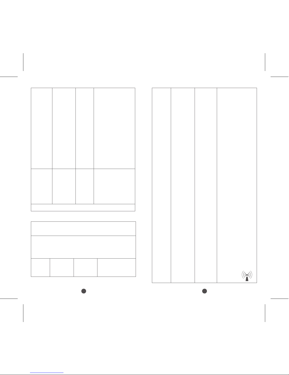
NOTE 1 At 80 MHz and 800 MHz, the higher frequency range applies.
NOTE 2 These guidelines may not apply in all situations. Electromagnetic
propagation is affected by absorption and reflection from structures,
objects and people.
a. Field strengths from fixed transmitters, such as base stations for radio
(cellular/cordless) telephones and land mobile radios, amateur radio, AM
and FM radio broadcast and TV broadcast cannot be predicted theoretically
with accuracy. To assess the electromagnetic environment due to fixed RF
transmitters, an electromagnetic site survey should be considered. If the
measured field strength in the location in which the models KTR-230 are
used exceeds the applicable RF compliance level above, the models
KTR-230 should be observed to verify normal operation. If abnormal
performance is observed, additional measures may be necessary, such
as re-orienting or relocating the models KTR-230.
b. Over the frequency range 150 kHz to 80 MHz, field strengths should be
less than 3 V/m.
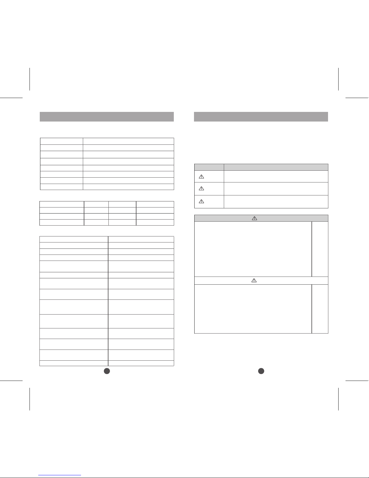
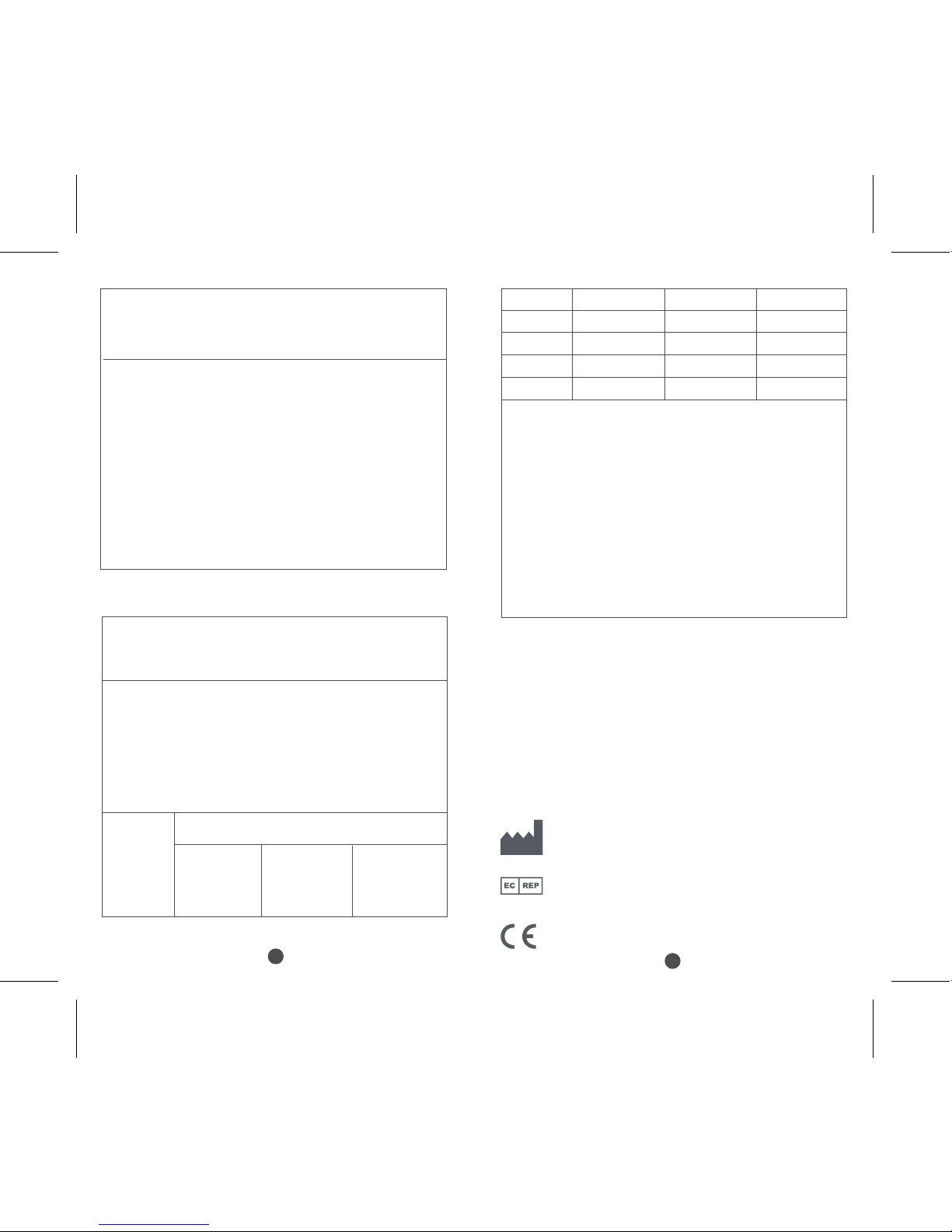
Recommended separation distances between portable
and mobile RF communications equipment and the models KTR-230
The models KTR-230 are intended for use in an electromagnetic
environment in which radiated RF disturbances are controlled. The
customer or the user of the MODEL KTR-230 can help prevent
electromagnetic interference by maintaining a minimum distance
between portable and mobile RF communications equipment
(transmitters) and the models KTR-230 as recommended below,
according to the maximum output power of the communications
equipment.
Rated
maximum
output power
of transmitter
W
Separation distance according to frequency of transmitter
m
150kHz to 80MHz
d=1.2×P1/2
80MHz to 800MHz
d=1.2×P1/2
800MHz to 2,5GHz
d=2.3×P1/2
0.01 0.12 0.12 0.23
0.1 0.38 0.38 0.73
1 1.2 1.2 2.3
10 3.8 3.8 7.3
100 12 12 23
For transmitters rated at a maximum output power
not listed above, the recommended separation
distanced in metres (m) can be estimated using the
equation applicable to the frequency of the transmitter,
where P is the maximum output power rating of the
transmitter in watts (W) according to the transmitter
manufacturer.
NOTE 1 At 80 MHz and 800 MHz, the separation
distance for the higher frequency range applies.
NOTE 2 These guidelines may not apply in all situations.
Electromagnetic propagation is affected by
absorption and reflection from structures, objects
and people.
Warranty
Please retain this warranty for reference in case after-sales repair or
maintenance is required.
The terms of the warranty are as follows:
Under normal operating conditions this product is covered by a
one-year warranty against manufacturing fault. In the unlikely
event of a manufacturing fault being encountered during this
period, the device will be repaired or replaced free of charge.
Cover is from the date of receipt.
Accidental damage or damage caused through misuse is not
covered by this warranty.
Shenzhen Kentro Medical Electronics Co.,Ltd
N0.3, Xihu industry zone, Xikeng Village, Henggang Town,
Longgang District, Shenzhen, Guangdong, China
Wellkang Ltd
Suite B, 29 Harley Street LONDON W1G 9QR, England, United
Kingdom Tel: +44 (20)30869438, 32876300 Fax: +44(20)76811874
0123
This manual suits for next models
1
Table of contents