Palas CD 2000 Type A User manual

Operating Manual
Corona-Discharge Unit
CD 2000
Type A: 2 –18 m³/h
Type B: 3 –36 m³/h
Version LNCE 6000; date 2/2008
PALAS GmbH
Partikel- und Lasermesstechnik
Greschbachstrasse 3b
76229 Karlsruhe

OPERATING MANUAL CD 2000
Palas®GmbH, Karlsruhe, Version V002022014
2
Content
Important Notes for Operation of Corona Discharge Unit CD 2000! ........................................ 3
1. Check of delivery .................................................................................................................... 4
1.1 Checking of accessory equipment supplies...................................................................... 4
2. Safety conditions / Intended use ........................................................................................... 5
2.1 General safety conditions ................................................................................................. 5
2.2 Intended use ..................................................................................................................... 5
2.3 Responsibility of the operator .......................................................................................... 5
3. Short Operating Instructions.................................................................................................. 6
3.1 Connections ...................................................................................................................... 6
3.2 Switching-on Procedure.................................................................................................... 6
3.3 Switching-off Procedure ................................................................................................... 6
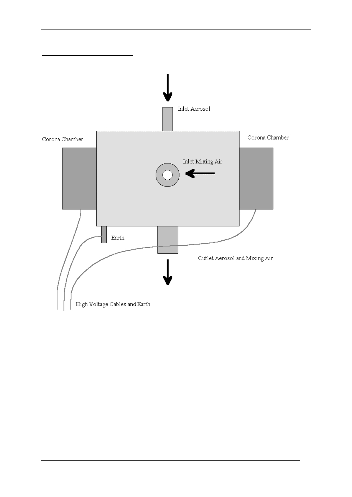
4. Function Principle ............................................................................................................... 7
5. Electrical Adjustment of Corona Ionization Chambers.......................................................... 8
5.1 Principle: ........................................................................................................................... 8
5.2 Procedure:......................................................................................................................... 8
5.3 Adjusting the external potentiometers with scale:.......................................................... 8
6. Malfunctions ........................................................................................................................ 10
6.1 FAQs ................................................................................................................................ 10
6.2 General............................................................................................................................ 10
7. Maintenance ........................................................................................................................ 11
8. Technical Data for Standard Equipment.............................................................................. 12
8.1 Electrical data.................................................................................................................. 12
8.2 Mechanical data (standard values)................................................................................. 12
9. Spare parts list / accessories list .......................................................................................... 13
9.1 The following replacement parts are available: ............................................................. 13
10. Transport, packaging and storage...................................................................................... 14
10.1 Packaging: ..................................................................................................................... 14
10.2 Storage: ......................................................................................................................... 14
10.3 Transport: ..................................................................................................................... 14
11. Disposal of the Discharge Unit CD 2000 ............................................................................ 15
12. Feedback form.................................................................................................................... 16

OPERATING MANUAL CD 2000
Palas®GmbH, Karlsruhe, Version V002022014
3
Important Notes for Operation of Corona Discharge Unit CD 2000!
Start operation of Corona-Discharge Unit only after thoroughly study of operating manual.
The manufacturer is not liable for damages caused by improper operating, false starting of
the unit, misuse or cleaning.
Please take note of the following points:
- The standard equipment may only be operated in dry rooms under atmospheric
environmental pressure and at room temperature. The manufacturer will not be liable
with regard to the operating guarantee, if operating takes place under different
environmental conditions, such as, corrosive or explosive environment, electric or
electromagnetic fields, operating within areas of ionizing radiation, within areas
conductive to shock or vibration.
- Besides discharging also electric sparks are possible in the discharge chambers. Thus only
gas that is definitely not flammable may be used as mixing air and aerosols.
- If any damage at cables, plugs or other parts of the discharge unit is visible do not
operate the discharge unit. In order to eliminate the defect please contact the
manufacturer.
- The grounding cable of corona-discharge must be connected.
- Use only original spare parts!
- While operation, the corona-discharge-chambers produce ozone. The mixed aerosol
should not contaminate the air in the place where people are working.
Attention: Aerosols might be dangerous to your health. That’s why they ought not to be
inhaled. It might also be necessary to wear protective clothes. Please pay attention to the
correspondent standards and safety rules.
Explanation of warning signs:
This sign is placed near parts where dangerous high voltage is present.

OPERATING MANUAL CD 2000
Palas®GmbH, Karlsruhe, Version V002022014
4
1. Check of delivery
1.1 Checking of accessory equipment supplies
Please check immediately after unpacking the instrument if it shows any damages due to
the transport.
If the instrument is damaged, you may not set it to work. Damages may lead to unsafe
operation because of the high voltage in the instrument.
Please check if the supplied accessory equipment of the CD 2000 is complete.
The following parts are attached to the system:
1 power cord
1 operating manual
1 electrotronical control unit
1 Discharge unit with a cable with three connectors:
Negative Ion
Positiv Ion
Grounding

OPERATING MANUAL CD 2000
Palas®GmbH, Karlsruhe, Version V002022014
5
2. Safety conditions / Intended use
2.1 General safety conditions
For safety reasons, under no circumstances may the machine be commissioned if there
is visible damage. In this event, please contact Palas® (Tel.: 0721/96 213-0).
The discharge system CD 2000 has been permanently adjusted by the manufacturer to
the mains voltage requested in the order. Please verify, if the mains voltage indicated on
the type label corresponds to the mains voltage at the respective place of instalment.
Attention: The manufacturer is not reliable for any damages caused by another voltage
supply as stated on the instrument
Only use original spare parts! Please contact the manufacturer whenever necessary.
2.2 Intended use
The discharge system CD 2000 was designed to create a soot similar to diesel soot by
graphite electrodes and to disperse this soot into air/ gas stream.
The manufacturer is not responsible for any damage, which arise due to incorrect
operation, cleaning, error in operation or the measurement of aerosols which gas
conditions or compound the instrument is not specified for.
The machine may only be operated in dry rooms, under atmospheric ambient pressure
and at room temperature.
Operating under other ambient conditions such as in corrosive or explosive
environments, in strong electric or electromagnetic fields, in areas with ionising
radiation as well as in areas subject to impact and vibration is not covered by any
functional guarantee by the manufacturer
2.3 Responsibility of the operator
The device was designed and built in consideration of the standards to be adhered to. It
therefore represents state-of-the-art technology and allows a high degree of safety in
operation.
Please only operate the dust disperser of the discharge system CD 2000 after reading
carefully the manual.
Trained personal
Be sure that the machine cannot be used by unauthorized personnel.
Caution: Depending on the type, aerosols can pose a health hazard. They should
therefore not be inhaled. When working with or when around hazardous materials, care
must also be taken to wear appropriate protective clothing (respirator mask). Please
follow all applicable guidelines and accident prevention regulations.

OPERATING MANUAL CD 2000
Palas®GmbH, Karlsruhe, Version V002022014
6
3. Short Operating Instructions
3.1 Connections
Connect mixing air, aerosol inlet and outlet to the discharge chamber
Connect grounding cable of HV-power supply to discharge chamber
Connect high-tension lead to positive/negative outlet of power supply.
Pay attention to polarity!!
Connect power cord to HV-power supply
3.2 Switching-on Procedure
FIRST Deliver mixing air. Adjust volume flow. On this occasion consider the
allowable volume flow range. The mixing air flow must always be bigger
than the aerosol flow at the aerosol inlet.
THEN Switch on the discharge unit.
AT LAST Deliver aerosol.
Thus it is assured that aerosols do not enter the discharge chamber.
3.3 Switching-off Procedure
Follow the switching on procedure in reverse order:
Aerosol off, discharge off, mixing air off.

OPERATING MANUAL CD 2000
Palas®GmbH, Karlsruhe, Version V002022014
7
4. Function Principle
The dust or liquid aerosol is supplied to the inlet . The particles in these aerosols carry some
charge and they have to be discharged.
The clean pressurized air is delivered into the mixing air inlet. Mixing air flow is lead through
two ionization chambers which are driven by positive/negative high tension. In these
chambers the air is enriched with ions by the corona discharge.
The aerosol air flow and the mixing air flow enriched with ions will then be mixed in the
mixing chamber just before the outlet. By means of ions in the mixing air, the charge of the
particles in the aerosol is neutralized. This takes a certain time which means that the
complete discharge procedure takes place mainly in the volume after the outlet of the
discharge unit. (For example in the following tubes or in the upper part of a filter holder). An
estimate for the needed time for the discharge process is around 0,5 seconds. Good
discharge was found in applications assuring a time longer than 0,2 seconds.

OPERATING MANUAL CD 2000
Palas®GmbH, Karlsruhe, Version V002022014
8
5. Electrical Adjustment of Corona Ionization Chambers
In order to assure a correct function of the discharge unit, it is important that the electrical
working point is adjusted in the right way.
5.1 Principle:
The current from the negative and positive high-voltage supplies is set to a value so
high that it is completely carried by the corona-discharge. No, or only a few sparks
are allowed. This current is set by adjusting the current limiting circuit of the high voltage
supplies to the chosen value of maximum current.
The voltage limit is set a little higher than necessary for the maximum current. Due
to this, the current will always keep its value, even if conditions such as temperature or
state of electrodes are changing.
5.2 Procedure:
Positive and negative high-voltage supply and discharge unit are independent of
each other and can be separately adjusted.
1) Start operating the discharge unit but without aerosol supply. (See First Set-up)
Recommendation: Mixing air volume flow should be set to 5 m3/h (4 to 10 m3/h is
useable).
Connect digital voltmeter to the monitor-output on the back side of the high-
voltage supply unit:
as first to the monitor output for Imon of the positive high voltage part; after this
part is set, then connect the voltmeters to the 'negative' part.
Setting for voltmeter is: voltage measurement 0 to 10 V.
2) The adjusting potentiometers are mounted on the front plate. They have a scale
from 0 to 999 and can be set easily and reproducible by hand.
5.3 Adjusting the external potentiometers with scale:
Relation between scales and voltage or current:
voltage (Upos/Uneg): 1000 scales correspond to 6000 V
1 scale corresponds to 6 V
current (Ipos/Ineg): 1000 scales correspond to 1000 µA
1 scale correspond 1 µA

OPERATING MANUAL CD 2000
Palas®GmbH, Karlsruhe, Version V002022014
9
For example, the standard setting for the current limiting at 20 µA (which means 0.2 V on
the monitor output) is now at 20 scales.
3) Adjustment procedure
- Regulate Adjusting potentiometer for voltage down entirely
- turn current adjusting potentiometer to a high value (200 scales)
- now increase the output voltage by turning the potentimeter for Upos upwards and look
for the monitoring value for the current on the digital voltmeter.
For standard setting: As soon as the monitoring value reaches 0.2V (corresponds to 20µA),
increase the scales of the Upos-potentiometer by 200 scales.
Then turn down the Ipos-potentiometer to 20 scales.
Now the setting for the positive high voltage is adjusted. The digital voltmeter should show
now around 0.2V as monitoring value.
When measuring the monitoring value for Umon, the voltage seen there is lower than
adjusted with the Upos-potentiometer because the HV-supply now works with current-
limiting and therefore decreases the output voltage.
The negative output is adjusted in the same way as the positive output:
- preset potentiometers for Uneg and Ineg
- connect voltmeter
- increase Uneg and look for Ineg: increase Uneg by 250 scales when reaching the 0.2V on
voltmeter
- set potentiometer for Ineg to 20 scales.
Caution! In order to keep the values given by the EMC-directive, the current should be so
low that no sparking takes place. This will be correct as long as the current is kept
at 20 A or less.

OPERATING MANUAL CD 2000
Palas®GmbH, Karlsruhe, Version V002022014
10
6. Malfunctions
If the discharging of the particle is not sufficient then please check if the electrical control
unit has electrical power.
If other malfunctions may arise, please contact manufacturer.
Palas GmbH
Greschbachstr. 3b
76229 Karlsruhe, Germany
Telephone: +49 (0)721/96 21 30
E-mail: support@palas.de
(please indicate the serial number of the instrument within the email)
A device that obviously does not function perfectly may not be operated further!
6.1 FAQs
Table with known questions:
(Questions are currently being collected and will be listed in the next revision of this
document)
6.2 General
No components may be serviced or replaced in the discharge system CD 2000 without
instruction from a Palas® employee. In the event of infringement, the customer loses their
warranty claims; in addition Palas® is not liable for the damage arising.
In case of problems with the discharge system CD 2000 please contact Palas® GmbH (Tel.:
0721/96 213-0).

OPERATING MANUAL CD 2000
Palas®GmbH, Karlsruhe, Version V002022014
11
7. Maintenance
During the application of the discharge unit always make sure that mixing air flow will be
supplied first then the aerosol flow.
When switching off remove aerosol flow first then mixing air flow. Otherwise the ionization
chambers can become contaminated. A high mixing air flow (depending on version, max. 18
or 36 m3/h) can clean these chambers .
Dismantling can only be effected by the manufacturer as an exact adjustment of the
components is essential when reassembling it.
The function of the unit can be controlled by measuring the corona current at IMon while
operating. Using the standard settings, there should be shown approx. 0.2 V, which
corresponds to approx. 20 µA.

OPERATING MANUAL CD 2000
Palas®GmbH, Karlsruhe, Version V002022014
12
8. Technical Data for Standard Equipment
8.1 Electrical data
mains supply voltage 100 to 250 V AC / 47 to 63 Hz
consumed power 50 W
mains fuse M 2A / 250 V
high-voltage supplies
Positive and negative high voltage is provided by two independent power supplies.
voltage (max.)
current (max.)
positive
6000 V
1000 µA
negative
6000 V
1000 µA
Monitoring of high voltage
voltage (blue socket): 0 - 6000 V = 0 - 10 V
current (red socket): 0 - 1000 µA = 0 - 10 V
8.2 Mechanical data (standard values)
There are two versions of the mechanical part of the CD-2000 with different mixing air
flows:
type A is for air flows from 2 to 18 m³/h
type B is for air flows from 3 to 36 m³/h
inlet:
aerosol:
volume flow:
0 - 4 m³/h
connection:
da = 8 mm; di = 6 mm
mixing air:
cleaned, dry pressurized
air
type A, 'small'
type B, 'big'
volume flow:
2 - 18 m³/h
3 - 36 m³/h
hose coupling for hose:
i 6 mm
a 8 mm
i 13 mm
outlet:
aerosol and charged mixing air
connection:
da = 16 mm
di = 12 mm

OPERATING MANUAL CD 2000
Palas®GmbH, Karlsruhe, Version V002022014
13
9. Spare parts list / accessories list
9.1 The following replacement parts are available:
Aerosol inlet tube for CD 2000

OPERATING MANUAL CD 2000
Palas®GmbH, Karlsruhe, Version V002022014
14
10. Transport, packaging and storage
10.1 Packaging:
Please keep the original packaging, so that if it should become necessary (for service or
maintenance) you can use this packaging to send the unit back to Palas®.
10.2 Storage:
If the unit will not be used for a longer period, the instrument should be cleaned. Then the
unit should be stored in a dry location.
10.3 Transport:
When transporting by hand take care about the weight. Please see also technical parameter.
For all other types of transport (such as shipping), the unit must first cleaned and the
instrument should be packed safty for transportation. Please use the original transport
packaging.

OPERATING MANUAL CD 2000
Palas®GmbH, Karlsruhe, Version V002022014
15
11. Disposal of the Discharge Unit CD 2000
Once the discharge system CD 2000 has reached the end of its lifetime, please contact
Palas® (0721-96213-0) for proper disposal.

OPERATING MANUAL CD 2000
Palas®GmbH, Karlsruhe, Version V002022014
16
12. Feedback form
In order to continuously improve our Instruction Manual, we request you to fill in this form
and to send it back to us. Many thanks for your feedback!
How to contact us:
Address: Greschbachstraße 3 b, 76229 Karlsruhe, Germany
This evaluation concerns (Instruction Manual, version): CD 2000, V002022014
Please give us your contact details:
Company: ________________________________________________________________
Name: ___________________________________________________________________
Address:__________________________________________________________________
Telephone number or e-mail: _________________________________________________
Were the instructions clearly formulated and easy to understand?
yes no
If no, please give details here: ________________________________________________
_________________________________________________________________________
Was information missing for you?
yes no
If yes, please give details here: ________________________________________________
_______________________________
Were you satisfied with the structure of the Instruction Manual? Did you quickly find the
information you were looking for?
yes no
If no, please give details here: ________________________________________________
_________________________________________________________________________
Were you satisfied with the telephone service in the event of technical problems?
yes no
If no, please give details here: ________________________________________________
_________________________________________________________________________
Here you can tell us what else seems important and helpful for you:
_________________________________________________________________________
_________________________________________________________________________
This manual suits for next models
1
Table of contents