manuals.online logo
Brands
  1. Home
  2. •
  3. Brands
  4. •
  5. PalatiumCare
  6. •
  7. Keypad
  8. •
  9. PalatiumCare PalCare PAL-106050 User manual

PalatiumCare PalCare PAL-106050 User manual

1
Document # 106050 © 2019 PalatiumCare, Inc - Rev 1.3.3
All-In-One (AIO)
Keypad Installation Guide
PAL-106050 / 60 / 70
Thank you for purchasing the PalCare AIO Keypad. The AIO Keypad is a completely
integrated access control and intrusion monitoring system that can be battery powered or
externally powered. The keypad includes integrated sounders and transmitters to make
installations simpler, faster, and more reliable. The PalCare AIO Keypad is compliant with
NFPA Life Safety Code 101 and UL294.
The AIO Keypad is used to protect doorways from unauthorized entry or exit. It is typically
installed on perimeter doors of the facility and doorways between secure and unsecure zones
like a memory care wing. If the door is opened without a valid code entered into the keypad,
it will audibly sound an alarm tone and send a message to the nurse call system alerting staff.
If a staff member wants to go through the door without sending an alert, they can enter a valid
code in the keypad allowing them to pass through the doorway without an alert. This reduces
the number of nuisance alerts being sent to staff and increases safety of your residents.
The AIO Keypad also includes advanced features and configuration options to help in various
scenarios that may be encountered in your facility. These features are explained in the
keypad configuration section below.
For technical support, please contact PalCare at 888-725-2848 or [email protected]
2
Document # 106050 © 2019 PalatiumCare, Inc - Rev 1.3.3
Operating Specifications
Dimensions: 5 ½” x 4” x 1 ½”
Enclosure Color: White
Color Membrane: Grey and Blue
Weight: 14 oz.
Environment: 40°F - 120°F (Non-Condensing)
Electrical Specifications
Supply Voltage*
8 –32 VDC
Input Current Max (Dry Relay Configuration)
350 mA
Input Current Max (Wet Relay Configuration)**
2350 mA
External Sounder*
Transistor Output
100ma Max @ +/- 10% of Keypad Supply Voltage
Relay Output
Dry Form C
Contacts Rated 2 A @ 30 VDC
Door Contact Input
Dry Contact Closure Required
Request to Exit (REX) Input
Dry Contact Closure Required
Maglock Alarm Input
Dry Contact Closure Required
Maglock Stopper Input
Dry Contact Closure Required
Bond Sensor Input
Dry Contact Closure Required
* Must be UL294 rated.
** Actual current consumption is 350 mA plus the external load connected to keypad relay.
Battery Power Requirements
2x Panasonic CR123A 3V Lithium Batteries
The AIO Keypad only supports a single keypad when running on batteries. If operating the keypad
from batteries, please ensure both batteries are installed. When operating from batteries, the device
will turn off the backlighting LEDs and the relay will not activate to conserve battery power. These
features will function properly when running the keypad from an external power supply. The use of
electronic locks with the keypad is not supported on battery power. When running on battery power,
the unit enter low battery state at 2.8 volts. When the battery drops to 2.6 volts, the unit will enter
critical low battery state. Please see the troubleshooting section below for more information about low
battery states. It is recommended to run the keypad from either batteries or external power, but not
both.
Wire Requirements
Recommend cable is 18 gauge shielded wire with one end securely grounded.
Do not connect cables longer than 95.4 ft (30 m) long to keypad.
All wiring shall be in accordance with the National Electrical Code ANSI/NFPA70
Fail-Safe/Fail-Secure
The relay on the AIO Keypad will de-energize upon power loss. The fail-safe or fail-secure
function will be dependent on the locking hardware attached to the keypad.
3
Document # 106050 © 2019 PalatiumCare, Inc - Rev 1.3.3
Model Differences
The PAL-106050 Keypad comes with an Inovonics EN1941 radio. This radio has a standardized
transmission protocol that can work with many different monitoring systems that support Inovonics
transmitters. This transmitter sends a signal that the keypad is in alarm, but not which alarm it is in. It
does not send a signal for low battery but will send an alarm for critical low battery.
The PAL-106060 Keypad comes with an Inovonics EN1941XS radio. This radio has a custom
message payload that allows detailed alarm support, which will identify which alarm is active in the
keypad. In addition, it will send out low battery and critical low battery signals.
The PAL-106070 Keypad does not come with a transmitter and is used as a slave keypad when
connecting two keypads together. This unit must be paired with a PAL-106050 or PAL-106060 that is
connected to external power to function properly.
Typical Installation Layout
4
Document # 106050 © 2019 PalatiumCare, Inc - Rev 1.3.3
Declaration Levels for Access Control Units
Feature
Levels
Destructive Attack Level
Level 1
Line Security
Level 1
Endurance Level
Level 4
Standby power
Level 1
Code Requirements
Please note: It is the responsibility of the installer to ensure that the installation of the keypad
meets all local, state, and national code requirements. Verify with the authority having
jurisdiction (AHJ) the requirements for installing keypad hardware in the type and location of
the facility you are planning to install the equipment in prior to installation. Installations
involving electronic locks may need approval by the AHJ.
WARNING: Improper installation, maintenance, inspection or usage of the product or any
related accessories or parts may cause hardware to disengage or fail. PalCare will not be
liable to the installer, purchaser, end user or anyone else for damage or injury to person or
property due to improper installation, care, storage, handling, maintenance, inspection,
abuse, misuse or act of God or nature involving this product or any related accessories or
parts.
Device Operation
During normal standby operation, the AIO Keypad will show a red LED letting you know the
door is secure (In battery operated mode, the LED will be off to save power).
The keypad allows codes between 4 and 6 digits long. The keypad can be configured to
automatically accept a matching code without any additional button presses or can be
configured to require a star after entering a valid code. If an incorrect digit is entered, the
pound symbol button can be pressed to cancel the entered digits and start from the
beginning. Each button press should cause a beep and flash of the LED.
If the door is opened without entering a valid code or Request to Exit (REX) input activation,
the keypad will create a forced door alarm with audible and visual alarm indications. A valid
code can be used to reset the alarm.
If the door is left open for too long after a valid code or Request to Exit (REX) activation, the
keypad will create a propped door alarm with audible and visual alarm indications. Closing
the door will clear the propped door alarm.
If an incorrect code is entered, the keypad will reject the code with an error beep. After four
incorrect codes, the keypad will lock itself for 15 seconds rejecting any button presses.
A relay is built onto the AIO Keypad. This relay can be used to control electronic locking
mechanisms, such as strikes, maglocks, and crash bars. This relay is normally de-energized
and will energize on a valid code or Request to Exit (REX) input activation. The relay does
not activate in battery operated mode.
5
Document # 106050 © 2019 PalatiumCare, Inc - Rev 1.3.3
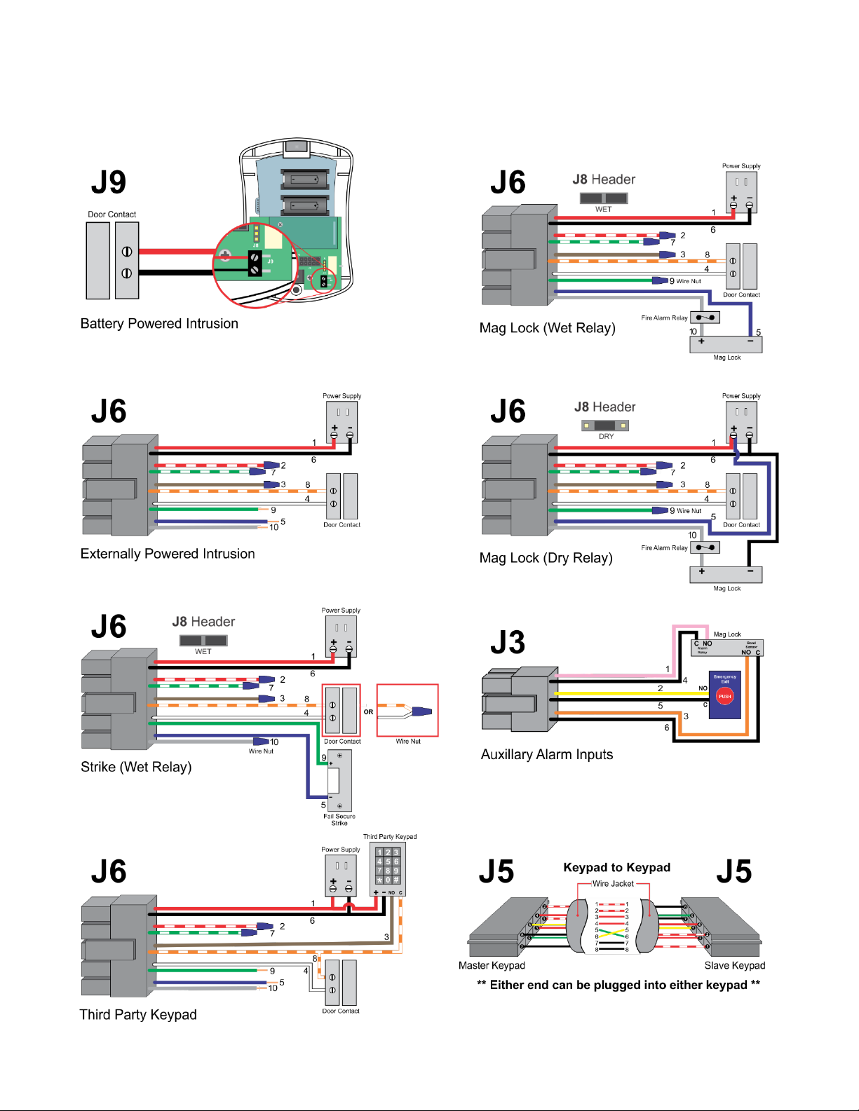
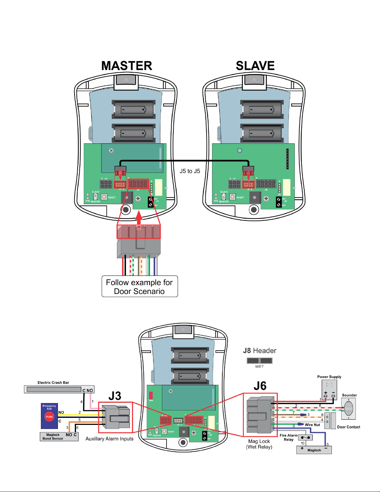
Auxiliary alarm inputs are available on the AIO Keypad that can be used to monitor the alarm
relays of various devices such as maglocks, bond sensors, and emergency exit buttons
(Stopper). When one of these auxiliary alarm inputs are activated the keypad will create an
alarm with audible and visual alarm indications. The alarms will clear when the input is
deactivated.
SW1 is a reed switch that can be used to detect a case tamper scenario. For case tamper
detection to work properly, a magnet installed on the backplate must be properly aligned with
SW2 is a pushbutton that can be used to reset the AIO Keypad or to send a reset signal over
the wireless Inovonics board to learn into an eCall or security system.
SW4. When the AIO Keypad enclosure is opened, the separation between the magnet and
SW4 will create a tamper condition. To clear the condition, the enclosure must be re-installed
bringing the magnet and SW1 back together.
The Request to Exit (REX) input on the keypad can be used to connect the keypad to 3rd
party systems or devices. An example of a REX device can be a 3rd party keypad, an access
control system, a push button, or a motion detector. A closure on the input will grant access
through the door or (if configured to) reset alarms.
Maintenance
Cleaning should be performed by hand using a damp cloth and mild soap, or disinfectant
wipes designed for household use. Ensure the keypad is fully dry prior to operating the unit.
Any moisture, dirt, or debris can cause erroneous button activations on the keypad.
Do Not Use the following products to clean the keypad:
• Strong cleaning agents such as ammonia, bleach, alcohol or quaternary disinfectant.
• Abrasive or powder cleansers.
• Alcohol-based hand sanitizers.
Test and clean the keypad weekly to ensure it is securely mounted and that all features are
working properly.
Battery Powered Keypad Testing
If operating the keypad from batteries, check the voltage of the batteries using a multimeter. If the
voltage of either battery drops below 2.8 volts, replace the battery. Once the voltage drops below 2.6
volts, the keypad will continually beep until the battery is replaced.
Enter the master code into the keypad (default is 1234). The keypad LED should turn green.
Open the door and hold it open. The propped door alarm should activate after 20 seconds.
Close the door. The propped door alarm should clear. Ensure propped door and clear messages
were received on the monitoring system.
Open the door without entering a code. The forced door alarm should activate immediately.
Enter the master code into the keypad (default is 1234). The forced door alarm should clear. Ensure
forced door and clear messages were received on the monitoring system.
6
Document # 106050 © 2019 PalatiumCare, Inc - Rev 1.3.3
External Powered Keypad Testing
If operating the keypad external power, the LED backlight should be on. Ensure that you see the
backlight turned on.
Enter the master code into the keypad (default is 1234). You should here a slight audible click from
the relay activating and the keypad LED should turn green. Ensure locking device unlocks the door.
Open the door and hold it open. The propped door alarm should activate after 20 seconds.
Close the door. The propped door alarm should clear. Ensure propped door and clear messages
were received on the monitoring system.
Open the door without entering a code. The forced door alarm should activate immediately.
Enter the master code into the keypad (default is 1234). The LED should turn green and the forced
door alarm should clear. Ensure forced door and clear messages were received on the monitoring
system.
Mounting Instructions
1. Determine the height that the device is to be mounted from floor to the top of the
device.
2. Make a small horizontal mark on the wall one inch lower than the top of the intended
height.
3. Install a single gang drywall box at this mark matching the top of the mark with the top
of the drywall box cutout.
4. Feed the needed wires into the drywall box and connect them to the proper pigtails.
Cap unused wires. See wiring diagrams and pigtail pinouts for further details.
5. Push the pigtail connectors through the wide oval hole in the mounting plate and mount
the top hole of the back plate onto the top hole of the single gang box with the included
screw.
6. Using a level on the side of back plate, make sure the back plate is level on the wall.
7. Screw the bottom of the mounting plate to the bottom hole of the single gang box.
8. Plug the pigtails into the AIO Keypad.
9. If powering the device from batteries, install two batteries into the keypad.
10.Learn keypad into the PalatiumCare system, and test to ensure it is functioning
properly.
11.Hang the AIO Keypad on the back plate.
12.Screw in bottom mounting screw until tight.
Caution: Over-tightening the housing screws can result in microcracks in the plastic and/or
stripping of the bushing. Any of these conditions can compromise the stability of the device as
well as future secure mounting.
7
Document # 106050 © 2019 PalatiumCare, Inc - Rev 1.3.3
Wiring Examples
All wiring splices should be made in approved junction boxes. Ensure all unused wires are
capped off with wire nuts.
8
Document # 106050 © 2019 PalatiumCare, Inc - Rev 1.3.3
Typical Wiring Door Scenarios
9
Document # 106050 © 2019 PalatiumCare, Inc - Rev 1.3.3
AIO Keypad Master and Slave Keypad Connections
Delayed Egress Controller Example
10
Document # 106050 © 2019 PalatiumCare, Inc - Rev 1.3.3
AIO Keypad (Wet Relay) with PalCare Delayed Egress Maglock Example
11
Document # 106050 © 2019 PalatiumCare, Inc - Rev 1.3.3
Connector Layout
Relay Jumper Config (J8)
By default, the keypad ships with the relay in “wet” mode with two jumpers on all four J8 pins.
By installing one jumper on the inner two pins, the relay can be switched to “dry” mode.
When the relay is in “dry” mode, it will function like a standard relay. When the relay is in
“wet” mode, the common wire (blue) becomes a ground or negative wire. The normally open
wire (green) becomes positive when the relay is activated. The normally closed wire (gray)
becomes positive when the relay is deactivated. You can directly connect a strike or maglock
to these wires. Please note: you must still follow all life safety codes when installing this
product, including the requirement to connect a fire alarm relay to deactivate mag locks in the
event of a fire.
12
Document # 106050 © 2019 PalatiumCare, Inc - Rev 1.3.3
Alarm Inputs (J3)
Input
Description
Maglock Alarm
Input used to monitor the alarm relay on the maglock. Will send
alarm information to the nurse call system when activated.
Stopper Alarm
Input used to monitor the emergency exit button near the door. Will
send alarm information to the nurse call system when activated.
Bond Sensor
Input used to monitor the bond sensor on the maglock. Will send
alarm information to the nurse call system if the maglock is not
securely locked when the door is supposed to be secure.
User Types
User
Notes
Master User
Can enter programming mode, granted access through the door, and can reset
alarms.
Access User
Granted access through the door only.
Toggle User
Disables the door security for a fixed amount of time. See Keypad
Configuration for changing the duration.
Reset User
Used to reset alarms only.
REX User
Tied to the REX input on J6 wiring harness. Used to grant access only by
default. Can be changed in Keypad Configuration to also be allowed to reset
alarms.
Master and Slave Keypads
The AIO Keypad supports two keypads, one on each side of the door connected together via
J5. Power is shared between keypads through this connection as well so only one side
needs to be powered. LEDs and alarms should be replicated on both keypads so the two
keypads should function as one.
One keypad must be set as a master and one must be set as a slave. If only one keypad is
being used, it must be set as master.
SW3 is used to configure the keypad’s mode. The keypad must be unpowered while changing
the master/slave setting. To set a keypad as master, SW3 must be in the down position. To
set a keypad as slave, SW3 must be in the up position.
The slave keypad will automatically download all configuration from the master, so no
programming is required on the slave.
If you are converting a master into a slave, the reset button (SW2) on the back of the keypad
must be pressed to clear the configuration on the keypad.
If you are using any of the external inputs (J3 and J6), they must be connected to the master
keypad.
Programming can be performed on either keypad and both keypads will be updated.
13
Document # 106050 © 2019 PalatiumCare, Inc - Rev 1.3.3
Scheduled Unlock
If you wish to unlock the door and keep it unlocked on a schedule, this can be achieved by
connecting a timer relay to the REX and REX Common wires. When the timer activates the
relay, the green LED should turn on and stay on as long as the timer keeps the relay
activated.
J9 Door Contact Input
If running the keypad on batteries only, you can use the dedicated door contact input (J9) for
the door contacts to avoid drilling a hole in the wall for the pigtail wires.
SW4 Tamper Input
If you wish to monitor when the keypad is opened or taken off the wall, you can install a
magnet on the backplate that lines up with SW4 on the keypad. You will then need to enable
Case Tamper Reporting (see programming section below) to enable the feature. Once
enabled, anytime the magnet moves away from the SW4 reed switch, the wireless transmitter
will send a tamper signal.
UL Requirements
• Units shall not impair operation of panic hardware mounted on door.
• Units shall not impair intended operation of an emergency exit.
• Not to be used without UL approved latching hardware.
• Units/Models are intended to be connected to UL Listed Equipment, not intended for Burglar
or Fire Alarm Initiating or Indicating Devices.
• Ambient Conditions - “For Indoor Use Only”.
• Wiring methods shall be in accordance with the National Electrical Code, ANSI/NFPA 70.
• This device complies with part 15 of FCC rules.
Operation is subject to following two conditions:
1. This device may not cause harmful interference.
2. This device must accept any interference received, including any interference that may
cause undesired operation. Changes or modifications not expressly approved by party
responsible for compliance could void user’s authority to operate equipment.
Programming the Keypad
Entering Programming Mode
The first step to changing the configuration of your AIO Keypad is to enter programming
mode. To do so, you must enter the following key sequence:
99 # Master Code (default is 1234)
Once the keypad is in programming mode, the keypad will flash the orange LED. You can
now change all of the configuration items below. When entering a configuration sequence,
the keypad will give one long beep if the sequence was successful. If the sequence failed,
you will receive two quick beeps. Once you are finished changing your configuration, you can
press the * key to exit programming.
14
Document # 106050 © 2019 PalatiumCare, Inc - Rev 1.3.3
Master User Code
The Master User code is used to grant access through the door, reset alarms, and enter
programming mode.
To change the master user code, enter the following sequence including the stars:
1 # New Code * New Code *
Access User Code
The Access User code is used to grant access through the door only. It will not reset alarms
or allow you to enter programming mode.
To change the access user code, enter the following sequence including the stars:
2 # New Code * New Code *
Toggle User Code
The Toggle User code is used to deactivate the keypad for an extended period of time. The
timeframe can be configured using the steps listed further in the manual. To deactivate the
keypad, enter the Toggle User code into the keypad. This will deactivate it for the full
duration. If at any time you need to reactivate the keypad before the duration has expired,
enter the Toggle User code again. Typical use scenarios is for loading dock doors when
deliveries come, moving people and furniture into and out of the building, and for main
entrances to be unlocked during the day.
To change the toggle user code, enter the following sequence including the stars:
3 # New Code * New Code *
Reset User Code
The Reset User code is used to reset alarms only. It will not grant access through the door or
allow you to enter programming mode.
To change the rest user code, enter the following sequence including the stars:
4 # New Code * New Code *
Relay Activation Mode
The relay reactivation mode configures when the keypad will deactivate the relay after access
is granted. With some locking devices like strikes and straight mag locks, you will want to
relock them as soon as the door is opened. With other locking devices like delayed egress
mag locks, you will want to relock them when the door is closed. A value of 0 deactivates the
relay when the door is opened. A value of 1 deactivates the relay when the door is closed.
The default value is 1.
To change the relay reactivation mode, enter the following sequence in programming mode:
10 # 2 # VALUE # **
Master User Unlock Timeout
The master user unlock timeout is the amount of time in seconds the relay is activated when
you enter the master user code. If the door is opened and closed quicker than the unlock
time, the keypad will return to a secure state when the door is closed. The value can be
between 1 and 255 seconds. The default value is 20.
To change the master user unlock timeout, enter the following sequence in programming
mode:
11 # VALUE # 0 # **
15
Document # 106050 © 2019 PalatiumCare, Inc - Rev 1.3.3
Access User Unlock Timeout
The access user unlock timeout is the amount of time in seconds the relay is activated when
you enter the access user code. If the door is opened and closed quicker than the unlock
time, the keypad will return to a secure state when the door is closed. The value can be
between 0 and 255 seconds. 0 disables the access user. The default value is 20.
To change the access user unlock timeout, enter the following sequence in programming
mode:
11 # VALUE # 1 # **
Propped Door Timer
The propped door timer is the amount of time in seconds that the door can be held open
before the keypad issues a propped door alarm. The value can be between 0 and 255
seconds. 0 disables the propped door alarm. The default value is 20.
To change the propped door timer, enter the following sequence in programming mode:
11 # VALUE # 2 # **
Toggle User Unlock Timeout
The toggle user unlock timeout is the amount of time in minutes that the keypad will be
disabled after entering the toggle user code. The value can be between 0 and 1440 minutes.
0 disables the toggle user. The default value is 720.
To change the toggle user unlock timeout, enter the following sequence in programming
mode:
11 # VALUE # 3 # **
Door Contact Debounce Timeout
The door contact debounce timeout is the amount of time in deciseconds (tenths of a second)
that the keypad will wait before it recognizes the door changing state between open and
closed. This is used when you have a closer that closes the door too fast and the door
immediately bounces open slightly. Adjusting this value can prevent a forced door alarm from
occurring in this scenario. The value can be between 1 and 99 deciseconds (0.1 to 9.9
seconds). The default value is 5.
To change the door contact debounce timeout, enter the following sequence in programming
mode:
11 # VALUE # 4 # **
Delayed Egress Timer
The AIO Keypad can function as a delayed egress controller. When changing the Egress
Timer to either 15 or 30 seconds, the Maglock Alarm Input becomes the delayed egress
initiation device. You will need to connect a Normally Open (NO) crashbar or similar imitation
device to this input to use this feature. The value can be set to 0, 15, or 30.
To change the delayed egress timer, enter the following sequence in programming mode:
11 # VALUE # 5 # **
Delayed Egress Nuisance Delay
When using the AIO Keypad as a delayed egress controller, you can set a nuisance delay to
prevent accidental activations of the delayed egress system. This value can be set to 0,1,2,
or 3 seconds.
To change the nuisance delay, enter the following sequence in programming mode:
11 # VALUE # 6 # **
16
Document # 106050 © 2019 PalatiumCare, Inc - Rev 1.3.3
Auxiliary Input Debounce Timers
When using the auxiliary inputs on the J3 wiring harness, a custom debounce can be set for
the inputs. This is useful when these inputs are connected to a maglock that momentarily
activates the inputs when they are powered up and then deactivates them. You can increase
the debounce to avoid these nuisance delays. The value can be between 1 and 99
deciseconds (0.1 to 9.9 seconds). The default value is 15.
11 # VALUE # 7 # **
Alarm Volume
The alarm volume is the sound level set for the buzzer when the keypad is in alarm. The
value can be between 0 and 9, with 9 being the loudest. 0 will make the alarm silent. The
default value is 9.
To change the alarm volume, enter the following sequence in programming mode:
30 # 0 # VALUE # **
Keypad Press Volume
The keypad press volume is the sound level set for the beep after any key is pressed on the
keypad. The value can be between 0 and 9, with 9 being the loudest. 0 will make the key
presses silent. The default value is 5.
To change the alarm volume, enter the following sequence in programming mode:
30 # 1 # VALUE # **
Auto Accept Code
The auto accept code feature allows the keypad to automatically accept the correct code
when entered. If this option is disabled, you must push * after you enter the code to the
keypad. This option is useful if you are using codes of different length or are trying to match
the functionality of a different manufacturer’s keypad in your facility. A value of 0 will not
require a * after the code. A value of 1 will require a * to be entered after the code. The
default value is 0.
To change the auto accept code feature, enter the following sequence in programming mode:
30 # 2 # VALUE # **
Change Case Tamper Reporting
The change case tamper reporting feature allow the keypad to report when it has been
removed from the wall. A value of 0 will disable case tamper reporting. A value of 1 will
enable case tamper reporting. The default value is 0.
To change the case tamper reporting, enter the following sequence in programming mode:
30 # 5 # VALUE # **
Change Keypad Backlight Level –Active
The change keypad backlight level –Active feature allows you to change the brightness of the
backlight LEDs when the keypad is active. The keypad goes into active mode when any key
on the keypad is pressed. Please note, the backlight will not turn on when the keypad is
running on battery power. The value can be between 0 and 9 with 9 being the brightest. 0
will make the backlight turn off. The default value is 9.
To change the keypad backlight level –active feature, enter the following sequence in
programming mode:
30 # 6 # VALUE # **
17
Document # 106050 © 2019 PalatiumCare, Inc - Rev 1.3.3
Change Keypad Backlight Level –Passive
The change keypad backlight level –Passive feature allows you to change the brightness of
the backlight LEDs when the keypad is passive. The keypad goes into passive mode after 10
seconds of no keys being pressed. Please note, the backlight will not turn on when the
keypad is running on battery power. The value can be between 0 and 9 with 9 being the
brightest. 0 will make the backlight turn off. The default value is 9.
To change the keypad backlight level –passive feature, enter the following sequence in
programming mode:
30 # 7 # VALUE # **
Change REX to Reset Alarms
The change REX to reset alarms feature allows you to configure the keypad to reset alarms
with the REX input. This is useful when you have a 3rd party keypad on the other side of the
door connected to the REX input and you want a valid code entry to reset the alarm. A value
of 0 will not allow the REX input to reset an alarm, only grant access through the door. A
value of 1 will allow the REX input to reset an alarm in addition to granting access throught he
door. The default setting is 1.
To change the REX to reset alarms feature, enter the following sequence in programming
mode:
30 # 8 # VALUE # **
Change Radio Monitoring
The change radio monitoring feature allows you to configure the keypad to poll the radio to
ensure the EN1941XS radio module is connected and responding to the keypad. If the radio
module is disconnected, not responding, or a different module is inserted the keypad will start
beeping and flashing the Radio Communication Error pattern until the problem is resolved. If
you are using the EN1941, you must disable radio monitoring. A value of 0 will stop the
keypad from polling for the radio module. A value of 1 will make the keypad poll for the radio
module. The default value is 1.
To change the radio monitor feature, enter the following sequence in programming mode:
30 # 9 # VALUE # **
Change User Code Length
The change user code length feature allows you to change the length of the user codes to
make them more secure. The value can be set between 4 and 6 digits. The default value is 4.
To change the radio monitor feature, enter the following sequence in programming mode:
32 # 4 # VALUE # **
Factory Default Keypad
The factory default keypad feature allows you to set all of the keypad’s configuration settings
back to factory defaults.
To change all of the settings to factory defaults, enter the following sequence in programming
mode:
46 # 00000 # 00000 # **
Learning in the Transmitter
The AIO Keypad is used as a location device in the PalatiumCare system. When learning in
the device, press the reset button (SW2) immediately after clicking the ready button on the UI.
18
Document # 106050 © 2019 PalatiumCare, Inc - Rev 1.3.3
Keypad Configuration Options
Key Presses
Summary
Default
Range
99 # VALUE
Enter Programming Mode using Master Code
1234
4 to 6 digits
1 # VALUE * VALUE *
Change Master User Code
1234
4 to 6 digits
2 # VALUE * VALUE *
Change Access User Code
4 to 6 digits
3 # VALUE * VALUE *
Change Toggle User Code
4 to 6 digits
4 # VALUE * VALUE *
Change Reset User Code
4 to 6 digits
10 # 2 # VALUE # **
Unlock relay re-arms when door opens or when
door closes
1 (closes)
0 to 1
0 = opens
1 = closes
11 # VALUE # 0 # **
Change Master User Unlock Time Seconds
20 seconds
1 to 255
11 # VALUE # 1 # **
Change Access User Unlock Time Seconds
20 seconds
0 to 255
0 = disabled
11 # VALUE # 2 # **
Change Propped Door Timer Seconds
20 seconds
0 to 255
0 = disabled
11 # VALUE # 3 # **
Change Toggle User Unlock Timeout Minutes
720 minutes
0 to 1440
0 = disabled
11 # VALUE # 4 # **
Change Door Contact Bounce Timeout
Deciseconds (Tenths of a second)
5 deciseconds
1 to 99
(1 to 99 tenths of a second)
11 # VALUE # 5 # **
Change Delayed Egress Timer
0 (disabled)
0, 15, or 30 seconds
11 # VALUE # 6 # **
Change Delayed Egress Nuisance Delay
3 seconds
0 to 3 seconds
11 # VALUE # 7 # **
Change Auxiliary Input Debounce Times
15 deciseconds
1 to 99
(1 to 99 tenths of a second)
30 # 0 # VALUE # **
Change Alarm Volume
9 volume
0 to 9
0 = mute
9 = loudest
30 # 1 # VALUE # **
Change Key Press Volume
9 volume
0 to 9
0 = mute
9 = loudest
30 # 2 # VALUE # **
Change * Press Requirement After Entering
User Code
0 (disabled)
0 to 1
0 = disabled
1 = enabled
30 # 5 # VALUE # **
Change Case Tamper Reporting
0 (disabled)
0 = disabled
1 = enabled
30 # 6 # VALUE # **
Change Key Back-light Brightness During Use
9 bright
0 to 9
0 = off
9 = brightest
30 # 7 # VALUE # **
Change Key Back-light Brightness During Idle
5 bright
0 to 9
0 = off
9 = brightest
30 # 8 # VALUE # **
Change REX to Reset Alarms
1 (enabled)
0 to 1
0 = disabled
1 = enabled
30 # 9 # VALUE # **
Change Radio Monitoring
1 (enabled)
0 to 1
0 = disabled
1 = enabled
32 # 4 # VALUE # **
Change User Code Length
4 digits
4 to 6
46 # 00000 # 00000 # **
Factory Reset Configuration
*
Exit Programming Mode
After a successful command, the keypad will give one long beep. If there is an error with the command, it will give two quick beeps.
19
Document # 106050 © 2019 PalatiumCare, Inc - Rev 1.3.3
Keypad LED and Buzzer Indications
Event
LED
Buzzer
Access Granted
Master code
Green LED ON until Master unlock
time expires or door closes
N/A
Access Granted
Secondary code
Green LED ON until Secondary
unlock time expires or door closes
N/A
Bad Code Entry
Flash Red LED
60ms ON, 60ms OFF
3 Beeps
60ms ON, 60ms OFF
Keypad Lockout
Yellow LED ON
3 Beeps
60ms ON, 60ms OFF
Door Open
N/A
N/A
Door Closed
Red LED ON (if powered from
external power supply)
N/A
Door Forced
Flash red LED continuously
250ms ON, 250ms OFF
Continuous beeps
250ms ON, 250ms OFF
Door Propped
(propped timeout expired)
Flash red LED continuously
100ms ON, 2000ms OFF
Continuous beeps
100ms ON, 2000ms OFF
Door Keypad Bypassed
(Toggle User Entered)
Flash green LED continuously
250ms ON, 250ms OFF
6 Beeps
60ms ON, 60ms OFF
Maglock Alarm
Flash red LED continuously
250ms ON, 250ms OFF
Continuous beeps
250ms ON, 250ms OFF
Stopper Alarm
Flash red LED continuously
250ms ON, 250ms OFF
Continuous beeps
250ms ON, 250ms OFF
Bond Sensor Alarm
Flash red LED continuously
250ms ON, 250ms OFF
Continuous beeps
250ms ON, 250ms OFF
Delayed Egress Nuisance Alert
Flash red LED continuously
300ms ON, 300ms OFF
Continuous ON
Delayed Egress Countdown
Alarm
Flash red LED continuously
700ms ON, 300ms OFF
Continuous beeps
700ms ON, 300ms OFF
Configuration Data Request
(including access codes)
Flash Red 250ms ON, 250ms OFF,
Flash Yellow 250ms ON, 250ms OFF,
Flash Green 250ms, 250ms OFF
N/A
Trouble Condition
Radio Module Communication
Error
Flash green and red LED
1x 200ms ON, 200ms OFF
5 second pause and then repeated
1x 200ms ON 200ms OFF beep
followed by 5 second pause and
then repeated
Trouble Condition
Primary and Secondary Unit
Communication Error
Flash green and red LED
2x 200ms ON, 200ms OFF
5 second pause and repeated
2x 200ms ON 200ms OFF beeps
followed by 5 second pause and
then repeated
Trouble Condition
Logic and Keypad Board
Communication Error
Flash green and red LED
3x 200ms ON, 200ms OFF
5 second pause and repeated
3x 200ms ON 200ms OFF beeps
followed by 5 second pause and
then repeated
Trouble Condition
Relay Activation Error
Flash green and red LED
4x 200ms ON, 200ms OFF
5 second pause and repeated
4x 200ms ON 200ms OFF beeps
followed by 5 second pause and
then repeated
Critically Low Battery
Flash red LED
5x 200ms ON, 200ms OFF
5 second pause and repeated
5x 200ms ON 200ms OFF beeps
followed by 5 second pause and
then repeated
Doorbell
Flash green LED
6x 60ms ON, 60ms OFF
6x Beeps
60ms ON, 60ms OFF
Send Configuration
Flash red, green, and orange LED
1x 200ms ON, 200ms OFF
Single beep
200ms ON, 200ms OFF
Factory Reset
Flash red LED 2000ms
Flash green and orange 1000ms
500ms OFF
Continuous beeps
1000ms ON, 1000ms OFF
20
Document # 106050 © 2019 PalatiumCare, Inc - Rev 1.3.3
Main Wiring Harness (J6) Pinout
(Front View)
PIN
Description
Wire Color
1
+VDC
Red
2
External Sounder + (100ma Max)
White/Red
3
REX
Brown
4
Door Contact
White
5
Relay Common (dry) or Ground (wet)
Blue
6
Ground
Black
7
External Sounder Ground
White/Green
8
REX / Door Contact Common
Orange/White
9
Relay Normally Open (dry) or +VDC NO (wet)
Green
10
Relay Normally Closed (dry) or + VDC NC (wet)
Gray
Secondary Wiring Harness (J3) Pinout
(Front View)
PIN
Description
Wire Color
1
Mag-lock Alarm
Pink
2
Mag-lock Stopper
Yellow
3
Bond Sensor
Orange
4
Ground
Black
5
Ground
Black
6
Ground
Black

This manual suits for next models

2

Popular Keypad manuals by other brands

WEG HMI-03 user manual

WEG

WEG HMI-03 user manual

Visonic CL-80 installation instructions

Visonic

Visonic CL-80 installation instructions

Think PINPAD user guide

Think

Think PINPAD user guide

SECO-LARM ENFORCER SK-3523-SDQ manual

SECO-LARM

SECO-LARM ENFORCER SK-3523-SDQ manual

United Technologies interlogix ACL805SUW-RDMF installation manual

United Technologies

United Technologies interlogix ACL805SUW-RDMF installation manual

Verex Monitor XL user guide

Verex

Verex Monitor XL user guide

Proteco RT37 quick start guide

Proteco

Proteco RT37 quick start guide

Essex Electronics K1 Series Installation instructions manual

Essex Electronics

Essex Electronics K1 Series Installation instructions manual

AC Tech SCF SERIES instructions

AC Tech

AC Tech SCF SERIES instructions

Macally BTCALKEY user guide

Macally

Macally BTCALKEY user guide

Texas Instruments TCA8418E user guide

Texas Instruments

Texas Instruments TCA8418E user guide

SEW-Eurodrive MOVITRAC B operating instructions

SEW-Eurodrive

SEW-Eurodrive MOVITRAC B operating instructions

Lutron Electronics seeTouch QS Application note

Lutron Electronics

Lutron Electronics seeTouch QS Application note

Pyronix STERLING 10 installation instructions

Pyronix

Pyronix STERLING 10 installation instructions

BFT Q.BO Touch installation manual

BFT

BFT Q.BO Touch installation manual

AMX Novara SP-08-E-US instruction manual

AMX

AMX Novara SP-08-E-US instruction manual

Potter RA-7690 Installation sheet

Potter

Potter RA-7690 Installation sheet

NAPCO GEM-K1VPS operating guide

NAPCO

NAPCO GEM-K1VPS operating guide

manuals.online logo
manuals.online logoBrands
  • About & Mission
  • Contact us
  • Privacy Policy
  • Terms and Conditions

Copyright 2025 Manuals.Online. All Rights Reserved.