Larisch 98-572_99-04_00-03.doc K7957, 17.11.2009
4. Installing the electrical system
1. Use the corresponding MBB circuit diagram accommodated in the sealing cap on the right-hand side
(direction of travel) and observe the vehicle manufacturer's assembly instructions.
2. Run the battery cable to the battery, shorten it if required and connect the cable lug.
3. Assemble the main fuse with the cable lug and connect it to the battery positive terminal.
4. Run the control box cable to the driver's cab, select the appropriate place at the instrument panel,
establish an electrical connection according to the MBB circuit diagram and attach the control box.
5. If a control box is already present in the vehicle, connect the MBB tail lift according to the additional
MBB circuit diagram. If required, order this circuit diagram from MBB.
6. Establish a ground connection according to the vehicle manufacturer's assembly instructions.
7. NOTICE! For DGRTR vehicles, connect the ground cable to the battery or according to the vehicle
manufacturer's assembly instructions.
8. Fasten the operating panel with screws or weld it acc. to the MBB assembly drawing.
9. When installing the hand cable control, observe the following: Install the cable with terminal box
under the truck platform in such a way that the cable can be connected to the hand cable control
from there. Connect the hand cable control cable to the terminal box as specified in the MBB circuit
diagram. Select a suitable and safe accommodation for the hand cable control.
10. The hand cable control may be operated from the marked position on the platform, only.
6. Mounting and adjusting the tilt cylinder
1. Remove the screw plug of the oil reservoir and replace it with the attached air filter (if existing).
2. Turn both rod heads of the tilt cylinders until reaching the piston rod stop. Actuate the Fold in and
Fold out rotary switches to set the tilt cylinder to a length that allows you to connect the cylinders to
the tailboard using bolts.
Note! First bolt only one cylinder to the tailboard.
3. Move up the lifting device using the lift cylinders until reaching the top end stop and dismount the
auxiliary unit.
4. Attach the tilt sensor to the platform as shown.
5. Lower the platform until reaching the ground, fold the platform head and then raise the platform
package with the bolted cylinder to such an extent that the extended tilt cylinder gets in contact with
the inner stop.
Turn the tilt cylinder's piston rod using a spanner until the platform is at an angle of around 75° to
the ground. Then tighten it with a counter nut towards the rod head.
Also move the other tilt cylinder to the inner stop and turn its piston rod to allow for bolting it. Secure
the rod head using a counter nut.
6. Swivel down and raise again the platform package several times. If the lifting device should be lifted
when raising, evenly turn in the piston rods into the rod head.
This reduces the angle between the platform and the ground and, thus, the tilt angle for lifting the
lifting device.
7. Tighten the counter nut and mount the bellows.
8. Attach the end position switches to the vehicle chassis frame in such a way that the pilot lamps of
the control box are off when the platform is in the vehicle driving position.
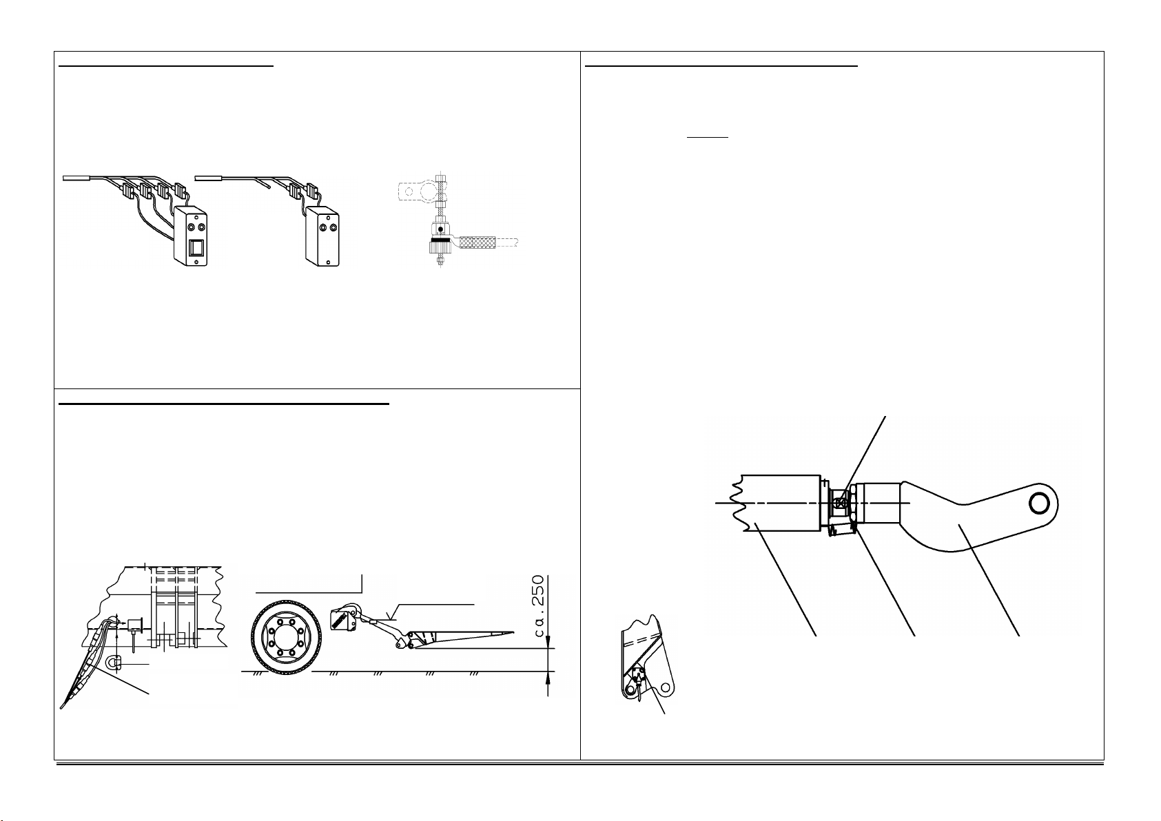
5. Adjusting and mounting prior to commissioning
1. Raise the platform until reaching the stop.
2. Take the three connectors for the foot control (not with Basic) and Warnfix out of the platform,
connect them to the connectors coming from the lift arm (yellow cable binders with yellow cable,
black with black and connector marked with white cable binders), return the connectors connected in
this way to the platform and install the strain relief.
3. Securely fasten the cables to the lift arm using cable binders. Make sure that the platform can move
freely, provide sufficient cable length.
4. Make sure that all installed cables have been laid thoroughly and fastened reliably. Observe the
required bending lengths.
5. Lower the platform until reaching a level of approx. 250 mm above ground and set the switch b13 at
the right lift arm to its horizontal position. For this purpose, undo the switch fastening screw, re-
tighten it after the setup and fold back the locking plate.
6. Lift, lower, fold in and fold out the platform several times in order to deaerate the cylinders.
7. Check the oil level with lowered platform and check that all screw connections made according to the
MBB assembly drawing are tight. Perform an acceptance test according to the MBB test data
booklet and record the test results in the test data booklet.
Control box for
motor vehicles
Control box for
semitrailers or
trailers
Plug for foot
control and Warnfix
Switch b13
Locking plate
horizontal
Install sensor b15 in this way


