Trademarks & Intellectual Property
Pall and are trademarks of Pall Corporation.
Filtration. Separation. Solution. is a trademark of
Pall Corporation.
Copyright
The design of this equipment and all associated
documentation is copyright of Pall Corporation, 2018.
Reprints, even of extracts hereof, are permitted only if the
source is quoted and permission has been granted by Pall.
The main components, devices, arrangements, as well as
software, control and instrumentation equipment on all of
our machines are protected both at home and abroad by
patent applications, design registrations or copyright.
© Copyright
Pall Corporation
25 Harbor Park Drive
Port Washington, NY 11050
Connecting Utilities
To ensure the safe and efcient operation
of the equipment and adherence to
existing laws and regulations, only qualied
personnel should make utility connections.
Pall Corporation is not responsible for and
equipment warranties may be voided from
any damage or personal injury caused by
unqualied personnel performing utility
connections and/or installations.
Certications & Statements
FCC Statement
The Wi-Fi Gateway, Fluid Interface, and
Filter Housing comply with Part 15 of the
FCC Rules. Operation is subject to the
following two conditions: (1) these devices
may not cause harmful interference, and (2)
these devices must accept any interference
received, including interference that may
cause undesired operation.
These devices do not contain any user-
serviceable parts. Changes or modications
not expressly approved by Pall Corporation
could void the user’s authority to operate
the equipment.
Note: This equipment has been tested and
found to comply with the limits for a Class
A digital device, pursuant to part 15 of
the FCC Rules. These limits are designed
to provide reasonable protection against
harmful interference when the equipment
is operated in a commercial environment.
This equipment generates, uses, and can
radiate radio frequency (RF) energy and, if
not installed and used in accordance with
the instruction manual, may cause harmful
interference to radio communications.
Operation of this equipment in a residential
area is likely to cause harmful interference
in which case the user will be required to
correct the interference at his own expense.
These devices use RF energy to
communicate. To reduce RF Exposure,
these devices must be installed in a manner
to ensure at least 20cm separation is
maintained between the device antenna
and the body of the user or nearby people.
ISED (Canada) Notice
These devices comply with Industry
Canada’s license-exempt RSSs. Operation
is subject to the following two conditions:
(1) these devices may not cause harmful
interference, and (2) these devices must
accept any interference received, including
interference that may cause undesired
operation.
CE (Europe) Notice
Hereby, Pall Corporation declares that
these devices are in compliance with the
essential requirements and other relevant
provisions of Directive 2014/53/EU.
UL Certication Statement:
Underwriters Laboratories has tested and
evaluated the Athalon®CM Gateway, Fluid
Interface and Filter Node(s) as Control and
Measuring Equipment and has issued a
Certicate of Compliance to:
•UL 61010-1, 3rd Edition, May 11, 2012,
revised April 29, 2016
•CAN/CSA-C22.2 No. 61010-1-12,
3rd Edition, revision dated April 2016
Reference Certicate No. 2017-8-25-
E479541 and Report E479541-D1000-1/
A0/C0-UL date 25 August 2017.
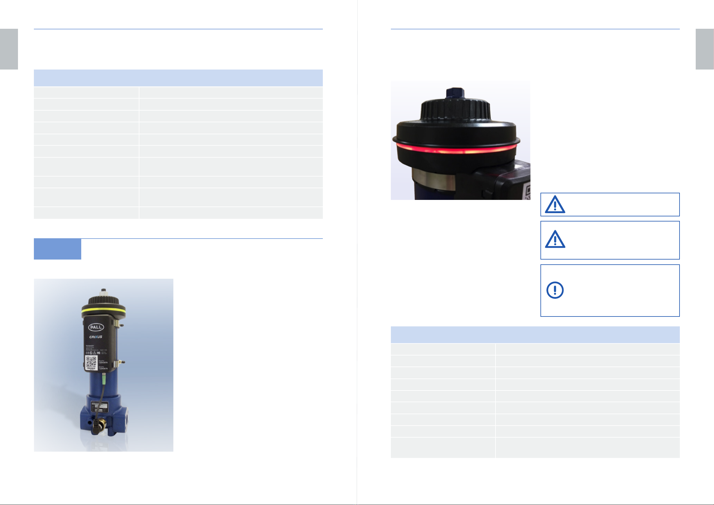
Athalon®CM User Manual
To ensure the safety of personnel during the
installation and operation of the Athalon®CM
system, the following symbols will help
identify important information regarding the
equipment.
WARNING:
These are instructions that draw
attention to the risk of injury or
death!
CAUTION:
These are instructions that draw
attention to the risk of damage
to the product, the process, the
equipment or the surroundings!
IMPORTANT:
These are instructions that draw
attention to information that will
aid installation, operation or
maintenance!
WARNING - ELECTRICAL HAZARD:
These are instructions that draw
attention to any potential
electrical hazards that could injure
personnel, the process or the
equipment!
Terms of Guarantee
The manufacturer is not liable for damage resulting
from: improper use, failure to observe this manual,
the employment of insufciently qualied personnel,
or unauthorised modications to the unit and unit
components supplied by Pall. In these cases the
manufacturer’s warranty / guarantee is rendered void.
CAUTION - IMPAIRMENT OF CORRECT
UNIT OPERATION WHEN USING
INCORRECT SPARE PARTS!
When using components that have not been approved,
correct operation of the unit can no longer be guaranteed.
Only use spare parts approved by Pall.
ENSURE THERE IS ADEQUATE
LIGHTING TO OPERATE EQUIPMENT.
OBSERVE LOCAL REGULATIONS FOR
FACTORY USE.
HEALTH AND SAFETY.
OBSERVE CAUTION WHEN HANDLING
FLUIDS AND PAY ATTENTION TO
INSTRUCTIONS OF SAFE USE IN THE
MATERIAL SAFETY DATA SHEET
AND COSHH REGULATIONS. WEAR
PROTECTIVE CLOTHING IF
PRESCRIBED; E.G. SAFETY GLOVES,
CLOTHING AND FOOTWEAR.
BE AWARE OF POSSIBLE DANGER
ASSOCIATED WITH HIGH OIL
TEMPERATURES AND EXPOSED METAL
SURFACES OF THE ATHALON®CM
HARDWARE.
DO NOT USE THE ATHALON®CM
HARDWARE IN AN EXPLOSIVE
ATMOSPHERE.
WARNING - ELECTRICAL HAZARD