Pall UR209 Series Operating instructions

service instructions
UR209
UR209 Series
1372872 IM SI UR209
EN
UR209 Service Instructions
ENGLISH

1 Specifications
Housing materials:
Head: Die cast aluminium alloy, painted
external surface (as standard)
Bowl: Die cast aluminium alloy, painted
external surface (as standard)
Bypass Valve: Polyamide poppet, Steel seat
and spring
Maximum operating pressure:
41 bar (600 psi)
Rated burst pressure:
113 bar (1650 psi)
Element burst pressure:
UE209 element 10 bard (150 psid) differential minimum
Operating temperature range:
-29°C to 120°C (-20°F to 250°F) with fluorocarbon seals for
petroleum based and specified synthetic fluids
60°C (140°F) maximum in HWCF, water-oil emulsion
or water glycol
Bypass valve setting options:
1.7 ± 0.3 bard (25 ± 5 psid) cracking pressure
4.5 ± 0.3 bard (65 ± 5 psid) cracking pressure
Non bypass
Seals:
Fluorocarbon
The actual operating conditions should be checked by the user
to ensure that the element, housing and all seals are
compatible with the fluid and application, and are within local
safety codes. Please contact Pall or an approved Pall
distributor if further information is required.
2 Receipt of equipment
The filter housing, and any optional equipment, are packed
individually for assembly by the customer. Unpack carefully
and ensure optional items are not mislaid in packaging to be
discarded.
3 General sources of information
3.1 For dimensions, operating parameters,
assembly/element part number, ordering information,
notes, performance data and specifications refer to
datasheet IMUR209EN.
3.2 This equipment has been assessed in accordance with
the guidelines laid down in the European Pressure
Directive 97/23/EC and has been classified within sound
engineering practice S.E.P. We hereby declare the
equipment meets the requirements of article 3, section
3, thus meeting the directive requirements. Under the
provisions of this directive the filter assembly is suitable
for use with group 2 fluids only.
3.3 Where under reasonably foreseeable conditions,
including external fires, the allowable limits could be
exceeded, suitable protective devices must be installed
by the customer within the connecting fluid system.
4 Installation of housing
4.1 The filter can be installed in any attitude, but for ease of
servicing, it is recommended that it be installed vertically
with the filter bowl pointing downwards.
4.2 The minimum clearance required for element removal
is 69 mm (2.7") for all lengths.
4.3 The UR209 series housing is supplied without a filter
element. For element installation and servicing
procedures, refer to Section 7.
NOTE: The UR209 head is supplied with one machined
differential pressure warning port fitted with a plastic shipping
plug. If a differential pressure warning device is to be fitted,
the plastic shipping plug should be removed and replaced by
a visual or electrical warning device, torque tightened to
14 Nm (10 ft/lb).
4.4 Mount the filter assembly in position using four 3/8-16
('A' and 'B' ports) or M10 x 1.5 ('C' ports) bolts in
the holes on the head mounting pads. Torque bolts to
12-26 Nm (9-19 ft/lb).
4.5 Use a check valve downstream of the filter if there is a
possibility of reverse flow.
4.6 Install the filter housing using additional piping/valving
to allow complete filter assembly bypass if filter
maintenance is required without system shutdown.
This series is not available in a duplex or service
bypass configuration.
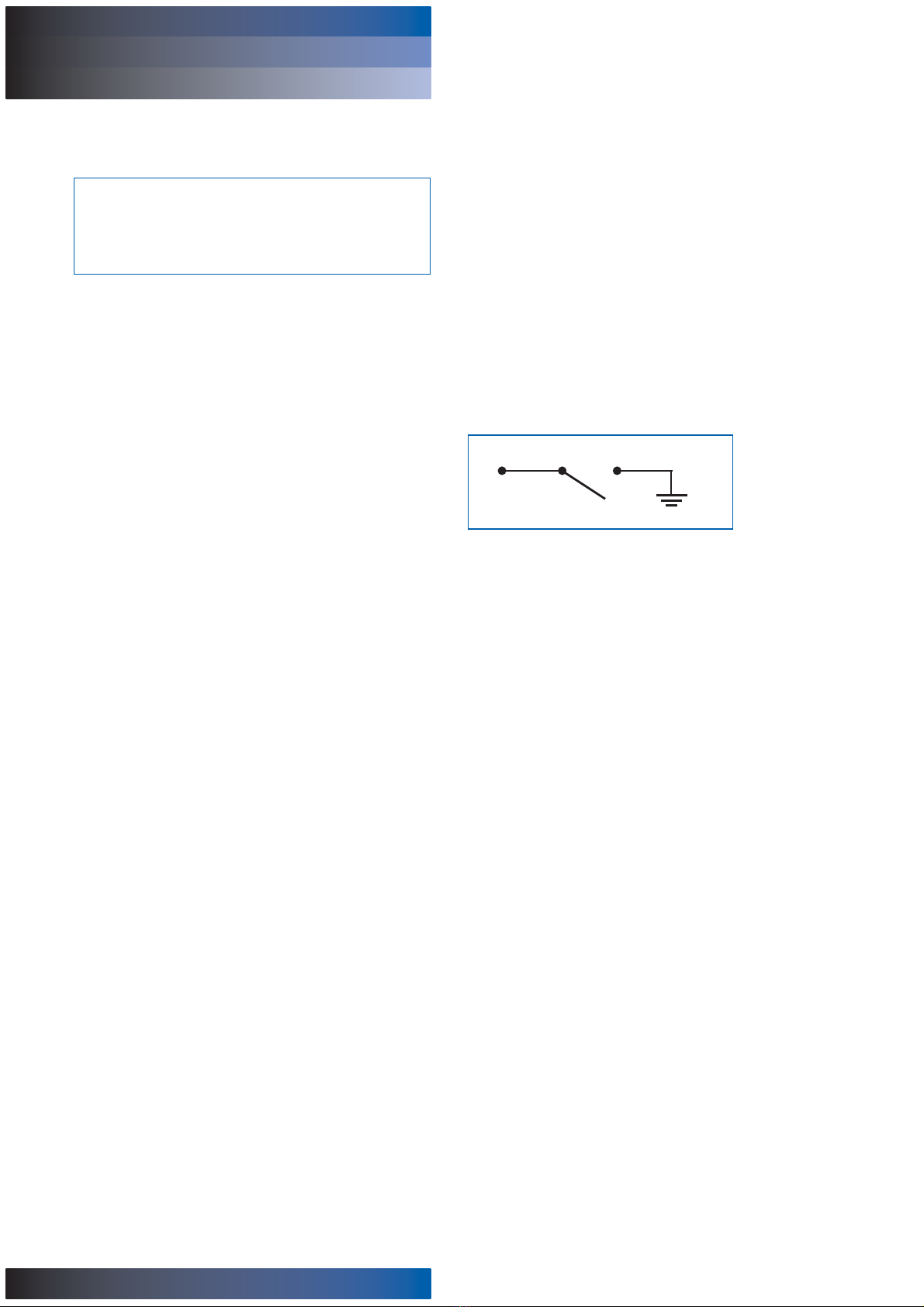
NOTE: Piping supports should be provided as close as is
practicable to the port connections in order to minimize
external loads. This filter assembly must not be electronically
isolated from the users earthing system. This filter assembly
must be earthed by connecting the users earthing system to
one of the inlet/outlet connections.
4.7 Connect lines or hoses to housing inlet and outlet ports.
NOTE: Painting of the filter housing is optional. The coating on
the filter housing is a suitable painting base. Cover the
differential pressure warning device and nameplate if painting
of the housing takes place.
CAUTION:
Maximum surge flow should not exceed 1.3 times
normal flow.
WARNING:
USE FITTINGS OR ADAPTORS COMPATIBLE WITH
PORTS SUPPLIED AS SHOWN BY PART NUMBER ON
NAMEPLATE AND NOTED IN DATA SHEETS: USE OF
INCORRECT FITTINGS OR ADAPTORS CAN CAUSE
FILTER HOUSING OR MANIFOLD FAILURE
RESULTING IN LOSS OF PRESSURE AND POSSIBLE
SYSTEM FAILURE OR PERSONAL INJURY.
CAUTION:
Reverse flow through filter element will cause damage.
UR209 UR209 Series
RETURN LINE FILTERS service instructions
1
CAUTION:
Do not operate the filter unless the warning device port
is sealed.

4.8 Jog system and fill filter. Pressurize system fully and
check for leaks; if leaks occur refer to Section 5.
5 Routine maintenance
5.1 Pall filters do not normally require special attention
except for periodic monitoring of the differential pressure
warning device. Schedule replacement of filter element
every six months or sooner, and have ample supply of
spare elements available.
5.2 If external leakage is noted, replace O-ring at leak. If
leakage persists, check sealing surfaces for scratches or
cracks; replace any defective parts.
5.3 Differential pressure devices actuate when the element
needs changing or because of high fluid viscosity in
'cold start' conditions. If 'cold start' conditions exist, see
Section 6.2 and 6.3.
5.4 A dirty system can quickly plug a new filter element,
especially with Pall high efficiency filter media. It may
require one or two initial element changes to stabilize
element life. If element life is short or differential
pressure is excessive, filter may be undersized; refer to
the sizing and selection section of the product literature
or contact your local Pall representative.
5.5 Make sure element change labels are clean and
undamaged. Replace illegible labels with the appropriate
new labels.
6 Differential Pressure Devices
Reference should be made to product literature for dimensions,
operating parameters, part numbering, ordering information
and specifications.
6.1 Differential pressure devices actuate when the element
needs changing or because of high fluid viscosity in
'cold start' conditions.
6.2 If the differential pressure switch actuates during cold
start, continue operating until the signal goes out as
system warms to normal operating temperature. This
feature can be used as 'warm up' indication in operating
procedures. If the warning signal remains or appears
when system is warm, replace the filter element.
6.3 Use of both positive indication and negative indication is
recommended to effectively monitor filter element life.
NOTE: These electrical and visual Differential pressure
devices (respectively, F5 and FD series) are very specific
to the UR209 series.
Electrical connections and ratings for F5 code electrical
pressure switch options:
28 VDC = 3A (inductive),
5A (resistive)
Amperage: 200mA maximum
Circuit:
SPST Normally open circuit
Ground through filter assembly
to chassis
CAUTION:
Failure to bleed the filter housing adequately will
increase the dissolved air content of the system fluid
which will shorten fluid life and may cause other
problems in the system.
UR209 UR209 Series
RETURN LINE FILTERS service instructions
2
Figure 1 - Switch Circuit Diagram

7 Filter element servicing
During servicing, the external surfaces of the filter assembly
must be cleaned to remove any dust deposits.
Servicing must be conducted using suitable tools that do not
present a hazard.
Servicing must not be carried out when a potentially explosive
atmosphere is present.
Refer to Service Parts List (Section 10) for item numbers for
applicable replacement element series. Remove and replace
element as follows:
7.1 Turn off and depressurize the system.
7.2 Unscrew and remove filter bowl (2) from head assembly
(1), anti-clockwise when viewed from below. It maybe
necessary to use a 1" socket wrench on the hexagon to
loosen the bowl initially.
7.3 Drain fluid from the bowl into a suitable waste container.
7.4 Element replacement (UE209 Series): Remove filter
element (5) by turning clockwise (when viewed from
below) and gently pulling the element from the filter
head (1). Carefully inspect the interior surface
(flow through the element is in-to-out) for visible
contamination. Normally no dirt should show, but visible
dirt or particles can be an early warning of system
component failure. Discard both the filter element and
its O-ring. The filter element is NOT CLEANABLE.
Any attempt to clean the filter element can cause
degradation of the filter medium and allow contaminated
fluid to pass through the filter element.
7.5 DO NOT run the system without a filter element
installed. Check that the O-ring (3) between the head (1)
and bowl (2) is not damaged. Use the replacement filter
as indicated by the part number on the element endcap.
7.6 Lubricate element O-ring with clean system fluid.
Reinstall element in the filter head (1) by engaging
element and turning anti-clockwise until the element
tabs lock into the filter head. Lightly lubricate head-to
bowl O-ring with clean system fluid and reassemble the
until thread bottoms. Hand tighten only. O-ring sealing is
not improved by over tightening
7.7 Bleed the system and check for leaks as per
section 4.8.
7.8 After element change, ENSURE VISUAL INDICATOR IS
RESET BY PUSHING IN THE RED BUTTON. Electrical
differential pressure devices will reset automatically.
When system reaches normal operating temperature,
check that the switch has not actuated and/or the visual
warning button has remained depressed. If visual
indicator rises due to a cold start condition, reset again
as per section 6.
8 Fluid sampling
Optimum sampling to verify fluid condition can be achieved by
the use of sampling adaptors installed on the hydraulic system
itself. For more information consult Pall or your local Pall
distributor. Pall offers a fluid contamination analysis service -
consult the Pall sales office.
9 Warranty, Limitation of Liability
and Remedies
THERE IS NO WARRANTY OF MERCHANTABILITY OR
FITNESS FOR ANY PARTICULAR PURPOSE WITH RESPECT
TO ANY OF THE PRODUCTS, NOR IS THERE ANY OTHER
WARRANTY EXPRESS OR IMPLIED, EXCEPT AS PROVIDED
FOR HEREIN.
For a period of twelve months from the date of delivery from
Seller or three thousand hours of use, whichever occurs first
(the "Warranty Period"), Seller warrants that products
manufactured by Seller when properly installed and
maintained, and operated at ratings, specifications and design
conditions, will be free from defects in material and
workmanship. By way of explanation and not limitation, the
Seller does not warrant the service life of the filter element as
this is beyond the Seller's control and depends upon the
condition of the system into which the filter is installed.
CAUTION:
Filter elements should be replaced upon indication
or at specified intervals, six months maximum.
Failure to change the element will cause the filter to
go on bypass.
WARNING:
FAILURE TO DEPRESSURISE THE FILTER BEFORE
SERVICING ELEMENT COULD RESULT IN
EXPLOSIVE LOSS OF FLUID, DAMAGE TO
EQUIPMENT AND POSSIBLE PERSONAL INJURY.
UR209 UR209 Series
RETURN LINE FILTERS service instructions
3
WARNING:
DO NOT ATTEMPT TO CLEAN OR RE-USE
THE ELEMENT.
ONLY USE GENUINE PALL REPLACEMENT FILTER
ELEMENTS. USE OF SUBSTITUTE ELEMENTS MAY
INVALIDATE PRODUCT WARRANTY.

UR209 UR209 Series
RETURN LINE FILTERS service instructions
4
ENGLISH
Seller's liability under any warranty is limited solely (in Seller's
discretion) to replacing (FOB original ship point), repairing or
issuing credit for products that become defective during the
Warranty Period. Purchaser shall notify Seller promptly in
writing of any claims and provide Seller with an opportunity to
inspect and test the product claimed to be defective. Buyer
shall provide Seller with a copy of the original invoice for the
product, and prepay all freight charges to return any products
to Seller's factory, or other facility designated by Seller. All
claims must be accompanied by full particulars, including
system operating conditions, if applicable.
Seller shall not be liable for any product altered outside of the
Seller's factory except by Seller or Seller's authorized
distributor, and then, as to the latter, only for products which
have been assembled by the distributor in accordance with
Seller's written instructions. Nor shall Seller be liable for a
product subjected to misuse, abuse, improper installation,
application, operation, maintenance or repair, alteration,
accident or negligence in use, storage transportation or
handling.
In no event will Seller be liable for any damages, incidental,
consequential or otherwise, whether arising out of or in
connection with the manufacture, packaging, delivery, storage,
use, misuse, or non use of any of its products or any other
cause whatsoever.
10 Parts List
List Description Catalog Number Quantity
1 Filter Head 1
2Bowl 1
3O-ring (head-to-bowl) UR209SKZ 1
Seal Kit (fluorocarbon)
4Indicator or port plug kit (not shown) See product literature 1
FD series:
Visual, 16 psid, Fluorocarbon 1375888
Visual, 50 psid, Fluorocarbon 1382233
F5 series:
Electrical, 16 psid, Fluorocarbon 1375887
Electrical, 50 psid, Fluorocarbon 1379743
FB series:
Blanking plug, Fluorocarbon 1373772
5 Filter element UE209**++Z
See product literature 1

UR209 UR209 Series
service instructions
5
2
4
5
Figure 1
Refer to product literature
3
1
Not shown
on this diagram
Inlet
RETURN LINE FILTERS

UR209 UR209 Series
service instructions
6
RETURN LINE FILTERS

UR209 UR209 Series
service instructions
Because of developments in technology these data or procedures may be subject to change. Consequently
we advise users to review their continuing validity annually. Part numbers quoted above are protected by the
Copyright of Pall Europe Limited.
, Pall and Ultipleat are trademarks of Pall Corporation.
Filtration. Separation. Solution is a service mark of Pall Corporation.
® indicates a trademark registered in the USA.
© Copyright 2008, Pall Corporation.
May 2008. Printed in England. IMSIUR209
Visit us on the web at www.pall.com
Pall Corporation has offices and plants throughout the world in locations including:
Argentina, Australia, Austria, Belgium, Brazil, Canada, China, France, Germany, India, Indonesia,
Ireland, Italy, Japan, Korea, Malaysia, Mexico, the Netherlands, New Zealand, Norway, Poland,
Puerto Rico, Russia, Singapore, South Africa, Spain, Sweden, Switzerland, Taiwan, Thailand,
United Arab Emirates, United Kingdom, United States, and Venezuela. Distributors are located
in all major industrial areas of the world.
Pall Industrial Manufacturing
New York - USA
+1 888 333 7255 toll free
+1 516 484 3600 telephone
+1 516 484 6247 fax
Portsmouth - UK
+44 (0)23 9230 3303 telephone
+44 (0)23 9230 2507 fax
RETURN LINE FILTERS
Table of contents
Other Pall Industrial Equipment manuals