Pall DU005-US User manual

Document #: 4100022 Revision: F Page #: 1 of 21
Pall Life Sciences. USA: Port Washington, NY, USA 1 800 717 7255 toll free (USA),+1 516 484 5400 phone,
LifeSciences.EU@pall.com e-mail. Asia-Pacific : +65 6389 6500 phone, sgcustomerservice@pall.com e-mail
© 2012, Pall Corporation. Pall, Allegro, Kleenpak, Stax and the Allegro Design are trademarks of Pall Corporation. ®
indicates a trademark registered in the USA and TM indicates a common law trademark.
Filtration.Separation.Solution is a service mark of Pall Corporation.
Magnetic Mixer
Single-Use Mixing System
OPERATOR MANUAL
DU005-US, DU006-EU, DU006-UK, DU006-SW, DU006-JP,
DU006-AU
USD 3185

Document #: 4100022 Revision: F Page #: 2 of 21
Safeguards and Precautions
1. Read and follow all instructions in this manual carefully, and retain this manual for
future reference. Operation manual can be provided electronically in alternate languages
upon request.
2. Do not use this instrument in any manner inconsistent with these operating
instructions or under any conditions that exceed the environmental specifications stated.
3. Do not plug the drive unit of the mixer in before verifying voltage configuration.
4. Use caution when lifting the equipment: Hold equipment by the frame and not by the
motor. Lifting may require more than one person.
5. Prior to servicing the drive unit, always turn the power off using the ON/OFF switch on
the front of the unit. Unplug and remove power cord to avoid tangling or breaking.
6. Do not attempt to open or repair the drive. Removal or destruction of the housing
voids any warranty, explicit or implied. Consult the manufacturer or distributor for
qualified technical service assistance.
7. Each mixing bag contains a magnetic impeller, which is the source of a strong
magnetic field in close vicinity (12 inches) of the impeller. PEOPLE USING ANY
ELECTRONIC MEDICAL DEVISES, SUCH AS PACEMAKERS, SHOULD NOT BE
INVLOVED IN THE CLOSE HANDLING OF MIXING BAGS, IMPELLERS OR TEST
IMPELLERS and should also be cautious when in close vicinity to the mixing head of the
drive unit.
8. Keep supplied magnetic shells on bags, magnetic shields on magnetic chargers, and
on impellers when not in use
9. DO NOT attempt to mix in empty or dry bags - it may result in to damage of the film of
the bag.
DO NOT submerge drive unit in water
DO NOT cut ground plug
CAUTION Disconnect all power before servicing
WARNING Risk of Electric Shock

Document #: 4100022 Revision: F Page #: 3 of 21
CAUTION Disconnection of the Protective Earth Connector may impair the protection
provided by the system
ATTENTION Mains outlet used to power the equipment must be within 3 meters of the
device and easily accessible
EXPLANATION OF SYMBOLS
WEEE: Waste of Electrical and Electronic Equipment
HIGH VOLTAGE
CAUTION
PROTECTIVE EARTH: Ground
MAIN POWER SWITCH
CE CERTIFIED (230V UNITS ONLY)

Document #: 4100022 Revision: F Page #: 4 of 21
1. TABLE OF CONTENTS
1. TABLE OF CONTENTS...........................................................................................4
2. SPECIFICATIONS ...................................................................................................5
3. INTRODUCTION & PRINCIPLE OF OPERATION..................................................5
4. ELECTRICAL SCHEMATIC.....................................................................................6
5. MAGNETIC MIXER SYSTEM COMPONENTS........................................................8
6. MAGNETIC MIXER SYSTEM ACCESSORIES .......................................................9
7. DOLLY - TANK ASSEMBLY .................................................................................11
8. BAG - INTERFACE ASSEMBLY...........................................................................12
9. INSERTING PLASTIC BAG INTO TANK ..............................................................13
10. COUPLING THE BAG WITH THE DRIVE UNIT....................................................14
11. DRIVE MOTOR OPERATION................................................................................15
12. DISCONNECTING DRIVE UNIT FROM TANK......................................................16
13. EZD OPERATING INSTRUCTIONS ......................................................................17
14. ATMI LIFESCIENCES - SERVICE.........................................................................19
15. SPARE PARTS......................................................................................................19
16. DECLARATION OF CONFORMITY ...............ERROR! BOOKMARK NOT
DEFINED.

Document #: 4100022 Revision: F Page #: 5 of 21
2. SPECIFICATIONS
Power:
Single Phase 115/230V AC 50/60 Hz, full load current 2.0/1.0 A
Input Wattage:
Less than 180 Watts at maximum speed
Speed Range
0-300 RPM
Degree of Protection:
NEMA 4X, IP 65
Altitude
Up to 1000 m (3280 ft.)
Ambient Temperature:
0-40oC
Max Humidity:
85% (non-condensing), *avoid condensation, * for indoor use
Vibration:
Not subject to continuous vibration or excessive impact. In
conformance with JIS C 60068-2-6, “Sine-Wave Vibration Test”
Voltage fluctuation:
MAIN supply voltage fluctuations up to + 10% of the nominal
voltage
Drive Unit Footprint:
33 in x 16 in (84 cm x 41 cm)
Drive Unit Height:
41 in (104 cm), to top of handle
Drive Unit Weight:
55 lb (25 kg)
3. INTRODUCTION & PRINCIPLE OF OPERATION
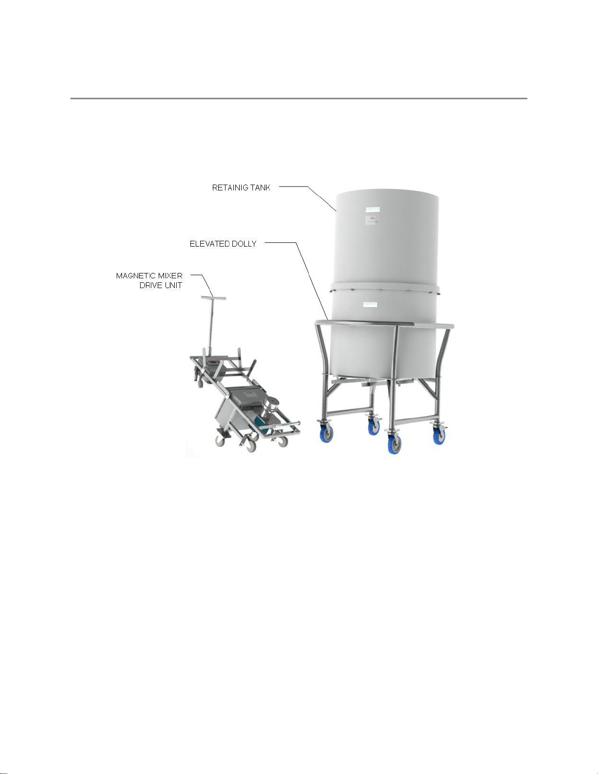
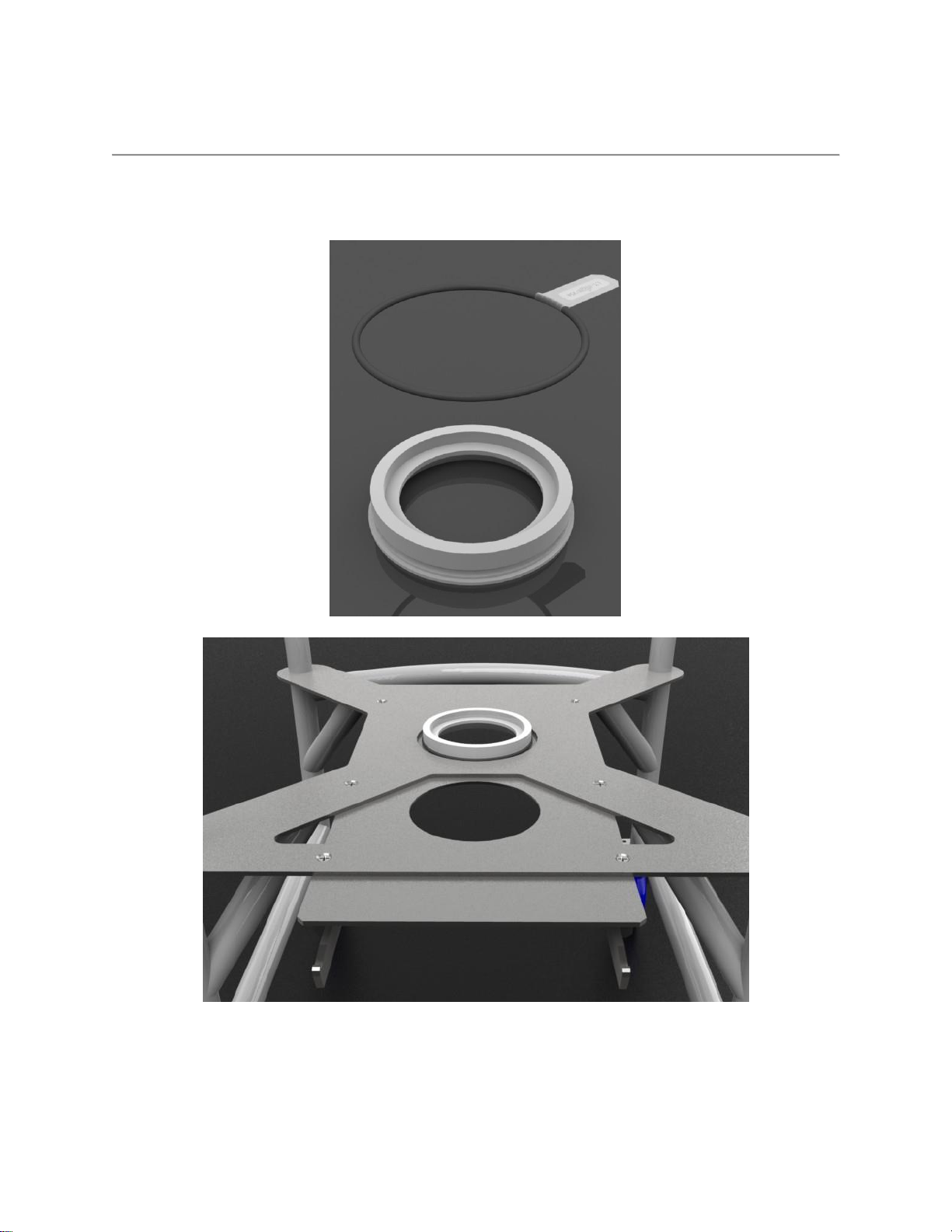
The Magnetic Mixer disposable bag mixing system is based on a single-use mixing bag
containing a bottom mounted disposable magnetic impeller on a disposable bearing. The single-
use magnetic impeller includes a proprietary bearing assembly designed and composed to
control particulate generation. All the materials of the impeller/bearing assembly contacting the
fluid are non-metallic USP Class VI and ADCF. The Magnetic Mixer disposable mixing system
consists of an interchangeable magnetic drive unit and proprietary magnetic impeller based
mixing bags fitted into retaining tanks on either a universal portable dolly (30L –500L) or a floor
mounted tank support (500L –2,000L). The magnetic Drive Motor is coupled with the mixing
bag through a proprietary interface. The activation of the motor induces rotation of the in-bag
impeller (0-300 RPM) resulting in the mixing action inside a hermetically sealed bag. The
coupling of the in-bag impeller with the Drive Motor is accomplished by magnetic forces only,
therefore no dynamic seals or shaft penetration inside the bag is required. The Drive Motor is
mounted on a portable cart that can be easily disconnected from the bag and reconnected to
another mixing bag thereby allowing mixing in multiple bags of various sizes with a single Drive
Motor.
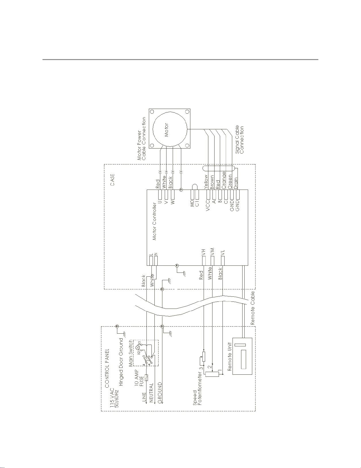
The system hardware has 4 major components:
1. Drive motor with control box and rotational speed display
2. Stainless Steel Dolly/platform for supporting the tank and interfacing with the drive
3. Plastic/Steel retaining tank for use on a dolly/stand
4. Accessory kit for interfacing the drive with the tank and bag
The Magnetic Mixer reusable system can accommodate a variety of standard and custom-
designed disposable bags and tanks available from Pall®Lifesciences with a capacity range
from 30L to 2000L.

Document #: 4100022 Revision: F Page #: 6 of 21
4. ELECTRICAL SCHEMATIC
115 VAC:

Document #: 4100022 Revision: F Page #: 7 of 21
230 VAC:

Document #: 4100022 Revision: F Page #: 8 of 21
MAGNETIC MIXER SYSTEM COMPONENTS
Figure 1: Main components of the Magnetic Mixer disposable mixing system (shown with 500L tank).

Document #: 4100022 Revision: F Page #: 9 of 21
5. MAGNETIC MIXER SYSTEM ACCESSORIES
6.1 Interface with O-ring: The Interface provides mechanical interfacing of the drive unit with
the impeller inside the bag.
Figure 2: Top: Drive-bag interface and O-ring.
Bottom: Interface is installed in the railed port of the dolly (locked by the O-ring).

Document #: 4100022 Revision: F Page #: 10 of 21
6.2 Centering Aligner and Magnetic Clamp: The Centering Aligner maintains centered
position of the impeller with respect to the interface. The Magnetic clamp provides holding
function for the bag in the tank before the fluid is put inside the bag. After the fluid is filled
to at least a level of 3”, the magnetic clamp can be removed as the hydrostatic pressure
from fluid will hold the bag in place.
Figure 3: Magnetic clamp (left) and Centering Aligner (right)
Figure 4: Assembly Magnetic clamp is assembled with the centering aligner prior to attachment to the bag

Document #: 4100022 Revision: F Page #: 11 of 21
6. DOLLY - TANK ASSEMBLY
Note: Certain larger tanks (>350L) are constructed in two parts.
7.1. The Dolly has a pre-cut hole over the drive port. Insert the Interface into this hole
from below and apply the O-ring as shown (see Figure 2)to secure. It is not
necessary to remove or replace the Interface after mixing or between batches.
7.2 Position the plastic tank on the dolly. The bottom surface of the tank has two pre-
cut holes: a small hole for the bag drain and a larger hole for the drive head. Line
up the larger hole with the hole in the dolly over the drive port. The larger whole
should fit loosely around the Interface.

Document #: 4100022 Revision: F Page #: 12 of 21
7. BAG - INTERFACE ASSEMBLY
Figure 5: Assembly of dry bag with interface
8.1 Carefully open the EXTERNAL packaging of the mixing bag. A blue protective shell is
magnetically attached to the outside of the bag over the locator. This shell must be
removed from the bag before assembling the interface.
8.2 Assemble the centering aligner and magnetic clamp as shown in Figure 5.

Document #: 4100022 Revision: F Page #: 13 of 21
8. INSERTING PLASTIC BAG INTO TANK
Figure 6: Bag-Tank Assembly
9.1 Place the bag in the plastic tank by aligning magnetic clamp with the large pre-cut port
on the bottom surface of the tank and pull the bottom drain tube through the smaller
port.
9.2 Insert the magnetic clamp in the appropriate pre-cut port.
9.3 Before filling the bag, ensure that all tubes are clamped, with the exception of the filling
tube. Ensure that the bottom drain tube is clamped.
9.4 As bag starts to fill, gently pull the bottom surface of the bag to remove any wrinkles,
especially near the impeller.
DO NOT exceed recommended bag capacity
DO NOT alter the tube and/or impeller configuration of bags

Document #: 4100022 Revision: F Page #: 14 of 21
9.COUPLING THE BAG WITH THE DRIVE UNIT
Figure 7: Coupling of magnetic mixer drive with the bag can be accomplished only when the bag is filled with fluid
(No coupling should be attempted with an empty or dry bag! The impeller will damage the bag.)
10.1 Remove Magnetic Clamp from the bag-tank assembly before coupling. To remove the
magnetic clamp, reach underneath the drive port and carefully pull the magnetic clamp
until it is free from the bag-tank assembly. Return the magnetic clamp to the supplied
Accessories Box for future use.
10.2 Shift the latch toward the control box slightly, (as shown in the first segment of Figure 7).
10.3 Carefully press down on the drive handle and raise the front wheels off the ground (as
shown on the second segment of Figure 7)
10.4 Align the guide bearings with the guide rails on the drive port.
10.5 Roll the drive unit along the rails all the way until the bearings are caught in the well
located at the dead end of the rails.

Document #: 4100022 Revision: F Page #: 15 of 21
10.6 Using the drive unit handle, raise the superconductive drive unit to an upright position.
While holding the drive unit in this position shift the latch toward the dolly/tank so that the
cross bar rests on the grooves in the guide rails (as shown in the forth segment of
Figure 7).
DO NOT put fingers under Locking Lever when locking the Drive Unit onto the Dolly
DO NOT attempt to move the Dolly with the Drive Unit Handle while the system is
assembled (doing so might damage the drive unit). Always use the dolly push handle to
move the Dolly or Dolly/Drive Unit assembly.
10. DRIVE MOTOR OPERATION
11.1 Plug the power cord in to the proper power source identified on the nameplate of the
system.
11.2 Place the knob of the speed control potentiometer in ZERO position by turning it all the
way counterclockwise.
11.3 Depress the round button of the main switch to energize the system (the button will
illuminate).
11.4 Press the RUN (green) button on the speed readout.
11.5 Set the speed of the mixer by turning the potentiometer clockwise until the desired
speed value illuminates on display.
11.6 To stop the motor press the STOP (red) button on the speed readout. Press the RUN
(green) button to resume motor operation at a preset speed. See Figure 8 (below) for
details on the control Box.
Figure 8: Control Box

Document #: 4100022 Revision: F Page #: 16 of 21
11. DISCONNECTING DRIVE UNIT FROM TANK
12.1 When mixing is complete, turn the RPM Regulator to zero (0) and turn the drive
switch to the STOP position. (Ensure that electrical power remains connected to the
machine when mixing multiple bags consecutively.)
12.2 Firmly hold the drive unit handle and raise the drive unit slightly to release the locking
lever. Release the locking lever by pulling it toward the control box.
12.3 Carefully lower the rear wheels of the drive unit to the floor and roll the drive unit on
its rear wheels away from the dolly.
12.4 Press down on the drive unit handle just until the guide bearings are free from the
guide rails.
12.5 Pull the drive unit slightly farther away from the dolly and carefully lower the front
wheel to the ground.
12.6 The tank can now be wheeled to another station on the elevated dolly. The
Superconducting Drive Unit remains ready for mixing.
12.7 To drain fluid from the bag, unclamp the bottom drain tube.
12.8 When the bag is completely drained, remove the bag by carefully pulling the impeller
seat and the drain tube out of their respective ports.
12.9 Remove the centering aligner from the tank and return to the supplied Accessories
Box for future use. The Interface should remain in its locked position for future use.
12.10 Always put the protective shell back on the bag before disposal.
12.11 Dispose of plastic bag.

Document #: 4100022 Revision: F Page #: 17 of 21
12. EZD OPERATING INSTRUCTIONS
WARNING: EZD Clip (4100153) must be installed on the bag before
operating EZD valve or bag can be damaged
EZD stands for Easy Drain meaning a drain that allows easy transfer of fluid to and from the
container. The typical applications include draining a container or filling a container with liquid.
EZD operation involves relative movement of EZD Male port with respect to EZD Universal
Fitment. The Universal Female fitment always remains stationary and it is only the relative
vertical movement of EZD Male port that allows fluid transfer through the port. The EZD is
closed to fluid transfer when the top surface of the EZD male port is flush with the top surface of
EZD universal fitment. When the EZD male port is pushed into the EZD universal fitment, it is
open for fluid transfer. The Collar is used to lock the EZD valve in the preferred position (either
open or closed) by rolling it over the fingers of the EZD universal fitment. When the collar is over
the EZD universal fitment fingers, it prevents movement of the EZD valve and when it is rolled
away from the finger region of the universal fitment, it allows the EZD valve to move from a
closed to open or open to closed position.
A necessary step to use EZD is that, an EZD CLIP be installed on the EZD universal
fitment prior to start using it. The EZD CLIP should be mounted on universal fitment as
shown in the image below.

Document #: 4100022 Revision: F Page #: 18 of 21

Document #: 4100022 Revision: F Page #: 19 of 21
13. Pall®LifeSciences - SERVICE
The Magnetic Mixer system was developed exclusively for mixing fluids and solids into fluids in
specially designed disposable bags. Only use the Magnetic Mixer for these applications to
ensure a long service life.
Should your Magnetic Mixer require service, contact:
North America:
PALL Life Sciences
20 Walkup Drive
Westborough, MA 01581
Europe:
PALL Life Sciences
Reugelstraat 2, B-3320 Hoegaarden, Belgium
Phone: +32 (0) 16.76.61.59
Fax: +32 (0) 16.76.76.25
Magnetic Mixer
Patents:
Pall.com/patents
14. SPARE PARTS
MM-DBBI002 Centering Aligner
MM-DBBI007 Magnetic Clamp
MM-DBBI008 Drive-Bag Interface
MM-DBBI004 O-Ring for use with Drive-Bag Interface
MM-LTOE059 M1 Latch Assembly
MM-LTOE060 M2 Latch Assembly
MM-LTOE061 Magnetic Mixer Rollers
2100024 Fuse

This manual suits for next models
5
Table of contents
Other Pall Mixer manuals
Popular Mixer manuals by other brands

Cuisinart
Cuisinart Precision Master SM-35 Series INSTRUCTION AND RECIPE BOOKLET

Sage
Sage the Scraper Mixer Pro BEM800UK Instruction book

Klarstein
Klarstein 10028901 manual

Cuisinart
Cuisinart SM-55 - Stand Mixer Recipes

Scheppach
Scheppach MIX160 Translation of original instruction manual

Scheppach
Scheppach MIX160 Translation from the original instruction manual

Sunbeam
Sunbeam Mixmaster MX001 Instruction/recipe booklet

Keysight Technologies
Keysight Technologies X Series user guide

VARO
VARO POWERPLUS POWDP7080 manual

Hamilton Beach
Hamilton Beach 63326 use & care

Mistral
Mistral MFM495 instruction manual

Pentair
Pentair HBM 200 series Installation and service manual