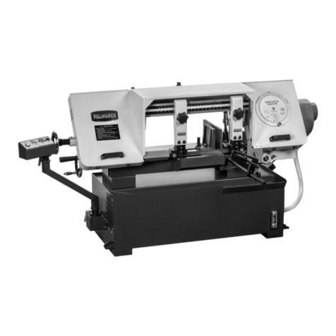
Palmgren 9683314 User manual

oper ting m nu l & p rts list 9683314
9 X 16″METAL CUTTING BAND SAW
Read carefully and follow all safety rules and operating instructions before
first use of this product.
9641488.01-1216

DESCRIPTION
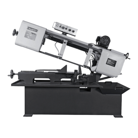
9 x 16” Horizontal Metal Cutting Band Saw provides speed with
quality of cut for fabrication shops, machine shops, mainte nance
departments and contractors. Blade speed ranges from 82 to 235
FPM to cut a variety of material ranging from cast iron, tool steel,
bronze, aluminum and plastic.
The feed rate is regulated by a hydraulic cylinder. The dial control for
the cylinder is accessible during all stages of proper operation and
can be set at any feed rate within its range. The wet cut operation
provides a quality cut and extends blade life. Features include auto -
matic shutoff, industrial rated speed reducer, heavy gauge steel
construction, cast iron wheels, pulleys and bed.
Additional features include swivel vise jaws for angle cuts, built in
chip tray and flange mounting brackets for securing saw to floor.
Saw is controlled by push button magnetic switch with safety off
button.
UNPACKING
Check for shipping damage. If damage has occurred, a claim must be
filed with carrier immediately. Check for completeness. Immediately
report missing parts to dealer.
The band saw comes completely assembled as one unit. Additional
parts which need to be fastened to the saw should be located and
accounted for before assembling:
V-Belt Motor assembly, pulley cover, electrical control box and work
stop assembly.
NOTE: Work stop assembly is located in coolant reservoir under chip
tray.
WARNING: Be careful not to touch overhead power lines, piping,
lighting, etc. if lifting equipment is used. Band saw weighs
approximately 625 lbs. Proper tools, equipment and qualified
personnel should be employed in all phases of unpacking and
installation.
IM ORTANT: Bed is coated with a protectant. To ensure proper fit
and operation, remove coating. Coating is easily removed with mild
solvents, such as mineral spirits, and a soft cloth. Avoid getting clean -
ing solution on paint or any of the rubber or plastic parts. Solvents
may deteriorate these finishes. Use soap and water on paint, plastic
or rubber components. After cleaning, cover all exposed surfaces
with a light coating of oil. Paste wax is recommended for bed top.
WARNING: Never use highly volatile solvents. Non-flammable
solvents are recommended to avoid possible fire hazard.
SPECIFICATIONS
Capacity . . . . . . . . . . . . . . . . . . . . . . . . . . . . . . . . . . . . . . . . . 9” Rounds at 90°
6
1
⁄2” Rounds at 45°
2 x 16” Rectangle at 90°
9 x 14” Rectangle at 90°
9 x 6
1
⁄2” Rectangle at 45°
Motor . . . . . . . . . . . . . . . . . 1
1
⁄2HP, 1720 RPM, 120/240 Volts, 16/8 Amps
Blade speeds . . . . . . . . . . . . . . . . . . . . . . . . . . . . 82, 132, 170 and 235 FPM
Blade size . . . . . . . . . . . . . . . . . . . . . . . . . . . . . . . . . . . . . . . . 1 x .035 x 119
1
⁄2”
Blade wheels . . . . . . . . . . . . . . . . . . . . . . . . . . . . . . . 13” Diameter cast iron
Overall dimensions . . . . . . . . . . . . . . . . . . . . . . . . . . . . . . . . . 67 x 23 x 43
1
⁄2”
Weight . . . . . . . . . . . . . . . . . . . . . . . . . . . . . . . . . . . . . . . . . . . . . . . . . . . . 625 lbs
Coolant pump . . . . . . . . . . . . . . . . . . . . . . . . . . . . 2.25 allons per minute
Coolant reservoir capacity . . . . . . . . . . . . . . . . . . . . . . . . . . . . . . 4.4 allons
GENERAL SAFETY INFORMATION
WARNING: For your own safety, read all of the instructions and
precautions before operating tool.
RO OSITION 65 WARNING: Some dust created by using power
tools contain chemicals known to the state of California to cause
cancer, birth defects or other reproductive harm.
Some examples of these chemicals are:
• Lead from lead-based paints.
• Crystalline silica from bricks and cement and other masonry
products.
• Arsenic and chromium from chemically treated lumber.
WARNING: Your risk from these exposures vary, depending on how
often you do this type of work. To reduce your exposure to these
chemicals: work in a well ventilated area and work with approved
safety equipment. Always wear OSHA/NIOSH approved, properly
fitting face mask or respirator when using such tools.
CAUTION: Always follow proper operating procedures as defined
in this manual — even if you are familiar with use of this or similar
tools. Remember that being careless for even a fraction of a second
can result in severe personal injury.
BE RE ARED FOR JOB
• Wear proper apparel. Do not wear loose clothing, gloves,
neckties, rings, bracelets or other jewelry which may get caught
in moving parts of machine.
• Wear protective hair covering to contain long hair.
• Wear safety shoes with non-slip soles.
• Wear safety glasses complying with United States ANSI Z87.1.
Everyday glasses have only impact resistant lenses. They are
NOT safety glasses.
• Wear face mask or dust mask if operation is dusty.
• Be alert and think clearly. Never operate power tools when tired,
intoxicated or when taking medications that cause drowsiness.
RE ARE WORK AREA FOR JOB
• Keep work area clean. Cluttered work areas invite accidents.
• Do not use power tools in dangerous environments. Do not use
power tools in damp or wet locations. Do not expose power tools
to rain.
• Work area should be properly lighted.
• Proper electrical receptacle should be available for tool. Plug
120/240 volt, single-phase plug directly into properly grounded,
three-prong receptacle.
• Extension cords should have a grounding prong and the three
wires of the extension cord should be of the correct gauge.
• Keep visitors at a safe distance from work area.
• Keep children out of workplace. Make workshop childproof. Use
padlocks or master switches to prevent any unintentional use of
power tools.
2
Palmgren Operating Manual & Parts List 9683314
3
SAFETY INFORMATION (CONTINUED)
TOOL SHOULD BE MAINTAINED
• Always unplug tool prior to inspection.
• Consult manual for specific maintaining and adjusting
procedures.
• Keep tool lubricated and clean for safest operation.
• Remove adjusting tools. Form habit of checking to see that
adjusting tools are removed before switching machine on.
• Keep all parts in working order. Check to determine that the
guard or other parts will operate properly and perform their
intended function.
• Check for damaged parts. Check for alignment of moving parts,
binding, breakage, mounting and any other condition that may
affect a tool’s operation.
• A guard or other part that is damaged should be properly
repaired or replaced. Do not perform makeshift repairs. (Use parts
list provided to order repair parts.)
KNOW HOW TO USE TOOL
• Use right tool for job. Do not force tool or attachment to do a job
for which it was not designed.
• Disconnect tool when changing blade.
• Avoid accidental start-up. Make sure that the tool is in the OFF
position before plugging in.
• Do not force tool. It will work most efficiently at the rate for which
it was designed.
• Keep hands away from moving parts and cutting surfaces.
• Never leave tool running unattended. Turn the power off and do
not leave tool until it comes to a complete stop.
• Do not overreach. Keep proper footing and balance.
• Never stand on tool. Serious injury could occur if tool is tipped or
if blade is unintentionally contacted.
• Know your tool. Learn the tool’s operation, application and
specific limitations.
• Use recommended accessories (Refer to page 23). Use of
improper accessories may cause risk of injury to persons.
• Handle workpiece correctly. Protect hands from possible injury.
• Turn machine off if it jams. Blade jams when it digs too deeply
into workpiece. (Motor force keeps it stuck in the work.) Do not
remove jammed or cut off pieces until the saw is turned off,
unplugged and the blade has stopped.
CAUTION: Think safety! Safety is a combination of operator
common sense and alertness at all times when tool is being used.
ASSEMBLY
MOUNT CONTROL BOX ASSEMBLY
Refer to Figures 17 and 20.
• Remove hex head bolts, lock washers and flat washers (Figure 20,
Ref. Nos. 30, 31, and 32) from column (Figure 17, Ref. No. 1).
• Secure control box (Figure 20, Ref. No. 33) to column using hex
head bolts, lock washers and flat washers.
INSTALL MOTOR ASSEMBLY
Refer to Figure 17.
• Remove socket head bolt, lock washer and flat washer (Ref. Nos.
45, 34 and 33) from side of motor mount plate (Ref. No. 42).
• Remove hex nut and flat washer (Ref. Nos. 47 and 46) from
support shaft (Ref. No. 50). Remove support shaft from motor
mount bracket (Ref. No. 48).
• Slide support shaft through motor mount bracket and motor tilt
plate. (Ref. No. 44) Secure support shaft with hex nut and flat
washer.
• Slide socket head bolt with lock washer and flat washer through
slot in motor tilt plate (Ref. No. 44) and thread into motor mount
plate. Do not tighten socket head bolt until V-belt is installed and
adjusted.
MOUNT ULLEY COVER
Refer to Figure 17.
• Remove knob (Ref. No. 30) from pulley cover (Ref. No. 31).
• Remove socket head bolts, lock washers and flat washers (Ref.
Nos. 35, 34 and 33) from drive wheel housing and motor mount
bracket (Ref. Nos. 20 and 48).
• Secure pulley cover using socket head bolts, lock washers and
flat washers.
INSTALL V-BELT
Refer to Figures 12 and 17.
• Band saw uses a step-pulley drive system to provide a selection
of blade speeds.
• Place V-belt (Ref. No. 36) on drive and motor pulleys (Ref. Nos. 32
and 37) with V-belt in desired location on pulleys. See Figure 12,
Blade Speed Chart.
• Do not over tighten V-belt. Excessive tension on V-belt will
reduce life of belt. Belt is properly tensioned when light pressure
applied between pulleys produces about 1/2” deflection.
• Tension V-belt by pushing motor mount plate and tightening
socket head bolt (Ref. Nos. 42 and 45).
• Close pulley cover and secure with knob (Ref. Nos. 31 and 30).
WIRE MOTOR
• Remove pan head screw and cover from motor junction box.
• Pass motor cord through strain relief and secure cord with screw
on strain relief.
• Wire motor line cord to motor with screws provided. Be sure to
ground motor with green grounding wire in motor cord.
• Replace junction box cover and secure with pan head screw.
ATTACH WORK STO ASSEMBLY
Refer to Figure 15.
• Thread work stop rod (Ref. No. 13) into bed (Ref. No. 18).
• Slide work stop assembly (Ref. Nos. 15, 16 and 17) onto work stop
rod and secure with knob (Ref. No. 14).
• Adjust the work stop as described in Operation, page 11.
Palmgren Operating Manual & Parts List 9683314
INSTALLATION
Refer to Figures 1 – 7.
CAUTION: Do not attempt installation if parts are missing. Use this
manual to order repair parts.
Before band saw is installed, a suitable location should be chosen.
Band saw weighs approximately 625 lbs.
• Band saw needs to be set on a flat, level surface.
• Make sure there is ample room for the workpiece.
• ood lighting and correct power supply are also required for a
proper work area.
OWER SOURCE
Band saw comes prewired for 120 volt, 60 Hz power. To prolong
electrical component life, it is recommended to rewire it to 240 volt,
single phase operation.
WARNING: All electrical connections must be performed by a
qualified electrician. Make sure tool is off and disconnected from
power source while motor is mounted, connected, reconnected or
anytime wiring is inspected.
To rewire band saw to 240 volt, single phase operation:
• Rewire main motor to 240V. Refer to Figure 3 and motor
nameplate for wiring schematic.
• Rewire coolant pump to 240V. Refer to Figure 4 and wiring
schematic found on the inside of motor’s junction box cover.
• Change the wire position from the 115V or 230V, to the desired
voltage setting, See Figure 4.
• Change thermal overload setting to 14A for 240V operation. For
120V operation, thermal overload should be set to 17A as shown
in Figure 5.
NOTE: The thermal overload will automatically turn off the magnetic
contactor when an overload occurs. Be sure to disconnect band saw
from power source when resetting overload protector. The
protection is reset by pressing the rest button.
4
Palmgren Operating Manual & Parts List 9683314
Figure 2 - Electrical anel Layout
Figure 1 - Electrical Schematic for 1 hase 240V
Figure 3 – Main Motor Wiring Diagram
3-Red 2- ray
4-Yellow
1-Black
120V
240V
3-Red
1-Black
2- ray
4-Yellow
Figure 4 – Coolant ump Motor Wiring Diagram
3-Black 2-Black
4-Red
1-Red
120V
240V
3-Black
1-Red
2-Black
4-Red
Figure 5 – Setting Thermal Overload

5
Palmgren Operating Manual & Parts List 9683314
INSTALLATION (CONTINUED)
WARNING: Do not connect band saw to the power source until all
assembly steps have been completed.
The motor is designed for operation on the voltage and frequency
specified. Normal loads will be handled safely on voltages not more
than 10% above or below the specified voltage.
Running the unit on voltages which are not within the range may
cause overheating and motor burn-out. Heavy loads require that the
voltage at motor terminals be no less than the voltage specified.
GROUNDING INSTRUCTIONS
WARNING: Improper connection of equipment grounding
conductor can result in the risk of electrical shock. Equipment should
be grounded while in use to protect operator from electrical shock.
Check with a qualified electrician if you do not understand
grounding instructions or if in doubt as to whether the tool is
properly grounded.
This tool is equipped with an approved cord rated at 250V and a
3-prong grounding type plug rated at 125V (See Figure 6) for your
protection against shock hazards.
rounding plug should be plugged directly into a properly installed
and grounded 3- prong grounding-type receptacle, as shown in
Figure 6.
Do not remove or alter grounding prong in any manner. In the event
of a malfunction or breakdown, grounding provides a path of least
resistance for electrical shock.
WARNING: Do not permit fingers to touch the terminals of plug
when installing or removing from outlet.
Plug must be plugged into matching outlet that is properly installed
and grounded in accordance with all local codes and ordinances. Do
not modify plug provided. If it will not fit in outlet, have proper outlet
installed by a qualified electrician.
Inspect tool cords periodically, and if damaged, have repaired by an
authorized service facility.
reen (or green and yellow) conductor in cord is the grounding wire.
If repair or replacement of the electric cord or plug is necessary, do
not connect the green (or green and yellow) wire to a live terminal.
Where a 2-prong wall receptacle is encountered, it must be replaced
with a properly grounded 3-prong receptacle installed in accordance
with National Electric Code and local codes and ordinances.
WARNING: This work should be performed by a qualified
electrician.
A temporary 3-prong to 2-prong grounding adapter (See Figure 7) is
available for connecting plugs to a two pole outlet if it is properly
grounded.
NOTE: A temporary 3-prong to 2-prong grounding adapter is
available only for 115 volt operation.
Do not use a 3-prong to 2-prong grounding adapter unless
permitted by local and national codes and ordinances.
(A 3-prong to 2-prong grounding adapter is not permitted in
Canada.) Where permitted, the rigid green tab or terminal on the
side of the adapter must be securely connected to a permanent
electrical ground such as a properly grounded water pipe, a properly
grounded outlet box or a properly grounded wire system.
Many cover plate screws, water pipes and outlet boxes are not
properly grounded. To ensure proper ground, grounding means
must be tested by a qualified electrician.
EXTENSION CORDS
• The use of any extension cord will cause some drop in voltage
and loss of power.
• Wires of the extension cord must be of sufficient size to carry the
current and maintain adequate voltage.
• Use the table to determine the minimum wire size (A.W. .)
extension cord.
• Use only 3-wire extension cords having 3-prong grounding type
plugs and 3-pole receptacles which accept the tool plug.
• If the extension cord is worn, cut, or damaged in any way, replace
it immediately.
EXTENSION CORD LEN TH
Wire Size A.W. .
Up to 25 ft. . . . . . . . . . . . . . . . . . . . . . . . . . . . . . . . . . . . . . . . . . . . . . . . . . . . . .14
NOTE: Using extension cords over 25 ft. long is not recommended.
OPERATION
Refer to Figures 8-20.
The 9 x 16”, 4-speed horizontal band saw blade speeds range from 82
to 235 FPM.
Vise jaws can turn 0-45° for making angle cuts. Movable jaw has
rapid approach and withdraw capability.
WARNING: Always observe the following safety precautions.
• Whenever adjusting or replacing any parts on the band saw turn
switch off and remove plug from power source.
• Make sure the stops are positioned and that the automatic shut-
off is operating.
• Check that the gear box has the proper amount of lubricant.
• Make sure the blade guides are positioned correctly.
• Use the appropriate blade for the workpiece that is being cut.
• Use a sharp blade. Replace dull blades or blades which are
missing teeth.
• Make sure the blade is tensioned properly and going in the right
direction.
• Use the proper blade speed for the work.
• For optimum performance, do not stall the motor or reduce the
speed. Use the proper feed pressure.
• Make sure enough coolant is available to keep coolant pump
(Figure 12, Ref. No. 10) submersed.
• Secure the workpiece in a stable position.
• Check that all guards are attached.
Figure 7 – 2- rong Receptacle with Adapter
rounding Lug
Adapter
3-Prong Plug
2-Prong Receptacle
Make sure this is
connected to a known
grounded receptacle.
Figure 6 – 3- rong Receptacle
Properly rounded Outlet
rounding Prong
3-Prong Plug

6
Palmgren Operating Manual & Parts List 9683314
OPERATION (CONTINUED)
• After turning the switch on, let the blade come to full speed.
Then lower the blade onto the workpiece slowly.
• Keep hands away from the blade and all moving parts.
• Always wear eye protection.
O ERATING SAW CONTROLS
Refer to Figure 8.
Band saw control panel has seven functional operations:
POWER - reen color lamp that is illuminated when saw is plugged
in.
KEY LOCK - Safety mechanism to prevent unauthorized use. Turn the
key to ON position to energize the saw circuitry. Turn the key to OFF
position and remove key when tool is not in use.
NOTE: The motor will not start if the key is in the OFF position.
ON - reen color push button that energizes the magnetic contactor
to start the band saw.
OFF - Red color push button that deenergizes the magnetic
contactor to stop the band saw. To restart the saw, turn the knob to
reset and depress the ON button.
PUMP switch - Two position ON/OFF switch to operate the coolant
pump.
FEED RE ULATOR - Dial knob to set band saw feed rate. Set the feed
rate suitable to application.
FEED CONTROL - Two position ON/OFF knob engages and
disengages feed.
HORIZONTAL STO
Refer to Figure 17.
Horizontal stop (Ref. No. 14) controls the position of the head at the
end of the cut. Bed should contact the horizontal stop when teeth
are 1/8” below the surface of the workbed.
HORIZONTAL STO ADJUSTMENT
Refer to Figure 17.
• Place head in the horizontal position.
• Loosen the nut (Ref. No. 9) on the horizontal stop.
• Adjust the horizontal stop so that the teeth are 1/8” below the
surface of the workbed.
• Tighten the nut to lock the position.
AUTOMATIC SHUTOFF
Refer to Figure 15.
The limit switch (Ref. No. 44) is activated when the blade passes
through the plane of the workbed. The limit switch should be
activated as soon as the cut is finished.
IM ORTANT: Make sure the action of the limit switch is not
restricted by the horizontal stop.
LUBRICATION
• All ball bearings are permanently lubricated. They should not
require further lubrication.
• If the tracking wheel or head pivot is disassembled for any
reason, wipe off the old grease before assembly.
OIL LEVEL
Refer to Figure 19.
• The gear box relies on an oil bath to lubricate the sliding surfaces
and transfer heat. The vent bolt (Ref. No. 8) is vented to release
pressure created by the developed heat. Insufficient lubrication
will cause the gears to heat up and wear at an accelerated rate. If
the gear box is overfilled, hot oil will escape through the vent
hole. The gear box is designed to take 51 ounces of 70-95 weight
industrial gear oil.
• The oil level should remain constant. If the level changes, a
defective gasket or bushing should be looked for and replaced.
• If the gear box is worked on, the oil should be replaced to avoid
contamination.
• Always add fresh oil and replace the oil seasonally, to guard
against breakdown.
• The seals between the gearbox and the cover plates are gaskets
(Ref. Nos. 14 and 24). If a cover plate is removed, the surface
should be cleaned and new gasket should be applied.
• After the first fifty hours of use, the gear box should be drained
and refilled with industrial gear oil (Model No. 6Y785).
CHECKING OIL LEVEL
Refer to Figures 9 and 19.
• Place the head in the horizontal position.
• Let the oil settle. Allow a few minutes if the head was in motion.
• Check the fluid level. Look at the oil sight lens (Ref. No. 19) and
follow the instructions in Figure 9.
Figure 8 – Band Saw Control anel
Power
Pump Switch
Feed Regulator
Feed Control
Key Lock
ON
OFF
Figure 9 – Checking Oil
Sight lens full of oil: Drain oil by
removing drain plug (Ref. No. 18)
Sight lens half-covered: The oil
level is correct
No oil visible: Remove vent bolt
(Ref. No. 8) and add oil

7
Palmgren Operating Manual & Parts List 9683314
OPERATION (CONTINUED)
BLADE GUIDES
Band saw blade has to be twisted relative to the plane in which it
rotates. Blade must be properly positioned relative to the workbed.
Blade guides hold the cutting portion of the blade in a plane which
is perpendicular to both the workbed and the stationary vise and
keeps the blade in line with its natural path around the blade
wheels.
Inner guide bearings on the left and right guide assemblies keep the
blade in line with the blade wheels. Outer guide bearings keep the
blade against the inner bearings.
Entire guide assembly is positioned at the factory to produce the
proper twist and should not need adjustment, however, the position
of blade guides should be checked often.
NOTE: Since the blade position is related to both bed and the vise
jaws, the relative position of the jaw to the bed is important. When
assembled, the stationary jaw must be perpendicular to the surface
of the workbed.
CHECKING BLADE GUIDES
Refer to Figure 18.
• Check that the blade teeth are perpendicular to the base’s
machined surface.
• Spread the blade guides as far apart as possible.
• Check that vise jaws are parallel and set for 90° cutoff.
• Position the vise jaws to have the maximum separation that will
not interfere with the blade guides.
• With the head in horizontal position, use a square against face of
rear vise jaw and check that jaw is 90° to the side of blade.
• Check that the blade is in line with drive and tracking wheels
(Ref. Nos. 3 and 30).
• Raise the head.
• Look straight on at the cutting edge of the blade.
• Make sure that the blade sides are parallel to the sides of the
bearings.
• Make sure the bearings (Ref. No. 9) touch the blades and can still
be rotated by hand.
ADJUSTING GUIDE BEARINGS
Refer to Figure 18.
If the blade is not perpendicular to the bed or not in line with the
blade wheels, adjustment is necessary.
NOTE: There should be .000-.001” clearance between the blade and
the guide bearings.
The guide bearings are adjusted using an eccentric location system.
The inner guide bearings are fixed and cannot be adjusted. The outer
guide bearings are mounted to eccentric sleeves (Ref. No. 10) and
can be adjusted.
• Loosen socket head bolt (Ref. No. 6) with a wrench. Rotate the
eccentric shaft to locate bearings in desired positions.
• Maintain eccentric shaft position and tighten socket head bolt.
CHECKING THRUST BEARINGS
Refer to Figure 18.
The thrust bearings (Ref. No. 20) should be .003-.005” (average
thickness of a piece of paper) away from back of blade.
The thrust bearings are adjusted by moving the guide bracket.
ADJUSTING GUIDE BRACKETS
Refer to Figure 18.
• If the bearings are positioned properly and the blade is not
square, one or both blade guide brackets (Ref. Nos. 21 and 56)
must be adjusted.
• Loosen the socket head bolts (Ref. No. 23 and 58).
• Adjust the bracket to the correct position.
• Tighten the socket head bolt.
• Check the guide bearings. Repositioning the blade guide bracket
can alter the previous adjustments. Readjust if necessary.
BLADE SELECTION
Using the proper blade is important for setting up the correct
cutting conditions. Blades are made differently depending on the
specific application intended for the blade. Some simple rules can
still be applied to almost all blades.
• Always remember to have at least three teeth in contact with the
work during a cut. When three teeth are in contact, the blade
cannot straddle the work. This prevents a tooth that enters the
cut from encountering more material than it can remove.
• “Shocking” occurs when blade teeth contact too much material.
This can strip the teeth from the blade. When cutting harder
materials, the suggested minimum number of teeth in contact is
six because “shocking” on harder materials has a more
detrimental effect on the blade. Optimum number of teeth in
contact with workpiece distributes blade forces among more
teeth to increase cutting efficiency and reduces blade wear.
• Optimum range is from 6-12 teeth in contact for soft materials,
up to 12-24 teeth in contact for harder materials.
• Always have maximum number of teeth in contact with work to
prevent gullets of teeth from being clogged.
• When choosing a blade, overall size of the work is not as
important as the thickness average. Thickness average is the
average width of material which blade will contact during each
cut. Figure 10 describes how thickness average should be
calculated.
• Thickness average should be used when choosing a blade for the
optimum number of teeth in contact, however, the three teeth
rule should be applied to the minimum thickness, not thickness
average.
• Keeping a selection of sharp blades on hand will yield better
cuts. Blades may last longer because they are less likely to be
misused when proper blade is available.
• Every band saw should have at least one replacement blade of
each type used. Blade breakage is unpredictable. Consult a blade
manufacturer for detailed information about available blades for
specific uses.
REMOVING BLADE
Refer to Figure 17.
WARNING: Disconnect band saw from power source when
changing or adjusting blades. Wear leather gloves when handling
band saw blades. Never wear gloves when operating saw.
• Prop open the blade wheel covers.
• Loosen the outer guide bearings on the left and right guide
assemblies. No other guide bearings should be moved.
• Remove knobs and blade guard (Ref. Nos. 17 and 18).
• With one hand, pinch the blade and the tracking wheel together
to protect against the possibility of the blade popping off when
tension is released.
• Release the tension by slowly revolving the hand wheel (Ref. No.
69) counterclockwise.
• Remove the blade.

8
Palmgren Operating Manual & Parts List 9683314
OPERATION (CONTINUED)
RE LACING THE BLADE
• Make sure the outer guide bearings are loose.
• Make sure the teeth are pointing in the right direction (See
Figure 10).
• Place the blade around the wheels and between the guide
bearings.
• Hold the blade in position and apply tension. Blade tension
generally must be set at 25000 psi for hard back blades, and
35000 psi for bi-metal blades. Use tension scale (Figure 17, Ref.
No. 56).
• Push the blade against the wheel flange.
• Tighten the blade until it is properly tensioned. A properly
tightened blade will ring slightly when the back of the blade is
plucked (like a string of an instrument).
• Adjust the outer guide bearings.
• Check for proper tracking (See Tracking Adjustment).
TRACKING
Proper tracking is achieved when the drive wheel and tracking
wheel are aligned. A blade that is not tracking correctly can come off
the blade wheels. Although adjustment is rarely required, tracking
should be checked frequently.
CAUTION: Turn motor off and disconnect power to check tracking.
CHECK TRACKING
• Prop open the blade wheel covers.
• Insert a piece of paper between the blade and the lower portion
of the tracking wheel.
• Open the pulley cover and rotate the blade by turning the motor
pulley.
• Let the blade grab the paper. Rotate the pulley so the paper goes
around the wheel.
• Refer to Figure 11 to determine if an adjustment is needed.
TRACKING ADJUSTMENT
Refer to Figures 10, 11 and 17.
The tracking is adjusted by positioning the idler wheel shaft (Ref. No.
61). The positioning is done with the hex head bolts (Ref. No. 58) only
if the upper socket head bolts (Ref. No. 60) are loose.
• Loosen the three socket head bolts.
• Adjust the tilt with hex head bolts. For correct tracking, refer to
Figure 11. Turn 1/4 revolution at a time.
• Check the blade tension and adjust if necessary.
• Recheck the tracking.
• Once the proper position has been found, tighten the bolts
securely.
BLADE S EED
Refer to Figures 12 and 17.
Choosing the proper blade speed is important for extending the life
of the blade. The speed determines the available cutting force.
• Harder materials require more force and are cut at a slower
speed.
• Softer materials are cut with less force at higher speeds to ensure
the proper removal of the chips.
• The speed and corresponding force are related to the power
supplied to the blade. Four speeds are available.
• If a motor, other than the one supplied is used, the cutting
conditions will be changed. Four speeds are available.
• Speed is changed by moving V-Belt (Ref. No. 36) to one of the
four pulley positions. Speeds and corresponding pulley
configurations are illustrated below.
F M
82 . . . . . . . . . . . . . . . . . . . . . . Stainless steel, bearing bronze, alloy steels.
132 . . . . . . . . . . . . . . . . . . . . . .Medium to high carbon steels, hard brass.
170 . . . . . . . . . . . . . . . .Low to medium carbon steels, soft brass, copper.
235 . . . . . . . . . . . . . . . . . . . . . . . .Aluminum, plastic, other light materials.
CHANGING BELT OSITION
Refer to Figure 17.
• Remove knob (Ref. No. 30) from pulley cover (Ref. No. 31)
• Open pulley cover. Loosen socket head bolt (Ref. No. 45).
• Move the belt to the desired position.
• Tighten the socket head bolt to tension the belt. Belt is tensioned
properly when a moderate pressure applied to the belt between
the pulleys produces a 1/2” of deflection.
• Secure pulley cover with knob.
Figure 10 – Blade Direction
Figure 11 – Tracking Adjustments
A sharp fold indicates
proper tracking.
Cut or ripped paper indicates
that the blade is riding against
the flange of the wheel.
Adjusting bolt needs to be
turned counterclockwise.
No fold indicates the blade
will ride off the wheel.
Adjusting bolt should be
turned clockwise.
Figure 12 – Speed and ulley Diagram
82
132
170
235

OPERATION (CONTINUED)
FEED RESSURE
• Correct feed pressure holds the blade in the cut. Feed pressure is
supplied by the weight of the head. Maximum material removal
rate corresponds with the proper pressure.
• Optimum feed pressure ensures that maximum power is used for
cutting. If the feed pressure is too low, the blade will not dig into
the material properly. Too much feed pressure will cause the
blade to dig too deeply, bogging down the motor, and possibly
burning it out. In addition, blade “shocking” could result.
• Extra energy will be used to produce powdered chips rather than
smooth shavings; this will produce more heat and dull the blade.
CAUTION: Do not attempt to increase feed pressure by leaning on
head.
REGULATING FEED RESSURE
Refer to Figures 8 and 13.
• Feed pressure is controlled by the feed regulator. The regulator
creates a force which counteracts the feed pressure. The force
from the feed regulator can be adjusted to create any feed
pressure up to the set maximum.
• Having the correct feed pressure will produce the optimum feed
rate and the fastest cut. Incorrect pressure, whether too great or
too small, will put less power into the cut and reduce the feed
rate.
NOTE: Wasted power damages the saw.
• Determining the proper feed is largely a judgement based on
experience. The feed is usually determined during the cutting
operation. Before the cutting begins, the blade should be off the
work and the head should be held in position by placing the feed
control knob (See Figure 8) in the OFF position
• Once the blade is running, the head is slowly lowered onto the
work by turning the feed control knob to the on position, and
adjusting the feed regulator knob to the desired feed rate.
• After the blade begins the cut, optimum feed rate should be
determined.
• To determine if the feed is incorrect, examine the chips
produced. When the blade is operating at the ideal feed for the
speed, the chips will be curled and continuous. If the chips are
thick and not continuous, the feed pressure should be reduced. If
the chips are powdery, the feed pressure needs to be increased
(Refer to Figure 13).
CUTTING FLUIDS
• Using a cutting fluid can improve the cutting conditions and
keep them more consistent throughout the cut by:
a. Lubricating the blade, which reduces the friction between it
and the workpiece.
b. Taking heat away from the cut and preventing the workpiece
and blade from overheating.
c. Dissipating the built-up heat because hot metals become
tough and more difficult to cut and blades become dull at an
accelerated rate.
NOTE: Because much of the built-up heat comes from friction
between the blade and the workpiece, cutting fluids are often
referred to as “coolants”.
• The importance of cutting fluids increases with blade speed and
toughness of the material.
• There are many available types of cutting fluids. Consult a
machinist’s handbook for specific information. The most
common general purpose coolant is a mixture of water and
water soluble oil (Model No. 6Y647). The producer of the water
soluble oil should provide the appropriate mixing ratios.
COOLANT TANK
Refer to Figure 16.
• The coolant reservoir (Ref. No. 14) can hold up to four and a half
gallons of coolant. For proper operation, the pump must be
completely submerged in fluid.
• Check that the fluid level is sufficient before attempting wet-cut
operations. Usually four gallons is sufficient.
• Check that the tank is not filled with debris.
CAUTION: Do not allow shavings to flow through the pump.
Change the fluid and clean the tank often. Whenever possible, the
chips should be cleaned out of the chip tray (Ref. No. 1) before they
are washed into coolant reservoir.
OSITIONING
Refer to Figure 14, page 10.
The vise is designed to keep the workpiece steady while it is being
cut. The vise should only have to counteract the cutting forces. Using
the proper position will help produce a safe and accurate cut. These
general rules about positioning apply to most situations:
• The workpiece should rest flat on the workbed without the need
for side support. Some suggested configurations are shown in
Figure 14.
• The entire length of the work should be supported. Do not
balance the workpiece on the workbed. Use support stands to
prevent the work from falling off after the cut.
• Avoid positions which will cause the blade to encounter sharp
edges. If sharp corners cannot be avoided, file down the point
that the blade will contact.
WORK STO ADJUSTMENT
Refer to Figure 14, page 10.
• Loosen the knob holding the work stop casting to the work stop
bar.
• Adjust the work stop casting to the desired length position.
• Rotate the work stop to contact the workpiece as close to the
bottom as possible.
• Tighten the knob.
• Do not allow the blade to rest on the workpiece while the motor
is shut off.
• Flats and rectangles have thickness averages of w (See Figure 14).
9
Palmgren Operating Manual & Parts List 9683314
Figure 13 – Determine Feed ressure
Powdery chips indicate too
little pressure. Turn knob
counterclockwise.
Curled shavings indicate
correct feed pressure.
Thick discontinuous chips
indicate too much pressure.
Turn knob clockwise.

10
Palmgren Operating Manual & Parts List 9683314
OPERATION (CONTINUED)
• Rounds and many sided regular cross-sections have thickness
average of 0.75d.
• Tubes and structurals have thickness average of 2.5t.
NOTE: See Blade Selection for more information on thickness
average calculation.
CHECK THE BLADE ATH
Before the saw is plugged in, check to see that blade path is clear
and that:
• All blade guards are in place.
• There is no debris inside the blade guard or covers.
• There is no debris on the blade or blade wheels.
• All hoses and line cords are out of the blade path.
WARNING: Do not operate saw unless all guards are in place and
the workpiece is the only object that will encounter the blade teeth.
MAINTENANCE
Refer to Figure 15.
Steps required to keep the saw in optimum operating condition
have been described under Operation. The Safety Precautions
should be performed before operation.
For proper maintenance:
• Keep saw clean and dry. Sweep off spots where chips have
collected and wipe off spots where coolant splashed.
• Lubricate the unpainted surfaces with a light application of
medium consistency machine oil to prevent corrosion after
cleaning.
• rease the vise lead screw (Ref. No. 11) if vise action becomes
difficult.
• Replace dull blades and blades from which teeth have been
stripped. A clean saw with a sharp blade will yield the best cut.
• Internal parts of the band saw have been completely lubricated
at the factory and do not need to be relubricated.
• After the first fifty hours of use, the gear box should be drained
and refilled.
WARNING: Make certain unit is disconnected from power source
before attempting to service or remove any component. If power
cord is worn, cut, or damaged in any way, have it replaced
immediately by a qualified electrician.
Flats and Rectangles
Rounds
Hexagon Tee
Tubes C-Beam
Rounds and I-Beam
File Down Sharp Corner
Angle
w
d
d
tt
File Down Sharp Corner
Figure 14 – Clamping Configurations and
Thickness Average Calculation

Blade cuts (crooked)
Bad cuts (rough)
Blade is twisting
Unusual wear on side or
back of blade
Motor will not start
Motor will not start;
fuses or circuit breakers blow
Motor fails to develop full power
(power output of motor decreases
rapidly) with decreased voltage at
motor terminals
Motor overheats
1. Work not square
2. Feed pressure too great
3. uide bearings not adjusted properly
4. Inadequate blade tension
5. Blade guides spaced out too much
6. Dull blade
7. Speed incorrect
8. Blade guide assembly loose
9. Blade guide bearing assembly loose
10. Blade tracks too far away from wheel flanges
11. uide bearing worn
1. Too much speed or feed
2. Blade has too few teeth per inch
1. Cut is binding blade
2. Blade guides worn
3. Blade guide bearings not adjusted properly
4. Blade guide bearings not adjusted properly
5. Feed pressure too great
1. No electrical power to motor
2. Low voltage
3. Defective On/Off switch; defective line cord
4. Open circuit in motor or loose connections
5. Motor protector open (only if your motor is
equipped with an overload protector)
6. Burned out motor
1. Short circuit in line cord or plug
2. Short circuit in motor or loose connection
3. Incorrect fuses or circuit breakers in
power line
4. Motor overloaded
1. Power line overloaded
2. Undersized wires or cords too long
3. eneral overloading of power company’s
facilities
1. Motor overloaded
2. Air circulation around motor restricted
1. Adjust vise to be square with blade
2. Reduce pressure by increasing spring tension
3. Adjust guide bearings
4. Increase blade tension a little at a time
5. Move guides as close to work as possible
6. Replace blade
7. Check pages 9 and 10 for recommended
speeds
8. Tighten
9. Tighten
10. Track blade properly according to
instructions under Operation, page 9
11. Replace
1. Reduce speed or feed
2. Replace with finer tooth blade
1. Decrease feed pressure
2. Replace
3. Adjust guide bearings (see page 8)
4. Tighten bearings
5. Reduce feed pressure
1. Check electrical wiring to motor for
continuity
2. Check power line for proper voltage
3. Replace defective parts before using band
saw again
4. Inspect lead terminals on motor for loose or
open connections
5. Reset protector after motor has cooled
6. Any attempt to repair this motor may create a
hazard unless repair is done by an authorized
qualified technician. Replacement motors are
available
1. Inspect line cord or plug for damaged
insulation and shorted wires
2. Inspect all lead terminals on motor for loose
or worn insulation on wires
3. Install correct fuses or circuit breakers
4. Reduce load on motor
1. Reduce the load on the power line
2. Increase wire sizes or reduce length of cords
3. Request a voltage check from the power
company
1. Reduce load on motor
2. Clean motor to provide normal air circulation
around motor
SYM TOM OSSIBLE CAUSES CORRECTIVE ACTION
TROUBLESHOOTING
11
Palmgren Operating Manual & Parts List 9683314

TROUBLESHOOTING (CONTINUED)
12
Palmgren Operating Manual & Parts List 9683314
Motor stalls (resulting in blown fuses
or tripped circuit breakers)
Frequent opening of fuses or
circuit breakers
Motor problems in general
Teeth ripping from blade
Motor running too hot
Coolant does not flow
Excessive blade breakage
Premature blade dulling
1. Short circuit in motor; connections loose; or
shorted terminals or worn insulation on lead
wires
2. Low voltage
3. Incorrect fuses or circuit breakers
4. Motor overloaded
1. Motor overloaded
2. Incorrect fuses or circuit breakers
Various causes
1. Teeth too coarse for work
2. Too heavy feed
3. Too slow speed
4. Vibrating workpiece
5. ullets loaded
1. Blade tension too high
2. Blade too coarse for work (pipes especially)
3. Blade too fine for work (heavier, soft material)
4. ears need lubrication
1. Pump motor burned out
2. Dirty screen/filter on pump
3. Loose impeller
4. Coolant level too low
1. Material loose in vise
2. Incorrect speed or feed
3. Teeth too coarse for material
4. Incorrect blade tension
5. Teeth in contact with work before
saw is started
6. Blade rubs on wheel flange
7. Misaligned guides
8. Blade too thick for wheel diameter
1. Teeth too coarse
2. Too much speed
3. Inadequate feed pressure
4. Hard spots or scale in/on material
5. Work hardening of material (especially
stainless steel)
6. Blade installed backwards
7. Insufficient blade tension
1. Inspect terminals in motor for damaged
insulation and shorted wires
2. Correct the low line voltage conditions
3. Install correct fuses or circuit breakers
4. Reduce load on motor
1. Reduce load on motor
2. Install correct fuses or circuit breakers
To troubleshoot and service motor consult
qualified technician
1. Use finer tooth blade
2. Decrease feed pressure
3. Increase speed
4. Clamp work securely
5. Use coarse tooth blade or use brush to
remove chips
1. Reduce tension on blade
2. Use finer tooth blade
3. Use coarser blade
4. Check oil bath
1. Replace pump
2. Clean
3. Tighten
4. Refill coolant tank
1. Clamp work securely
2. Check Machinist Handbook
3. Check Machinist Handbook for
recommended blade type
4. Adjust to where blade does not slip on wheel
5. Place blade in contact with work after motor
is started
6. Adjust tracking
7. Adjust guide bearings
8. Use thinner blade
1. Use finer tooth blade
2. Try next lower speed
3. Decrease spring pressure
4. Reduce speed, increase feed of saw
5. Increase feed pressure by reducing spring
tension
6. Remove blade, twist inside out and reinstall
blade
7. Increase tension to proper level
SYM TOM OSSIBLE CAUSES CORRECTIVE ACTION

13
Palmgren Operating Manual & Parts List 9683314
NOTES

14
Palmgren Operating Manual & Parts List 9683314
42
56
56
49
43
19
19
45
6
15
16
11
25
26
26
26
10
10
35
14
20
20
20
20
53
9
2
7
17
24 29
29
45
31
30
30
30
3
46 47
19
19
48
27
27
18
55
22
21
21
54
60
64 65
66
63
62
61 57
58
59
52
21
51 50
1
41
40
67
38
39
34
44
27
37
36
28
23
8
32
33
12
13
Figure 15 – Repair arts Illustration for Bed

1 Lead screw nut 9615579.00 1
2 8-1.25 x 25mm Socket head bolt * 2
3 Rack 9616346.00 1
4 Rack block 9615114.00 1
5 6-1.0 x 8mm Set screw * 1
6 Torsion spring 9615581.00 1
7 Bracket 9615115.00 1
8 Pin 9616347.00 1
9 Spacer 9615583.00 1
10 Bushing 9615584.00 2
11 Lead screw 9615585.00 1
12 5 x 5 x 20mm Key * 1
13 Work stop rod 9615586.00 1
14 Knob 9603989.00 1
15 Handle 9615587.00 1
16 Work stop bracket 9615588.00 1
17 Work stop 9615589.00 1
18 Bed † 1
19 8-1.25 x 30mm Socket head bolt * 13
20 8mm Flat washer * 15
21 8mm Lock washer * 14
22 Hand wheel 9615591.00 1
23 5/16-18 x 3/8” Set screw * 1
24 Bracket 9615592.00 1
25 Left vise jaw 9615593.00 1
26 12mm Flat washer * 3
27 12mm Lock washer * 6
28 10-1.5 x 30mm Hex head bolt * 1
29 8-1.25mm Hex nut * 11
30 12-1.75 x 40mm Socket head bolt * 4
31 Right vise Jaw 9615595.00 1
32 12-1.75 x 50mm Hex head bolt * 2
33 Bracket 9615596.00 1
34 2 x 25mm Cotter pin * 1
35 10mm Lock washer * 2
36 10-1.5 x 30mm Socket head bolt * 2
37 Rod 9615597.00 1
38 3AMI-25 Retaining ring 9601900.00 2
39 Rivet 9601286.00 3
40 Angle scale 9615598.00 1
41 8-1.25 x 20mm Socket head bolt * 2
42 10-1.5mm Hex nut * 1
43 Plate 9615599.00 1
44 Limit switch with strain relief 9615600.00 1
45 6-1.0 x 12mm Socket head bolt * 4
46 Plate 9615601.00 1
47 5 x 45mm Spring pin * 1
48 Spring 9615603.00 1
49 Eyebolt 9615604.00 1
50 Spring bracket 9615605.00 1
51 1/2”-12 Hex nut * 2
52 90° Elbow hydraulic hose adapter 6W439 2
53 3AMI-20 Retaining ring 9600256.00 1
54 Hydraulic cylinder assembly 9615606.00 1
(includes Ref. Nos. 52 and 56)
55 Clevis pin 9615607.00 1
56 Hydraulic hose 9615608.00 2
57 12-1.75mm Hex nut * 1
58 Oil fitting 9615609.00 2
59 12-1.75 x 20mm Bolt 9615610.00 2
60 12 x 35 x 5mm Spacer 9615670.00 2
61 3AMI-22 Retaining ring 9601861.00 1
62 Shaft 9615612.00 1
63 Pivot shaft 9615613.00 1
64 Pivot bracket 9615614.00 1
65 10-1.5 x 12mm Set screw * 1
66 Motor tilt plate 9615615.00 1
67 12-1.75 x 50mm Socket head bolt * 1
15
Palmgren Operating Manual & Parts List 9683314
REPLACEMENT PARTS LIST FOR BED
(*) Standard hardware item, available locally.
(†) Not economical for replacement.
Ref.
No. Description art No. Qty.
Ref.
No. Description art No. Qty.

16
Palmgren Operating Manual & Parts List 9683314
25
2
4
5
6
11
26
24
10
16
15
14
20
9
7
17
3
19
18
22
21
23
8
12
13
Figure 16 – Repair arts Illustration for Base
1

17
Palmgren Operating Manual & Parts List 9683314
REPLACEMENT PARTS LIST FOR BASE
1 Chip tray 9615616.00 1
2 10-1.5 x 30mm Hex head bolt * 2
3 10mm Fiber washer 9615617.00 2
4 Coolant gauge assembly 9615618.00 1
5 10mm Flat washer * 2
6 10-1.5mm Hex nut * 2
7 5/16 x 51” Hose 9615619.00 1
8 Clamp 9615550.00 1
9 Hose fitting 9615620.00 1
10 Coolant pump 9615621.00 1
11 Strain relief 9601601.00 1
12 6mm flat washer * 2
13 6-1.0 x 16mm Pan head screw * 2
14 Base † 1
15 3/8” NPT Drain plug * 1
16 Pump cord 9615623.00 1
17 Cover 9615624.00 1
18 6-1.0 x 8mm Socket head bolt * 2
19 rommet 9615625.00 1
20 Hose 9615626.00 1
21 12-1.75mm Hex nut * 4
22 12-1.75 x 65mm Hex head bolt * 4
23 11⁄4” Hose clamp 9615627.00 1
24 rommet 9601066.00 2
25 Line cord 9615628.00 1
26 Strain relief 9602434.00 1
(*) Standard hardware item, available locally.
(†) Not economical for replacement.
Ref. art
No. Description Number Qty.

18
Palmgren Operating Manual & Parts List 9683312
Figure 17 – Repair arts Illustration for Head
42
57
49
43
34
2
2
15
14
4
5
8
4
6
6
11
25 26
10
7
20
53
9
9
9
7
17
17
24
29
45
31 16
30
3
46
47
19
48
72
18
55
56
22
54
61
65
66
67
69
70
71
64
63
62
58 59
60
52
68
21
21
51
50
1
41
40
38
39
34
34
34
44
27
37
36
28
22
23
8
8
32
33
33
33
33 35
12
13

1 Column † 1
2 12-1.75 x 20mm Socket head bolt * 5
3 6-1.0 x 12mm Socket head bolt * 2
4 6mm Lock washer * 4
5 6mm Flat washer * 2
6 12-1.75 x 20mm Hex head bolt * 3
7 12-1.75 x 30mm Socket head bolt * 5
8 12mm Lock washer * 9
9 12-1.75mm Hex nut * 4
10 Handle 9615630.00 1
11 Idler wheel housing † 1
12 Plate 9615632.00 1
13 6-1.0 x 16mm Socket head bolt * 2
14 Stop 9615633.00 1
15 12mm Flat washer * 2
16 8-1.25 x 16mm Set screw * 1
17 Knob 9615634.00 6
18 Blade guard 9615635.00 1
19 Blade guard 9615636.00 1
20 Drive wheel housing † 1
21 10-1.25 x 12mm Set screw * 2
22 12-1.75 x 35mm Hex head bolt * 6
23 5-0.8 x 10mm Pan head screw * 2
24 Filter screen 9615638.00 1
25 Connector 9615639.00 1
26 11⁄4” Hose clamp 9615627.00 1
27 7 x 7 x 45mm Key 9615641.00 1
28 ear box assembly 9615642.00 1
29 7 x 7 x 60mm Key 9615643.00 1
30 Knob 9615644.00 1
31 Pulley cover 9615645.00 1
32 Drive pulley 9615646.00 1
33 8mm Flat washer * 11
34 8mm Lock washer * 11
35 8-1.25 x 16mm Socket head bolt * 2
36 V-Belt 6A145 1
37 Motor pulley 9615647.00 1
38 8-1.25 x 10mm Set screw * 1
39 7 x 7 x 30mm Key 9615648.00 1
40 Motor 9615649.00 1
41 8-1.25mm Hex nut * 4
42 Motor mount plate 9615650.00 1
43 8-1.25 x 45mm Hex head bolt * 4
44 Motor tilt plate 9615615.00 1
45 8-1.25 x 25mm Socket head bolt * 1
46 1/2” Flat washer * 1
47 1/2”-12 Hex nut * 1
48 Motor mount bracket 9615651.00 1
49 3AMI-19 Retaining ring 9615652.00 1
50 Support shaft 9615653.00 1
51 Thrust bearing 9601020.00 1
52 Indicator 9615654.00 1
53 25 x 45 x 5mm Spacer 9615655.00 1
54 Concave washer 9615656.00 13
55 5-0.8 x 8mm Pan head screw * 2
56 Tension scale 9615657.00 1
57 Slide bracket 9615658.00 1
58 Bolt 9615666.00 3
59 10mm Lock washer * 3
60 10-1.5 x 60mm Socket head bolt * 3
61 Idler wheel shaft 9615659.00 1
62 Slide 9615660.00 1
63 6-1.0 x 8mm Set screw * 1
64 Nut 9615665.00 1
65 8-1.25 x 20mm Socket head bolt * 4
66 Plate 9615661.00 2
67 Tension shaft 9615662.00 1
68 Extension bar 9615663.00 1
69 Hand wheel 9615664.00 1
70 5/16-18 x 3/8” Set screw * 1
71 5 x 5 x 15mm Key 9607215.00 1
72 12 x 35 x 5mm Spacer 9615670.00 1
∆ Motor Capacitor 9608174.00 1
19
Palmgren Operating Manual & Parts List 9683312
REPLACEMENT PARTS LIST FOR HEAD
(*) Standard hardware item, available locally.
(†) Not economical for replacement.
(∆) Not shown.
Ref.
No. Description art No. Qty.
Ref.
No. Description art No. Qty.

20
Palmgren Operating Manual & Parts List 9683314
Figure 18 – Repair arts Illustration for Blade Guide
2
15
54
4
5
5
42
49
45
45
46
46
39
27
11
7
11
11
11
11
11
25
25
24
26
26
10
16
16 62
16
13
16
14
14
14
14
14
20
20
9
9
7
7
7
7
7
7
17
29
31
31
30
3
19 18
22
21
40
43
38
41
34
37
36
28
28
28
23
8
6
6
32
33 35
12
13
7
13
13
13
13
1
53
23
50
44
44
48
47
58 59
60
61
52
51
55
56
57
Table of contents
Other Palmgren Saw manuals

Palmgren
Palmgren 9683127 User manual

Palmgren
Palmgren 9684486 Instructions for use

Palmgren
Palmgren PALM9683295 User manual

Palmgren
Palmgren 83115 User manual

Palmgren
Palmgren CS 250 User manual

Palmgren
Palmgren 9683408 User manual

Palmgren
Palmgren 9683122 User manual

Palmgren
Palmgren 9683311 User manual

Palmgren
Palmgren 9683315 Instructions for use

Palmgren
Palmgren 9683338 Instructions for use