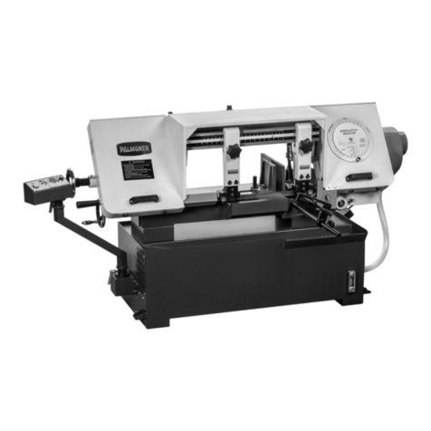
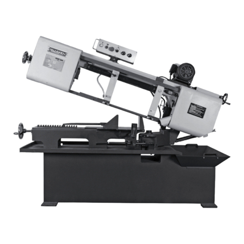
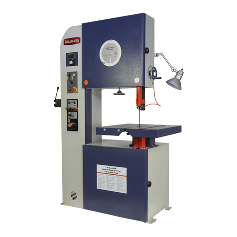
Palmgren 9683120 User manual

Operating Manual & Parts List 9683120 & 9683121
20˝
Tool Room Saws
Read carefully and follow all safety rules and operating
instructions before first use of this product.
9645072.01-0620
9683120_9683121_oipm_En011_9645072.01-0620 __ 06-24-2020 . . .

2
Palmgren Operating Manual & Parts List 9683120 & 9683121
GETTING STARTED
STRUCTURAL REQUIREMENTS
Make sure all supporting structures and load attaching devices are
strong enough to hold your intended loads. If in doubt, consult a
qualified structural engineer.
ELECTRICAL REQUIREMENTS
The power supply to Model 9683120 needs to be 220 volt/ 6.5 amp,
three phase,60 Hz.The standard allowable voltage variation is plus or
minus 10%.
The power supply to Model 9683121 needs to be 440 volt/ 3.25 amp,
three phase,60 Hz.The standard allowable voltage variation is plus or
minus 10%.
TOOLS NEEDED:
Standard mechanic’s hand tool set.
UNPACKING
Carton should be handled with care to avoid damage from
dropping, bumping,etc. Store and unpack carton with correct side
up.After unpacking Band Saw,inspect carefully for any damage that
may have occurred during transit.Check for loose, missing or
damaged parts. If any damage or loss has occurred, claim must be
filed with carrier immediately.Check for completeness.Immediately
report missing parts to dealer.
IMPORTANT: Table is coated with a protectant.To ensure proper fit
and operation,remove coating.Coating is easily removed with mild
solvents,such as mineral spirits, and a soft cloth. Avoid getting
solution on paint or any of the rubber or plastic parts. Solvents may
deteriorate these finishes.Use soap and water on paint, plastic or
rubber components.After cleaning,cover all exposed metal surfaces
with a light coating of oil.Paste wax is recommended for table top.
Palmgren model 9683120 and 9683121 are shipped complete in
one box.The band saw comes assembled as one unit.
After unpacking the unit, carefully inspect for any damage that may
have occurred during transit. Check for loose, missing or damaged
parts. Shipping damage claims must be filed with the carrier.
After unpacking the unit, carefully inspect for any damage that may
have occurred during transit. Check for loose, missing or damaged
parts. Shipping damage claims must be filed with the carrier.
All tools should be visually inspected before use, in addition to
regular periodic maintenance inspections.
Be sure that the voltage labeled on the unit matches your power
supply.
UNPACK:
Do not discard packing materials until after machine has been
inspected for damage and completeness.Locate loose parts and set
aside.
INSPECT:
After unpacking the unit, carefully inspect for any damage that may
have occurred during transit. Check for loose, missing or damaged
parts. Shipping damage claims must be filed with the carrier.
All tools should be visually inspected before use, in addition to
regular periodic maintenance inspections.
Be sure that the voltage labeled on the unit matches your power
supply.
SAFETY RULES
WARNING: For your own safety,read operating instructions manual
before operating tool.
PROPOSITION 65 WARNING: Some dust created by using power tools
contain chemicals known to the state of California to cause cancer,
birth defects or other reproductive harm.
Some examples of these chemicals are:
• Lead from lead-based paints
• Crystalline silica from bricks and cement and other masonry
products.
• Arsenic and chromium from chemically treated lumber.
Your risk from these exposures varies,depending on how often you
do this type of work.To reduce your exposure to these chemicals;
work in a well ventilated area and work with approved safety
equipment.Always wear OSHA/NIOSH approved, properly fitting
face mask or respirator when using such tools.
WARNING: Always follow proper operating procedures as defined in
this manual even if you are familiar with the use of this or similar tools.
Remember that being careless for even a fraction of a second can
result in severe personal injury.
BE PREPARED FOR JOB
• Wear proper apparel.Do not wear loose clothing, gloves,
neckties,rings, bracelets or other jewelry which may get caught
in moving parts of machine.
• Wear protective hair covering to contain long hair.
• Wear safety shoes with non-slip soles.
• Wear safety glasses complying with United States ANSI Z87.1.
Everyday glasses have only impact resistant lenses.They are NOT
safety glasses.
• Wear face mask or dust mask if operation is dusty.
• Be alert and think clearly.Never operate power tools when tired,
intoxicated or when taking medications that cause drowsiness.
PREPARE WORK AREA FOR JOB
• Keep work area clean.Cluttered work areas invite accidents.
• Do not use power tools in dangerous environments.Do not use
power tools in damp or wet locations. Do not expose power
tools to rain.
• Work area should be properly lighted.
• Proper electrical receptacle should be available for tool.Three-
prong plug should be plugged directly into properly grounded,
three-prong receptacle.
• Extension cords should have a grounding prong and the three
wires of the extension cord should be of the correct gauge.
• Keep visitors at a safe distance from work area.
• Keep children out of workplace.Make workshop childproof.Use
padlocks,master switches or remove switch keys to prevent any
unintentional use of power tools.
9683120_9683121_oipm_En011_9645072.01-0620 __ 06-24-2020 . . .

3
Palmgren Operating Manual & Parts List 9683120 & 9683121
SAFETY RULES (CONTINUED)
TOOL SHOULD BE MAINTAINED
• Always unplug tool prior to inspection.
• Consult manual for specific maintaining and adjusting
procedures.
• Keep tool lubricated and clean for safest operation.
• Remove adjusting tools. Form habit of checking to see that
adjusting tools are removed before switching machine on.
• Keep all parts in working order.Check to determine that the
guard or other parts will operate properly and perform their
intended function.
• Check for damaged parts. Check for alignment of moving parts,
binding,breakage,mounting and any other condition that may
affect a tool’s operation.
• A guard or other part that is damaged should be properly
repaired or replaced.Do not perform makeshift repairs.(Use
parts list provided to order repair parts.)
KNOW HOW TO USE TOOL
• Use right tool for job.Do not force tool or attachment to do a job
for which it was not designed.
• Disconnect tool when changing the blade.
• Avoid accidental start-up.Make sure that the tool is in the OFF
position before plugging in.
• Do not force tool.It will work most efficiently at the rate for
which it was designed.
• Keep hands away from moving parts and cutting surfaces.
• Never leave tool running unattended.Turn the power off and do
not leave tool until it comes to a complete stop.
• Do not overreach.Keep proper footing and balance.
• Never stand on tool.Serious injury could occur if tool is tipped or
if blade is unintentionally contacted.
• Know your tool.Learn the tool’s operation, application and
specific limitations.
• Use recommended accessories. Use of improper accessories may
cause risk of injury to persons.
• Handle workpiece correctly.Protect hands from possible injury.
• Turn machine off if it jams.Blade jams when it digs too deeply
into workpiece.(Motor force keeps it stuck in the work.) Do not
remove jammed or cut off pieces until the saw is turned off,
unplugged and the blade has stopped.
• Maintain proper adjustment of blade tension,blade guides and
thrust bearings.
• Adjust upper guide to just clear workpiece.
• Hold workpiece firmly against table.
• Direction of feed:Feed work into a blade or cutter against the
direction of rotation of the blade or cutter only.
WARNING: The operation of any power tool can result in foreign
objects being thrown into the eyes, which can result in severe eye
damage.Always wear safety goggles complying with United States
ANSI Z87.1 (shown on package) before commencing power tool
operation.
SPECIFICATIONS
9683120 9683121
Blade Length 157˝ 157˝
Blade Width 1/4˝ – 3/4˝ 1/4˝ – 3/4˝
Blade Thickness .032˝ .032˝
HP 3 HP 3 HP
Voltage 220V 440V
Amperage 6.5A 3.25A
Phase 3 PH 3 PH
Cutting Capacity Rectangle 12˝×20˝ 12˝×20˝
Cutting Capacity Round 12˝ 12˝
Cutting Capacity Square 12˝ 12˝
Table Height 38.5˝ 38.5˝
Table Tilt 45° right; 15° left 45° right; 15° left
Blade to Frame 12˝ 12˝
Electric Welder 4.2 kVA 4.2 kVA
Grinder Motor 1/8 HP 1/8 HP
Machine Dimensions 46.5˝×38.5˝ ×77˝ 46.5˝×38.5˝ ×77˝
Weight 1300 lbs 1301 lbs
Speeds 0–2500 SFPM 0–2500 SFPM
Table Dimensions 21.5˝×23.5˝ 21.55˝×23.5˝
Blade Wheels Diameter 20˝ 20˝
INSTALLATION
POWER SOURCE
Model 9683120 is wired for 220 volt, 60 Hz power source.
Model 9683121 is wired for 440 volt, 60 Hz power source.
The motor is designed for operation on the voltage and frequency
specified.Normal loads will be handled safely on voltages not more
than 10% above or below the specified voltage.
Running the unit on voltages which are not within the range may
cause overheating and motor burn-out.Heavy loads require that the
voltage at motor terminals be no less than the voltage specified.
Power supply to the motor is controlled by a single pole toggle
switch.
WARNING: Improper connection of equipment grounding conductor
can result in the risk of electrical shock. Equipment should be
grounded while in use to protect operator from electrical shock.
• Check with a qualified electrician if grounding instructions are
not understood or if in doubt as to whether the tool is properly
grounded.
• Inspect tool cords periodically,and, if damaged, have repaired by
an authorized service facility.
WARNING: Do not permit fingers to touch the terminals of plug when
installing or removing from outlet.
9683120_9683121_oipm_En011_9645072.01-0620 __ 06-24-2020 . . .

4
Palmgren Operating Manual & Parts List 9683120 & 9683121
INSTALLATION (CONTINUED)
EXTENSION CORDS
• The use of any extension cord will cause some drop in voltage
and loss of power.
• Wires of the extension cord must be of sufficient size to carry the
current and maintain adequate voltage.
• Running the unit on voltages which are not within ±10% of the
specified voltage may cause overheating and motor burn-out.
• Use the table to determine the minimum wire size (A.W.G.)
extension cord.
• Use only 3-wire extension cords having 3-prong grounding type
plugs and 3-pole receptacles which accept the tool plug.
• If the extension cord is worn,cut or damaged in any way, replace
it immediately.
OPERATION
CONTROLS
Refer to Figures 1,2 and 3.
Figure 1 – Controls
A. Speed Readout – Displays speed in feet per minute.
B. Speed Selection Dial – Variable speed control.
C. Power Switch – Main power control with key.
D. Power Lamp – Lights up if power is getting to the machine.
E. Saw Motor/Blade Welder Switch – Switches power between
band saw motor and blade welder. (The saw motor and blade
welder cannot operate at the same time.)
F. Start – Starts the saw motor.
G. Emergency Stop – Stops the machine quickly.To reset,twist and
pull the knob to allow motor to be reactivated.
Figure 2 – Controls
H. Blade Guide Up and Down Handwheel
I. Blade Guide
J. Blade Tension Handwheel
Figure 3 – Controls
K.Blade Tracking Knob
L.Blade Guide Lock Knob
Volts
120 25 50 100 150
240 50 100 150 300
0 6 18 16 16 14
6 10 18 16 14 12
10 12 16 16 14 12
12 16 14 12
More Not
Than More Than Minimum Gage for Cord
Total Length of Cord in Feet
Not Recommended
Ampere Rating
Extension Cord Table
B
A
C
D
E
F
G
H
I
J
K
L
9683120_9683121_oipm_En011_9645072.01-0620 __ 06-24-2020 . . .

5
Palmgren Operating Manual & Parts List 9683120 & 9683121
OPERATION (CONTINUED)
INSTALLING/REPLACING BLADE
WARNING: Ensure the saw is disconnected from power supply, so
there is no possibility of saw activation!
WARNING: When handling blades always wear thick work gloves.
REMOVE SAW BLADE
1. Open upper and lower cabinets
2. Loosen Blade tension handle“J”.Beware the blade does not
spring off the wheel
3. Start with the upper section and remove the saw blade from the
top of the wheel
4. Work the saw blade out of the blade guide“I”
5. Slide the saw blade through the table slit
6. Remove the rest of the saw blade from around the lower wheel.
INSTALL NEW SAW BLADE
1. Start by wrapping the new saw blade around the lower wheel.
Ensure the blade teeth are facing towards you and down
towards the table..
2. Slide the new blade through the table slit
3. Slide the new saw blade through the long slit in the blade guide“I”
4. Wrap the new blade around the top of the upper wheel.
5. Finish by re-tensioning the upper wheel using the handwheel“J”.
BLADE WELDING
The control panel for the blade welder is shown in Figure 4.The
welding circuitry is energized independent of the band saw
circuitry.
To operate the welder,plug in the line cord to a proper power
source.
CAUTION: Do not operate the band saw and the welder at the same
time.
Figure 4 – Blade welder controls.
PREPARING BLADE FOR WELDING
1. A properly prepared blade is essential in producing a high-
quality, long lasting band saw blade.
2. The blade must be cut to proper length.
3. Blade ends should be cut and ground square.
4. Any rust, oil or dirt must be removed.
5. Some teeth must be ground off blade ends depending upon the
pitch of the blade.
BLADE CUTTING
Refer to Figure 5.
1. Cut the blade ends flat, square and smooth using the blade
shear.
2. Lean the back of blade against the shear blade guide when
cutting blade ends (See Figure 5).
3. Use grinder, as needed, to make blade ends flat, square and
smooth.
Figure 5 – Blade cutting.
Anneal
Button
Weld
Button
Movable
Jaw
Weld Pressure
Adjustment
Knob
Stationary Jaw
Jaw Clamping
Handles
Grinder
Switch
Butt back of blade against
shear alignment surface.
9683120_9683121_oipm_En011_9645072.01-0620 __ 06-24-2020 . . .

6
Palmgren Operating Manual & Parts List 9683120 & 9683121
OPERATION (CONTINUED)
BLADE MOUNTING
Refer to Figure 6.
1. Clean welder jaw of any scale,oil, rust or dirt. Clean blade ends
which contact welder jaws to provide proper electrical contact.
2. Set weld pressure adjustment knob to "0" (released).
3. Insert one end of blade into stationary jaw with teeth facing out
and blade end centered between jaws.
4. Firmly set back of blade against back alignment surface of
welder jaw and clamp blade tight with the jaw clamping handle
(See Figure 6).
5. Insert other end of blade into movable jaw; butt the blade ends
together and clamp tight.
IMPORTANT: The blade ends should butt against each other over
the full width of the blade and should not overlap (See Figure 6).
Figure 6 –Blade mounting and clamping.
TOOTH SPACING
Refer to Figure 7.
1.Approximately 1/8”of blade will be consumed during the welding
process.This blade loss must be taken into account.
2.All blades must have some of the teeth ground off so that the
tooth spacing will be uniform after welding.
3.Tooth grinding procedure must be done carefully in order to grind
the proper number of teeth and not to grind below gullet which
would weaken the blade.
Figure 7 – Tooth spacing (TPI = teeth per inch).
BLADE WELDING
Refer to Figure 8.
1. To set weld pressure adjustment knob,turn the knob
counterclockwise to increase the pressure.The pressure
adjustment knob controls force applied to the movable jaw.
NOTE: Weld pressure adjustment knob must be reset to“0”after
each welding.
2. Wider blades and thicker blades need more weld pressure to
force the blade ends together during welding.If too little
pressure is applied, the blade ends will melt.Too much pressure
may cause the blades to overlap.
For example, for 1/2" wide blades, turn the pressure adjustment
knob counterclockwise until the pointer is at 6 (See Figure 8).
Figure 8 – Weld Pressure Adjustment
3. If blade melts, increase pressure.If there are "blow holes" in the
weld, increase pressure.
4. If blade overlaps,decrease pressure.
5. Wider blades need more pressure and thinner blades need less
pressure.Weld pressure is also affected by blade material.
Correct – Grind Blades Square and Clamp Straight
Correct – Clamp Blades Flat with no Overlap
Incorrect – Blades Clamped At Angle
Incorrect – Blades Not Ground Square
Incorrect – Blades Overlap
4TPI
6TPI
8TPI
10
TPI
20
TPI
12TPI
16TPI
1/4
Tooth
1/4
Tooth
3/8
Tooth
3/8
Tooth
1/2
Tooth
1/2
Tooth
5/8
Tooth
5/8
Tooth
1¼
Tooth
1¼
Tooth
3/4
Tooth
3/4
Tooth
3/4
Tooth
3/4
Tooth
01
2
3
4
5
6
7
8
9
9683120_9683121_oipm_En011_9645072.01-0620 __ 06-24-2020 . . .

7
Palmgren Operating Manual & Parts List 9683120 & 9683121
OPERATION (CONTINUED)
WARNING: Welding operation produces sparks at blade intersection.
Step away to left side of welder during welding operation.
WARNING: Always wear ANSI approved safety glasses during welding.
Sparks from welder can cause serious injury to eyes.
6. Press weld button and hold down.The blade ends will become
red hot and soft.The movable jaw will force the blade ends
together creating a bead of metal and the limit switch will
automatically cut power to jaws.
7. Release weld button and wait 10 seconds to allow blade to cool.
8. Reset weld pressure adjustment to“0”.
9. Heat build-up in the tool can cause serious damage to the tool.
Allow transformer to cool down to room temperature between
each welding or each annealing operation.It is a safe procedure
to let the transformer be idle for at least 3 minutes between
successive welding/annealing operations.
BLADE ANNEALING
1. After the blade has been welded,the weld area will be very hard
and brittle.Before the blade can be used,it must be annealed
and the flash removed.
2. The blade weld is annealed by heating the blade just under the
melting temperature and then slowly cooling the weld.
NOTE: Reset weld pressure adjustment knob to“0”prior to
annealing.Failure to do so can cause damage to transformer.
3. Press the anneal button until the weld area glows a cherry red
and then release the anneal button.
CAUTION: The blade weld will melt, destroying the weld, if the anneal
button is not released as soon as the weld glows cherry red.
4. Let the blade cool for several seconds.
5. Press the anneal button again,but release the button before the
weld glows as brightly as the first time.
6. Wait several seconds until the blade cools further.
7. Repeat the anneal process 6 or 7 times,decreasing the anneal
temperature each time.
8. The weld flash must be ground from the blade.See“Grinding
Blade”.
GRINDING BLADE
1. After annealing the blade, the metal buildup or flash must be
ground from the blade.
2. Toggle grinder switch to the ON position.
3. Flip the grinder guard open, exposing the top of the grinding
wheel.
4. Weld should be ground to same thickness as blade.
5. Grind flash off under-side of blade taking care not to grind into
blade.
6. Turn blade inside out and grind other side of blade same as first
side (or,flip the grinder guard to the closed position and use the
bottom of the wheel).
7. Take care not to grind into blade.
8. Turn blade inside out again (to original shape).
9. Turn grinder off when grinding is completed.The blade must be
annealed again.
ANNEAL BLADE AFTER GRINDING
1. After flash has been removed, anneal the blade a second time.
The weld may have been hardened by heat created during
grinding.Repeat“Blade Annealing”step.
2. After second blade annealing operation, the blade is ready for
installation onto band saw.Follow band saw instruction when
installing and adjusting blade.
MAINTENANCE
Steps required to keep the saw in optimum operating condition
have been described under“Operating Instructions.”The Safety
Precautions should be performed before operation.
For proper maintenance:
• Keep saw clean and dry. Sweep off spots where chips have
collected.
• Lubricate the unpainted surfaces with a light application of
medium consistency machine oil to prevent corrosion after
cleaning.
• Replace dull blades and blades from which teeth have been
stripped.A clean saw with a sharp blade will yield the best cut.
• Internal parts of the band saw have been completely lubricated
at the factory and do not need to be relubricated.
WARNING: Make certain that the saw is disconnected from the power
source before attempting to service or remove any component.
9683120_9683121_oipm_En011_9645072.01-0620 __ 06-24-2020 . . .

8
Palmgren Operating Manual & Parts List 9683120 & 9683121
RST
M1 U
V
W
M1
M1
M2
R
S
T
U
V
W
T2
0V
R1
220V
2
M1
8
5
7
P6R1
L
RPM
Light 8
9
10
4
M1
M2
R
R
11
1312 14
RGFWD
TG1 TG2
R2
Motor
Weld
M2
24V
Figure 9 – 9683120 electrical diagram, 220V.
220 V ELECTRICAL DIAGRAM
9683120_9683121_oipm_En011_9645072.01-0620 __ 06-24-2020 . . .

9
Palmgren Operating Manual & Parts List 9683120 & 9683121
RST
M1 U
V
W
M1
M1
M2
R
S
T
U
V
W
T2
0V
R1
220V
2
M1
8
5
7
P6R1
L
RPM
Light 8
9
10
4
M1
M2
R
R
11
1312 14
RGFWD
TG1 TG2
R2
Motor
Weld
24V
M2
M2 S2
Figure 10 – 9683121 electrical diagram, 440 V.
440 V ELECTRICAL DIAGRAM
9683120_9683121_oipm_En011_9645072.01-0620 __ 06-24-2020 . . .

10
Palmgren Operating Manual & Parts List 9683120 & 9683121
14
16
17
15
18
18-1
21
22
24 25
23
20
19
20
26
11
910
13
7
8
12
2
4-1
3
4-3
4-4
4-2
4
56
19
1
27
28
Figure 11 – Repair parts illustration for cabinet.
9683120_9683121_oipm_En011_9645072.01-0620 __ 06-24-2020 . . .

1 Wheel Door Lower 9645365.01 1
2 Hinge Pin Lower 9645366.01 2
3 Phillips Head Screw M5× 0.8×8mm * 4
4 Control Panel 9645367.01 1
4-1 Power Switch On/Off Button 9645368.01 1
4-2 Power Lamp 9645369.01 1
4-3 Selector Switch Button 9645370.01 1
4-4 Motor On/Off Button 9645371.01 1
4-5 Emergency Stop Button 9645372.01 1
5 Blade Cleaning Brush 9645373.01 1
6 Phillips Head Screw M6× 1.0P×25mm * 1
7 Wheel Door Upper 9645374.01 1
8 Hinge Pin Upper 9645375.01 2
9 Phillips Head Screw M5× 0.8×8mm * 4
10 Digital Display Bracket 9645376.01 1
11 Cap Screw M8× 1.25P×16mm * 2
12 Blade Shear 9645377.01 1
13 Variable Speed Dial 9645378.01 1
14 Air pump 9645379.01 1
15 Band Saw Cabinet 9645380.01 1
16 Air Hose 4× 6mm N/A 1
17 Air Nozzle 9645381.01 1
18 Work Lamp 220V 9645382.01 1
18-1 Light Bulb 220V 9645383.01 1
19 Door Knob 9645384.01 2
20 Phillips Head Screw M6× 1.0P×15mm * 2
21 Cap Screw M6× 1.0P×15mm * 4
22 Flat Washer 6mm * 4
23 Motor Access Panel 9645385.01 1
24 Flat Washer 6mm * 10
25 Hex Bolt M6× 1.0P×10mm * 10
26 Chip Pan 9645386.01 1
27 Inverter 9645416.01 1
28 Control Panel 2 9645417.01 1
11
Palmgren Operating Manual & Parts List 9683120 & 9683121
Ref.
No. Description Part Number: Qty.
(Δ) Not shown.
(N/A) Not available as repair part.
(*) Standard hardware item, available locally.
REPLACEMENT PARTS LIST FOR CABINET
9683120_9683121_oipm_En011_9645072.01-0620 __ 06-24-2020 . . .

12
Palmgren Operating Manual & Parts List 9683120 & 9683121
Figure 12 – Repair parts illustration for table and lower guide.
7
4
5
8
9
10
11
12
16 15
17
14 13
15
16
6
2
1
3
14
9683120_9683121_oipm_En011_9645072.01-0620 __ 06-24-2020 . . .

1 Table 9645387.01 1
2 Fixing Screw 9645388.01 1
3 Tilting (Seat L.R) 9645389.01 1
4 Washer M8 * 4
5 Hex Socket Cap M8×1.25P ×20mm * 4
6 Trunnion Base 9645390.01 1
7 Hex Bolt M8×1.25P ×20mm * 4
8 Washer M8 * 4
9 M10 Washer * 4
10 Hex Nut M10× 1.5P * 4
11 Lower Guide Rod 9645391.01 1
12 Hex Socket Cap x2 M6× 1.0P×25mm * 2
13 Guide Seat (Lower) 9645392.01 1
14 Tungsten Support 9645393.01 2
15 M6 Washer * 2
16 Hex Socket Cap M6× 1.0P×20mm * 2
17 Blade Support 9645394.01 1
13
Palmgren Operating Manual & Parts List 9683120 & 9683121
Ref.
No. Description Part Number: Qty.
(Δ) Not shown.
(N/A) Not available as repair part.
(*) Standard hardware item, available locally.
REPLACEMENT PARTS LIST FOR TABLE AND LOWER GUIDE
9683120_9683121_oipm_En011_9645072.01-0620 __ 06-24-2020 . . .

14
Palmgren Operating Manual & Parts List 9683120 & 9683121
Figure 13 – Repair parts illustration for motor and lower wheel.
18
15
16
10
17
11
13
14
13
12
1
2
2
9
11
4
4
7
6
8
5
3
3
19
9683120_9683121_oipm_En011_9645072.01-0620 __ 06-24-2020 . . .

1 Wheel Lower 9645395.01 1
2 Hex Bolt M10×1.5P ×10mm * 2
3 Bearing 6206 * 2
4 Key 8×8 ×20 * 2
5 Lower Wheel Shaft 9645399.01 1
6 Special Screw 9645398.01 1
7 Hex Bolt M10×1.5P ×50mm * 1
8 Bearing Housing 9645397.01 1
9 Retaining Ring STW30# * 1
10 Wheel Pulley 9645400.01 1
11 Set Screw M12× 1.75×35mm * 2
12 Motor Pulley 9645401.01 1
13 Set Screw M8× 1.25P×10mm * 2
14 Motor 2HP 220v 3ph 9645402.01 1
14 Motor 2HP 440v 3ph 9645465.01 1
15 Hex Bolt M8× 1.25P×25mm * 2
16 V-Belt A57 x2 9645403.01 1
17 Base of Gear Reducer 9645404.01 1
18 Nut M8× 1.25P * 2
19 Collar and M8-1.75× 8 Set Screw 9645466.01 1
15
Palmgren Operating Manual & Parts List 9683120 & 9683121
Ref.
No. Description Part Number: Qty.
(Δ) Not shown.
(N/A) Not available as repair part.
(*) Standard hardware item, available locally.
REPLACEMENT PARTS LIST FOR MOTOR AND LOWER WHEEL
9683120_9683121_oipm_En011_9645072.01-0620 __ 06-24-2020 . . .

16
Palmgren Operating Manual & Parts List 9683120 & 9683121
Figure 14 – Repair parts illustration for upper wheel.
2
2
7
13
15
29
23
18
17
27
26
25
16
12
15
14
1
16
8910 17
9
21
20
18
3
34
5
6
4
10
8
22 24
9683120_9683121_oipm_En011_9645072.01-0620 __ 06-24-2020 . . .

1 Wheel Upper 9645405.01 1
2 Hex Bolt M10×1.5P ×10mm * 2
3 Retaining Ring STW-30# * 2
4 Bearing 6206 * 2
5 Bearing Housing 9645406.01 1
6 Upper Wheel Shaft 9645407.01 1
7 Key 8 x 8 x 20 * 1
8 Lock Washer 3/8 * 2
9 Hex Nut 3/8 * 2
10 Hex Bolt 3/8-16× 1-1/2 * 2
11 Upper Wheel Bracket 9645409.01 1
12 Pivot Pin 9645408.01 2
13 Hex Bolt M8× 1.25P×25mm * 4
14 Flat Washer 8mm * 4
15 Bracket Plate 9645410.01 2
16 Set Screw M6× 1.0P×6mm * 2
17 Collar 9645412.01 2
18 Thrust Bearing 2901 9645413.01 2
19 Tensioning Bracket 9645411.01 1
20 Leadscrew Bracket 9645415.01 1
21 Hex Bolt M8× 1.25P×25mm * 2
22 Hex Bolt M8× 1.25P×10mm * 1
23 Tension Leadscrew 9645414.01 1
24 Tensioning Handwheel 9645418.01 1
25 Lock Knob (Large) M10× 1.5P 9645421.01 1
26 Lock Knob (small) M10× 1.5P 9645420.01 1
27 Tube 9645419.01 1
28 Bearing Bracket N/A 1
29 Tension Bracket N/A 1
17
Palmgren Operating Manual & Parts List 9683120 & 9683121
Ref.
No. Description Part Number: Qty.
(Δ) Not shown.
(N/A) Not available as repair part.
(*) Standard hardware item, available locally.
REPLACEMENT PARTS LIST FOR UPPER WHEEL
9683120_9683121_oipm_En011_9645072.01-0620 __ 06-24-2020 . . .

18
Palmgren Operating Manual & Parts List 9683120 & 9683121
Figure 15 – Repair parts illustration for guide post.
9683120_9683121_oipm_En011_9645072.01-0620 __ 06-24-2020 . . .

1 Hexagon Socket Bolt M6×1P ×20L * 2
2 Flat Washer 6mm * 2
3 Tungsten Support 9645422.01 2
4 Guide Seat (Upper) 9645423.01 1
5 B1 Tungsten Bar Crown (Upper) 9645424.01 1
6 Hexagon Socket Bolt M6×1P ×20L * 2
7 Pin 4× 6 * 2
8 Ascending/Descending Fixing Plate 9645425.01 1
9 Ascending/Descending Guide Rod 9645426.01 1
10 Ascending/Descending Bracket 9645427.01 1
11 Lock Washer 14mm * 3
12 Lock Knob 9645428.01 1
13 Screw Worm 9645429.01 1
14 Gear Worm 9645430.01 1
15 Worm Shaft 9645431.01 1
16 Collar 9645432.01 1
17 Handle 9645433.01 1
18 Handwheel 9645434.01 1
19 Pin Spring * 1
20 Support Worm Gear 9645435.01 1
21 Spring Washer * 2
22 Hexagon Socket Bolt M6×1P ×20L * 2
23 Guard Blade Upper 9645436.01 1
24 Washer Flat, 8mm * 1
25 Cap Screw M8-1.25× 115 * 1
19
Palmgren Operating Manual & Parts List 9683120 & 9683121
Ref.
No. Description Part Number: Qty.
(Δ) Not shown.
(N/A) Not available as repair part.
(*) Standard hardware item, available locally.
REPLACEMENT PARTS LIST FOR GUIDE POST
9683120_9683121_oipm_En011_9645072.01-0620 __ 06-24-2020 . . .

20
Palmgren Operating Manual & Parts List 9683120 & 9683121
Figure 16 – Repair parts illustration for welding station.
9683120_9683121_oipm_En011_9645072.01-0620 __ 06-24-2020 . . .
This manual suits for next models
1
Table of contents
Other Palmgren Saw manuals

Palmgren
Palmgren 83115 User manual

Palmgren
Palmgren 83116 Installation and operation manual

Palmgren
Palmgren 9683408 User manual

Palmgren
Palmgren 9684486 Instructions for use

Palmgren
Palmgren 9683338 Instructions for use

Palmgren
Palmgren 83118 User manual

Palmgren
Palmgren PALM9683295 User manual

Palmgren
Palmgren CS 250 User manual

Palmgren
Palmgren 9683315 Instructions for use

Palmgren
Palmgren 9683122 User manual