Palstar AT5K User manual

© Copyright 2006 Palstar Inc.
Printed in the U.S.A. Rev. 1.1
AT5K 3500 Watt Antenna Tuner
Owner’s Manual

1-800-773-7931 WWW.PALST AR.COM
2 Important Safeguards
WARNING: TO PREVENT FIRE OR
ELECTRICAL SHOCK DO NOT
EXPOSE TO RAIN OR MOISTURE
1. Read Instructions—All the safet and
operating instructions should be read before
the appliance is operated.
2. Retain Instructions—The safet and
operating instructions should be retained for
future reference.
3. Heed Warnings—All warnings on the
appliance should be adhered to.
4. Follow Instructions—All operating and
use instructions should be followed.
5. Cleaning—Unplug this appliance from the
wall outlet before cleaning. Do not use liquid
cleaners or aerosol cleaners. Use a damp
cloth for cleaning.
6. Do Not Use ttachments—not recom-
mended b the manufacturer or the ma
cause hazards.
7. Water and Moisture—Do not use this
product near water—for example, near a
bathtub, wash bowl, kitchen sink, laundr tub,
in a wet basement, or near a swimming pool—
and the like.
8. ccessories—Do not place this product on
an unstable cart, stand, tripod, bracket, or
table. The product ma fall, causing serious
injur to a child or adult, and serious damage
to the appliance.
9. Ventilation—This product should never be
placed near or over a radiator or heat register.
This product should not be placed in a built-in
installation such as a bookcase or rack unless
proper ventilation is provided or the manufac-
turer’s instructions have been adhered to. An
slots or openings in the cabinet are provided
for ventilation. To ensure reliable operation of
the video product and to protect it from over-
heating, these openings must not be blocked
or covered. The openings should never be
blocked b placing the product on a bed, sofa,
rug, or other similar surface.
10. Grounding or Polarization—this product
is equipped with a 3-wire line cord receptacle.
It is intended for use with a 3-wire properl
grounded power socket. Do not defeat the
safet purpose of the supplied line cord and
plug.
11. Power Sources—This product should be
operated onl from the t pe of power source
indicated on the marketing label. If ou are not
sure of the t pe of power supplied to our
home, consult our appliance dealer or local
power compan .
12. Power-cord Protection—Power-suppl
cords should be routed so the are not likel
to be walked on or pinched b items placed
upon or against them. Pa particular attention
to cords at plugs, convenience receptacles,
and the point where the exit.
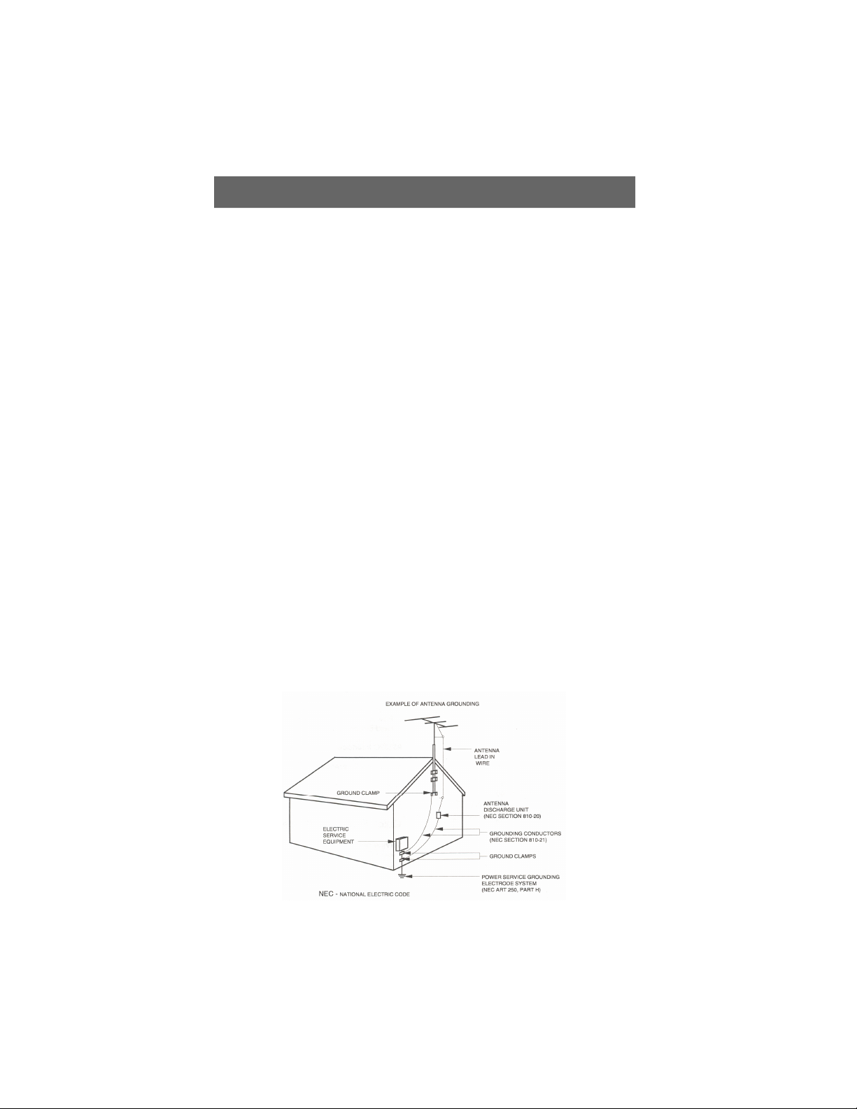
13. Lightning—For added protection for this
product during a lightning storm, or when it is
left unattended and unused for long periods of
time, unplug it from the wall outlet.
WARNING: TO REDUCE THE RISK OF FIRE OR ELECTRIC SHOCK, DO NOT
EXPOSE THIS APPLIANCE TO RAIN OR MOISTURE. DO NOT
OPEN THE CABINET WHILE OPERATING. REFER SERVICING TO
QUALIFIED PERSONNEL ONLY.
CAUTION: TO PREVENT ELECTRIC SHOCK, DO NOT USE THE THREE WIRE
CORD WITH AN EXTENSION CORD RECEPTIACLE OR OTHER
OUTLET UNLESS THE BLADES CAN BE FULLY INSERTED TO
PREVENT BLADE EXPOSURE.
An appliance and cart combination should
be moved with care. Quick stops, exces-
sive force and uneven surfaces ma cause
the appliance and cart combination to
overturn.
The lightning flash with arrow head
s mbol, within an equilateral triangle, is
intended to alert the user to the presence
of uninsulated “dangerous voltage” within
the product’s enclosure that ma be of
sufficient magnitude to constitute a risk of
electric shock to persons.
The exclamation point within an equilateral
triangle is intended to alert the user to the
presence of important operating and
maintenance (servicing) instructions in the
literature accompan ing the appliance.

1-800-773-7931 WWW.PALST AR.COM
Important Safeguards cont’d 3
14. Power Lines—An outside antenna s s-
tem should not be located in the vicinit of
overhead power lines, other electric light or
power circuits, where it can fall into such
power lines or circuits. When installing an
outside antenna s stem, extreme care should
be taken to keep from touching such power
lines or circuits as contact with them ma be
fatal.
15. Overloading—Do not overload wall out-
lets and extension cords as this can result in a
risk of fire or electric shock.
16. Object and Liquid Entry—Never push
objects of an kind into this product through
openings as the ma touch dangerous volt-
age points or short-out parts that could result
in a fire or electric shock. Never spill liquid of
an kind on the product.
17. Servicing—Do not attempt to service this
product ourself as opening or removing
covers ma expose ou to dangerous voltage
or other hazards. Refer all servicing to quali-
fied service personnel.
18. Damage Requiring Service—Unplug this
product from the wall outlet and refer servicing
to qualified service personnel under the fol-
lowing conditions:
a. When the power-suppl cord or plug is
damaged.
b. If liquid has been spilled, or objects have
fallen into the product.
c. If the product has been exposed to rain or
water.
d. If the product does not operate normall b
following the operating instructions. Adjust
onl those controls that are covered b the
operating instructions. An improper adjust-
ment ma result in damage and will often
require extensive work b a qualified
technician to restore the product to its normal
operation.
e. If the product has been dropped or the
cabinet has been damaged.
f. When the product exhibits a distinct change
in performance—this indicates a need for
service.
19. Replacement Parts—when replacement
parts are required, be sure the service techni-
cian has used replacement parts specified b
the manufacturer or have the same character-
istics as the original parts. Unauthorized sub-
stitutes ma result in fire, electric shock or
other hazards.
20. Safety Checks—Upon completion of an
service or repairs to this product, ask the
service technician to perform safet checks to
determine that the product is in proper operat-
ing condition.
21. Outdoor ntenna Grounding—Before
attempting to install this product, be sure the
antenna or cable s stem is grounded so as to
provide some protection against voltage
surges and built-up static charges.
a. Use No.10 AWG copper, No.8AWG alumi-
num, No.17AWB copper-clad steel or bronze
wire or larger, as ground wire.
b. Secure antenna lead-in and ground wires to
house with stand-off insulators spaced from 4
feet to 6 feet apart.
c. Mount antenna discharge unit as close as
possible to where lead-in enters house.
d. A driven rod ma be used as the grounding
electrode where other t pes of electrode
s stems do not exist. Refer to the National
Electric Code, ANSI/NFPA 70-1990 for infor-
mation.
e. Use jumper wire not smaller than No.6
AWG copper or equivalent, when a separate
antenna grounding electrode is used.

4 Table of Contents
1-800-773-7931 WWW.PALST AR.COM
Important safeguards 2
Table of Contents 4
General Description 5
Specifications 6
Installation 7
Unpacking 7
Location 7
Installation Procedures 7
AT5K Schematic 8
Rear Panel Connections 10
Front Panel Description 11
Operating Your T5K 12
Before Operating 12
Tuning 12
Notes 14
Service and Warranty 15
Thank ou for purchasing a
Palstar AT5K Antenna Tuner.
This antenna tuner has been
designed and manufactured to
high qualit standards, and will
provide reliable operation for
man ears.
Please carefull read the
Owner’s Manual in order to take
advantage of the man interest-
ing features that will provide
ears of enjo able amateur
radio operation.

General Description 5
1-800-773-7931 WWW.PALST AR.COM
The Palstar AT5K Antenna
Tuner is an American made im-
pedance matching network that
can provide unbalanced and
balanced output with a power
rating of 3500 watts (single tone
continuous) and 5000 watts
PEP at certain Z ranges (p.14).
The AT5K T-matching network
utilizes a 1:1 unbalanced to bal-
anced transformer in the input of
the network. When the network
is properl tuned, a 50 Ohm im-
pedance will be presented to
both the input and output of the
balun for maximum efficienc .
The AT5K optimizes the per-
formance of our antenna and
transmitter b providing adjust-
able impedance matching using
a T-t pe circuit configuration.
The AT5K also measures the
power and Voltage Standing
Wave Ratio (VSWR) which al-
lows ou to tune the SWR to the
lowest ratio for the selected
transmission frequenc .
Integrated into the AT5K is a
frequenc -compensated lighted-
dial dual-movement SWR me-
ter. The meter features the abil-
it to read True Active Peak and
Peak Hold.
Designed to handle both Bal-
anced line feeds and Coax
feeds the AT5K features a front
panel mounted switch to select
between feeds.
Tuning is achieved with the front
panel mounted controls. The
Vernier capacitor dials allow for
tuning with precision and accu-
rac , while the Inductor crank
handle facilitates coarse adjust-
ments.

6 Specifications
1-800-773-7931 WWW.PALST AR.COM
Front Panel Indicators and Controls
Metering Dual movement cross needle power and frequenc
compensated coupler
Controls
Input Tuning Variable capacitor (600 pF, 6kV Peak)
Antenna Tuning Variable capacitor (600 pF, 6kV Peak)
Inductance 35 µH roller inductor 10 ga. plated copper wire
rated at 10 amps and 5kV
Antenna Selector Switch 6 position: Coax 1 tuned and tuner
B pass, Coax 2 tuned and tuner
B pass; B pass and balanced antenna
Switch wafers are ceramic (7kV/10A rated)
Power Range Switch 2 position 300 W /3000 W
Rear Panel Connectors
Coax 1 SO239 connector (silver/gold/TFE)
Coax 2 SO239 connector (silver/gold/TFE)
B pass SO239 connector (silver/gold/TFE)
RF INPUT SO239 connector (silver/gold/TFE)
Balanced Line Dual High Voltage N lon66TM terminal post
12 VDC Input Adaptor for meter light 2.1 mm con. (center positive)
Other
Frequenc Coverage 1.8 — 29.5 MHz
Power Maximum 5000 W PEP SSB, 3500 W single tone continuous
Impedance Range 10 to 2000Ω NOTE: Power Range p.14
Balanced Output 1:1 current t pe Balun at input-Ferrite
Dimensions 8”H x 16”W x 18”D (incl. terminals)
Weight 25 lbs.
Materials Chassis, brackets, and top cover are gold chem-film
coated aluminum (.090) & powder coated.
Front Panel Front panel is matte powder coated and screened.

W RNING: Balanced antennas will produce high
RF voltages at the output post connectors. RF
burns may result if touched during transmission.
Installation 7
1-800-773-7931 WWW.PALST AR.COM
Unpacking
Carefull remove the AT5K from
the shipping carton and inspect
it for signs of damage. If an
damage is apparent, notif the
transportation carrier or dealer
immediatel . We recommend
keeping the packing carton
for moving, storing or reship-
ping the tuner to us for repair
if required.
Location
Select a location for the AT5K
that allows the connectors to be
free from an possible contact
during operation and with unre-
stricted air flow for cooling.
Installation Procedures
Connect a coax cable from our
transmitter to the RF INPUT
connector on the rear panel.
Keep the cable as short as pos-
sible. If ou use a linear ampli-
fier, connect our transmitter to
the linear amplifier input and the
linear amplifier output to the
AT5K.
Connect coax cable(s) from
our antenna to COAX 1 or
COAX 2 connectors on the rear
panel. These connectors are
either direct from the transmitter
or through the tuned circuit, de-
pending on the setting of the
OUTPUT SELECTOR switch on
the front panel.
For coax feed (unbalanced) ou
must ground one side of the
balanced output feed with the
front panel switch. This is clearl
marked on the front panel. This,
in effect, is grounding the roller
inductor allowing coax feed.
For a balanced feed antenna
connect a balanced feed line to
the upper white N lon66TM BAL-
ANCED OUTPUT posts (back
panel). Note that for balanced
operation ou must activate the
front panel switch and the
switch will light an LED above
the push button indicated bal-
anced feed.
Connect a dumm load to the
BYPASS connector using a
coax cable. This lets ou select
the dumm load from the
DIRECT/TUNED mode switch.
An antenna that does not re-
quire the use of an antenna
tuner ma be connected to the
BYPASS connector, if desired.

8 AT5K Schematic
1-800-773-7931 WWW.PALST AR.COM

9 Installation cont’d.
1-800-773-7931 WWW.PALST AR.COM
12 VDC INPUT (2.1 mm plug) for
supplied 12VDC ac adapter at
500m to power the meter lamp
and fan.
RF INPUT coaxial con-
nector for input from
transmitter or amplifier.
GROUND post/wing nut
type ground connector.
B L NCED OUTPUT two
nylon High Voltage post
connectors for output to RF
balanced twin-lead antennas.
Copper strap jumper.
CO X 2 coaxial connector for
output to ntenna Two.
CO X 1 coaxial connector for
output to ntenna One.
BYP SS coaxial connector for
output to dummy load or third
coax output. Bypasses tuner, but
meter circuits are on if C adap-
tor is connected to jack located
on rear panel.
FIGURE 1 REAR PANEL CONNECTORS

Front anel Description 10
1-800-773-7931 WWW.PALST AR.COM
1. POWER/SWR METER Dual
needle meter displays FORW RD and
REFLECTED power in watts. SWR is meas-
ured where the two needles intersect on
the red scale.
2. PEAK AND PEAK/HOLD ctive
circuitry is used to offer peak reading for
SSB. This peak feature is also translated to
provide an approximate 2 second hold at
the peak level for easy viewing. NOTE: The
peak/hold will function only if the PE K
button is depressed in as well.
3. RANGE The power range is 300 watts
on low and 3000 watts on high (push button
in for high).
4. FAN In position turns on fan which
cools the internal components of the tuner
when using a service that requires constant
carrier operation (for e.g. M or RTTY)
5. BALANCED/COAX Selects either
coax feed or balanced feed. LED shows
when balanced mode is selected.
6. POWER ON two position button
(red) selects whether the meter is illumi-
nated also this provides power to the relay
and the peak and peak/hold circuits.
7. NDUCTOR 28 µH continuously vari-
able ceramic roller inductor driven by a
crank handle. Coupled to the crank handle
is a gear-driven precision mechanical
counter.
8. OUTPUT Continuously adjustable
output capacitor. Min. capacitance=0. Max
capacitance = 100.
9. D RECT-TUNED MODE SW TCH
Six-position rotary switch selects an output
coaxial connector.
a. DIRECT BYP SS selects BYP SS CO X connec-
tor bypassing the impedance matching circuit but
providing SWR, FORW RD and REFLECTED
power meter readings.
b. DIRECT CO X 1 selects CO X 1 connector
bypassing the tuner matching circuit but providing
SWR, FORW RD and REFLECTED meter readings.
c. DIRECT CO X 2 selects CO X 2 connector
bypassing the tuner matching circuit but providing
SWR, FORW RD and REFLECTED meter readings.
d. TUNED CO X 1 selects CO X 1 connector
through the impedance matching T circuit.
e. TUNED CO X 2 selects CO X 2 connector
through the impedance matching T circuit.
f. TUNED WIRE/B L selects the END FED WIRE
connector through the impedance matching circuit.
For balanced antennas, the balanced coax switch
must be IN.
10. NPUT Continuously adjustable input
capacitor. Min. capacitance = 0. Max = 100.
1 2 3
7
8 9
1
4 5 6

11 Operating Your AT5K
1-800-773-7931 WWW.PALST AR.COM
Before Operating
1. To avoid possible damage to the
T5K set INPUT, OUTPUT, INDUC-
TOR, and POWER R NGE switches
as outlined in the chart before applying
transmitter power.
2. Begin tuning with your transmitter/
lamp into the tuner set at a low output
power setting (50-150 Watts).
Tuning
1. Select the band and frequency of
desired operation.
2. Set TUNE and INDUCTOR controls
to the suggested setting before apply-
ing transmitter power (see chart).
ctual settings will vary from antenna
to antenna.
3. Set your transmitter/amplifier to a
low power output (100-150 watts). If
your transmitter/amplifier combination
has a LOW POWER position, select
that position to obtain the 100-150
watts for the initial tune-up.
4. Preset the INPUT, OUTPUT, and
INDUCTOR values shown in the chart
supplied for each band or on the label
on the front panel. Select the type of
antenna feed you require (B L NCED
or CO X) with the pushbutton on the
front panel. Note: B L NCED shows
red LED.
5. Set the POWER R NGE switch to
300 W (with POWER range switch
meter button out).
6. Set the OUTPUT SELECTOR switch to
the position matching your antenna connec-
tion. To tune your antenna, the switch
selection
must be set to: CO X 1 TUNED,
CO X 2 TUNED or WIRE
(B L NCED NTENN ). Selecting
CO X 1 DIRECT, CO X 2 DIRECT or
BYP SS bypasses the tuning selection.
WARN NG: DO NOT OPERATE THE AT5K
W TH THE COVER OFF.
BAND INPUT UPUT INDUCT R
SUGGESTED ACTUAL SUGGESTED ACTUAL SUGGESTED ACTUAL
160 M 32 32 20
80 M 31 33 148
40 M 28 35 202
20 M 34 32 208
15 M 44 14 218
10 M 100 10 229
Note: end of the roller (max turns clockwise) is 229 = minimum inductance.
Maximum inductance is ZERO (0) on the mechanical counter.

Operating Your AT5K cont’d 12
1-800-773-7931 WWW.PALST AR.COM
7. Key your transmitter and adjust the
power level for a reading of 100-150
watts on the FORW RD scale. djust
the INPUT, OUTPUT and INDUC-
TOR controls for a minimum
REFLECTED reading while maintaining
a FORW RD reading of 100-150
watts using your transmitter power
control. Use the supplied chart of ap-
proximate tuning control locations for
the different bands located at the back
of the manual.
8. Read the SWR on the red scale at
the point where the two needles inter-
sect. Repeat TUNING the input and
antenna controls until the lowest SWR
reading is obtained.
This procedure takes patience the
first ti e. The input and antenna
controls vary the capacitors and
provide fine adjust ents. The roller
inductor crank control provides
coarse adjust ent.
9. When you have tuned your antenna
to the best SWR, record the settings
of the INPUT, NTENN and IN-
DUCT NCE controls on the chart
above for future reference. When you
retune, use these settings as your
starting point.
Notes
1. n SWR of 1:1 is best, but an
SWR as high as 2:1 may be acceptable.
Check your transmitter/amplifier man-
ual for details.
2. If you cannot get an acceptable
SWR, lengthen or shorten your an-
tenna and/or feedlines and retune.
3. Very high or very low impedance
loads are to be approached with extra
caution especially when you are going
to use high power and the use of an RF
analyzer would be advisable (e.g. the
Palstar ZM30 ntenna nalyzer) to
check and understand the kind of load
you attempting to use.
4. If you get low SWR readings at
more than one setting, use the setting
that gives:
- highest FORW RD power reading
- lowest REFLECTED power reading
- uses the largest capacitance (highest
number) on the NTENN control.
It is important to remember that con-
sistent with low SWR indicated on the
tuner meter you must have and adjust
for:
- the largest capacitance (highest num-
ber) on the output control to keep the
losses low and the voltage that would
appear on the antenna capacitor within
the 5kV rating;
- if you hear a spitting sound while
tuning at high power you are probably
tuning into an impedance that is on the
low side (20W - 40W). Please see the
troubleshooting section for more de-
tailed instructions.
- for example: at 1500 Watts into a
25Ω load @ 3.5Mhz will produce the
following:
Ant Cap Inductor Voltage Loss
100pF 11.7 µH 4550 16%
200pF 6 µH 2400 8%
300pF 4 µH 1600 6%
In the first instance the tuner will arc
and suffer almost 16% loss of which
80% will be dissipated in the roller
inductor.

13 Operating Your AT5K cont’d
1-800-773-7931 WWW.PALST AR.COM
4. ny time a new or different antenna
is connected, it is necessary to repeat
the tuning procedure for the new
Troubleshooting
You hear a spitting sound while tuning
your AT5K at high power
You are probably tuning into an
impedance that is on the low side
(20W – 40W).
In this event, either reduce
transmitter/amplifier power to a lower
setting or change to a higher antenna
impedance by using a different antenna
or modifying the existing antenna.
lso, try to find the highest capacitance
setting (i.e. closer to 100 on the dial)
on the antenna knob. This will
probably require re-adjustment of the
inductance setting.
antenna. Be sure to write down the
new settings for future use with that
antenna.
s seen in the chart below an antenna
capacitance setting that is too low
under these conditions will result in
excessivly high voltages, high losses,
and poor efficiency.
1500 Watts into a 25
Ω
load
@3.5Mhz
8 W - 15 W 1000 watts (all bands)
15W - 25W 1500 watts (all bands)
25W - 50W 3500 watts (all bands)
50W - 2000W 160M — 3500 watts
80M - 15M—3500 watts
10M — 1500 watts (29.5 Mhz max)
Power Specifications (assuming single tone key down)
Antenna mpedance Max Power Rating
F N ANY DOUBT ABOUT YOUR ANTENNA
MPEDANCE PLEASE USE A PALSTAR ZM30
ANTENNA ANALYZER BEFORE ATTEMPT NG
H GH POWER OPERAT ON.
nt Cap Inductor Voltage Loss
100 pF 11.7 µH 4550 16%
200 pF 6 µH 2400 8%
300 pF 4 µH 1600 6%

Service and Warranty 14
1-800-773-7931 WWW.PALST AR.COM
Limited Warranty
Palstar Inc. warrants products manu-
factured by it to be free from defects
in material and workmanship under
normal use and service for a period
of three (3) years for the AT-
AUTO, AT5K, AT4K, BT1500A,
R30, and ZM30 and all other prod-
ucts for one (1) year from the
date of delivery to the first buyer
(the “Warranty Period”). Palstar Inc’s
obligation under this warranty is lim-
ited to repair or replacement of the
product at its option at the Palstar
factory in Piqua, OH.
Effective only when the product is
returned to the factory with all trans-
portation charges prepaid and exami-
nation of the product discloses in Pal-
star’s judgment, to have been defective
during the Warranty Period.
The Warranty Period shall not extend
beyond its original term with respect
to interim in-warranty repairs by Pal-
star. This Warranty Period shall not
apply to any product which has been
repaired or altered by anyone other
than Palstar without prior written
authorization. Warranty does not ex-
tend to any products which have been
subject to damage from improper in-
stallation, application or maintenance in
accordance with the operating specifi-
cation. Palstar neither assumes nor
authorizes any person to assume for it
any obligation or liability other than
herein stated.
Repair Policy
When sending in a product for service,
please “double” box it carefully and
ship it insured for your protection.
Please include a note clearly describing
the problem, how you wish the item
returned and how you wish to pay for
the service. Package your radio prop-
erly. Palstar, Inc. is not responsible for
merchandise damaged in shipment.
Our service rate is $30 per hour (1/2
hr. minimum).
Return Policy
ll returns must receive prior authori-
zation from Palstar. Returned items
must be received in original— S
SHIPPED– condition including the
original box, manuals, accessories, and
copy of sales receipt. Returns must be
within 14 days of purchase. Returned
items are subject to a 25% restocking
fee. Shipping is not refundable.

Palstar ncorporated
9676 N. Looney Rd.,
Piqua, OH 45356 US
Customer Service and Sales Telephone:
1-800-773-7931
Fax:
1-937-773-8003
Email:
Other manuals for AT5K
2
Table of contents
Other Palstar Tuner manuals

Palstar
Palstar AT2K User manual

Palstar
Palstar AT2K User manual

Palstar
Palstar AT User manual

Palstar
Palstar HF-AUTO User manual

Palstar
Palstar AT5K User manual

Palstar
Palstar AT1500DT User manual

Palstar
Palstar AT4K User manual

Palstar
Palstar AT2KD User manual

Palstar
Palstar AT5K-HP User manual

Palstar
Palstar BT1500A User manual