Palstar HF-AUTO User manual

Palstar products are designed by
Hams for Hams carrying on the
Palstar tradition for high-quality
products designed and
manufactured in Ohio, USA.
HF-AUTO Automatic
Antenna Tuner
l2 watts to 1800 watts PEP
l 160 m to 6m
lTuning time 10 secs or less
lLarge 4 line display
l12.5” x 6.5” x 16.5”
9676 N. Looney Rd,
Piqua, OH 45356 USA
(937) 773-6255
(800) 773-7931
(937) 773-8003 (Fax)
www.palstar.com
HF-AUTO RF NETWORK
Technical Manual
Designed and Manufactured in the USA
Copyright 2014 Palstar, Inc.
PALSTAR
PALSTAR

lNETWORK CONFIGURATION:High-Pass network, shunt variable
16 μH inductor, series xed 10 μH inductor
lDIFFERENTIAL CAPACITOR:470 pF - 10 pF - 470 pF;
Voltage rating 5.5 kV
lL AND C: Stepper motor-controlled
lFREQUENCY RANGE:1.8 MHZ to 54 MHZ
lMATCHING RANGE:8:1
lPOWER RANGE:1800 watts PEP/CW 1.8-29.9 MHZ;
800 watts PEP 50-54 MHZ
lTUNING LEVEL:Minimum level 2 watts,
single tone carrier up to 200 watts
lTUNING ACESS TIME:Typically <10 secs 80m to 6m;
3-5 secs 80m to 160m
lDUTY CYCLE:100% SSB AND CW
lDIGITAL DISPLAY:RF Power, SWR, Frequency, Antenna
selection, Position of L and C;
Modes: Auto, Manual, Bypass, Setup
lOUTPUT:3 Output connectors S0-239
lCHASSIS & COVER:11 ga. .090 gold Iridite Treated Aluminium,
Powder-coated top cover and front panel
lDC POWER:12 - 13.8 VDC at 4 Amps Peak, 3 Pin
Amphenol Type connector cord supplied
lDIMINSIONS:12.5” W x 6.75“ H x 14” D
lWEIGHT:20 LBS, 9 Kg
HF-AUTO SPECIFICATIONS
Page 14
Page 1
HF-AUTO POWER CABLE
PALSTAR
+
-
To 12-13.8v
Power Supply
3 PIN AMPHENOL
type plug
FERRITE BEADS
HF-AUTO DC POWER CORD
+
-
NC

IF THERE IS MAINTENANCE REQUIRED IT WILL MOST
LIKELY BE RELATED TO MECHANICAL ISSUES:
lROLLER SHAFT: the wheel rides should be lubricated
with our factory-made conductive grease.
This grease is available from Palstar at NO CHARGE.
lDIOXIT-D5 spray is always very useful for cleaning the
wire on the roller coil. Do not use the spray directly. Put
a small amount on a cotton cloth and hand wipe the
roller once a year while turning the roller crank.
lAll set screws are the CAP POINT type and take care to
carefully tighten these screws with a 5/16” allen key
wrench, which is available from any hardware outlet.
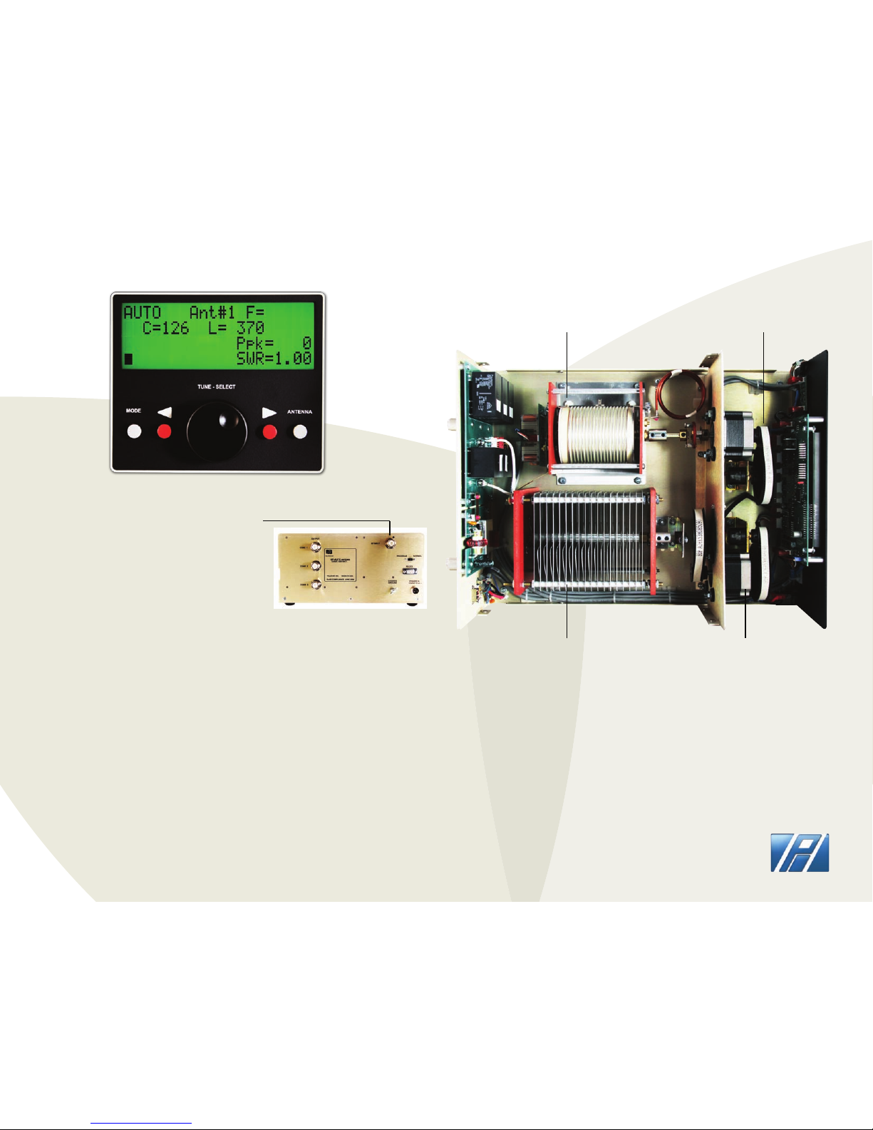
REPAIR OR REPLACEMENT MODULES
lAll PC Boards are removeable with standard American
tools in case of failure.
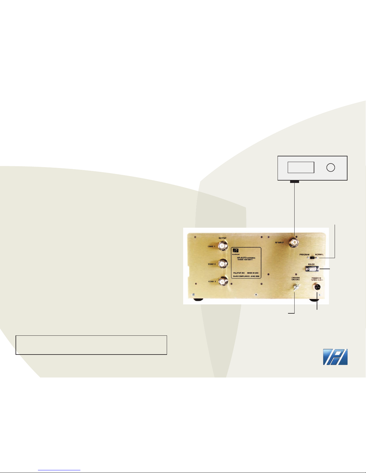
lThe rear panel (relay PCB) has custom S0-239
connectors that can be loosened witha 3/4“ socket and
4 x 6-32 keps nuts. Remove these nuts and two
connections from the variable and the entire relay PC
Board is removable without a soldering iron.
lBoth the front and rear panels can be lowered by
removing the 3 countersink screws from the bottom edge
of each panel.
MAINTENANCE REQUIREMENTS
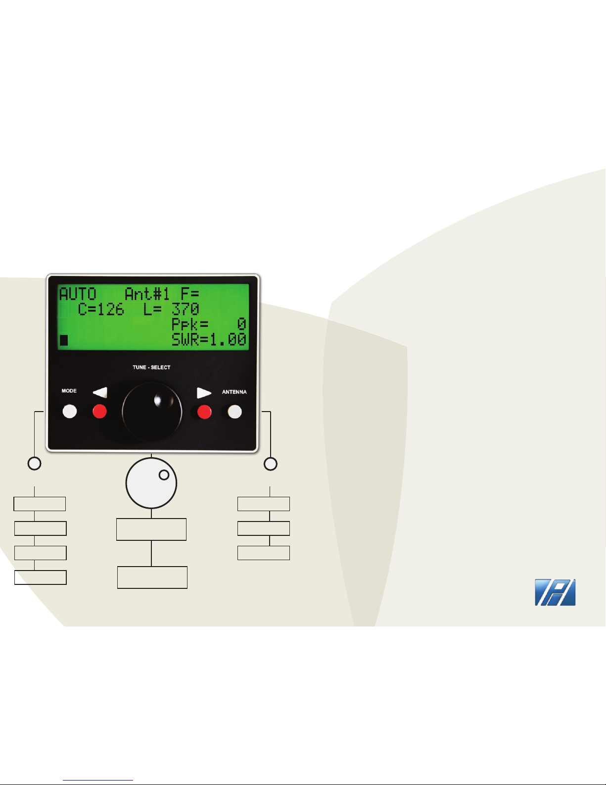
The HF-AUTO is a matching system that is a complete stand-alone RF
Tuneable Auto T Network tuner.
It is completely independent of data from an external source to
determine frequency of tracking from Band to Band. As a result of this
feature, the HF-AUTO will function with any transmitting device
without interconnecting data cable attachments.
The HF-AUTO uses an RF Coupler that provides voltage and current
information from 1.8 MHZ to 54 MHZ.
This informtion is then processed by a pair of processing devices that
provide accurate phase oriented forward and reected values that are
used in two TI processors to calculate SWR.
This allows for detection of frequency and SWR at very low levels,
typically 2 watts, and is scaled to read these levels up to 1800 watts.
The processors establish the threshold for tuning and uses this
information to see if a tuning sequence is required.
A preset voltage for all the frequencies are used to determine the
positions of the variable dierential capacitor and the roller inductor
by a precise mechanical sprocket and kevlar belt system.
This determines with great accuracy and repeatability the exact
location of L&C needed to execute a tune sequence. This system
samples DC voltage and compares this to the intended frequency band
and sees that if the SWR is more than the preset tuning set by the user
then the steppers for L & C will adjust to that voltage which will
represent the mimimum SWR.
This will be better than 1.2:1, typically 1.05.
Page 2
Page 13
THEORY OF OPERATION
PALSTAR

ON INITIAL POWER-UP
Display will indicate rev level of software and Palstar
copyright information.
SCREEN DISPLAY ON POWER-UP
Page 12
Page 3
HOW-TO UPDATE SOFTWARE
PRESS
TO SELECT
C AND L
TO SELECT
SETUP ITEM
DOWNLOADING HF-AUTO FIRMWARE
l CREATE a folder on your computer’s hard drive (but not desktop)
l NAME the folder HF_AUTOUPGRADE
l DOWNLOAD the Firmware le (Zip format) from the Palstar website -
http://www.palstar.com/en/hf-auto/ - it is near the bottom of the page .
The link to the le is named“HF-AUTO Firmware 1.x”
l SAVE the le to the folder you created in Step 1
l OPEN the folder by right-clicking on the Zip le and select “Extract All” -
follow the steps in the Extraction wizard
l TURN-OFF the HF-AUTO
l CONNECT the RS-232 cable to the rear panel
l CONNECT the other end of the RS-232 cable to Com 1 or your computer
l TURN-ON the HF-AUTO
l SET Switch at rear of the HF-AUTO to “PROGRAM”
l Note: LED (PROGRAM MODE) on Front Panel is illuminated
l DOUBLE-CLICK “LOAD_HF_9600”from your HF_AUTOUPGRADE folder that
you created in Step 2
l DOS Window appears - wait until DOS Window closes (approx. 1 min)
l TURN “PROGRAM” Switch to “NORMAL”
l REMOVE the RS-232 cable
l TURN HF-AUTO OFF and then ON again
l LOOK at HF-AUTO display to see new REV level at top-right corner when
you rst turn it on
l COMPLETE - you have now completed the update of the rmware
NOTE:
INSTALLING THE FIRMWARE UPGRADE
ANT #1
ANT #2
ANT #3
AUTO
MANUAL
BYPASS
SETUP
The HF-AUTO ships with a DB9 serial cable.
You can order a USB to DB9 serial cable
from Palstar for use with computers with no
DB9 serial port to update the rmware.
MODE TUNE KNOB
PRESS PRESS
ANTENNA
PALSTAR

Page 4
Page 11
SETUP MODE
HF-AUTO Firmware Summary
v1.18: - new default position settings made for the positioning of the C and L with
a given frequency range;
- added menu option to clear out the memory oset positions for the C and L
with a given frequency range;
- removed limits on the C and L oset position values;
- added menu selection of the Amp-Key relay state when no RF power is detected;
- added ability in manual mode to store a memory position using the Right Arrow
button;
v1.19: - changes regarding operation with the MARS frequencies.
v1.20: - allowed for the use of the new relay board with the proper jumper selection;
- added additional memory presets between 7.0 MHz and 14.0 MHz;
- manual mode now allowed the Left Arrow Button to return to Auto mode.
v1.21: - corrected problem where the display was not being updated after pressing left arrow
button and would make the unit go from Manual Mode to Auto Mode.
v1.22: - minor display corrections: UNABLE TO TUNE message remained on display in error after a
new tune operation started.
v1.23: - added Setup Menu item to select AUTO STORE to be ON or OFF;
- added Setup Menu item to select DELAY TUNE SWR to be ON or OFF;
- provided for using Ant 3 selection with dummy load by changing to AUTO ANT
SWITCH MODE state by pressing and holding of the ANTENNA button;
- added memory locations to have memory settings every 50 kHz from 28 MHz to 29.7 MHz.
v1.24: - removed Amp Key Relay Menu items;
- corrected problem where the display could be blanked out after the unit remained in the
Setup Menu for an extended time.
v1.25: - corrected an occassional problem in Auto Tune Mode if the unit has AUTO ANT SWITCH
set to ON;
- made improvements in the Auto Tune operation to reduce the time needed to nd the
C and L tune
- positions when a given frequency is rst applied.
v1.26: - corrected a problem where some units were incorrectly reading EEPROM calibration and
setting values.
v1.27: - removed restrictions in manual mode that prevent storing of new C and L positions when
those changes are only of a minimal number of steps. The restriction is there to prevent the
auto tune mode causing excessive writes to the EEPROM;
- corrected occassional problems in nding the absolute best match when v1.25 changes
were made;
- added to the operation when holding the ANTENNA button to select BYPASS MODE when
AUTO ANT SWITCH is turned OFF and select AUTO MODE when AUTO ANT SWITCH is turned ON.
v1.28 not released.
v1.29 - The selection of the antenna port in an auto frequency selection mode now is programmable
for each of the ten dierent HF bands;
- The INITIALIZE PRESETS menu option has been removed;
- The QUICK TUNE menu option has been removed;
- The last frequency of transmission is saved on power down and the inductor and antenna relay
settings are restored for that same frequency at power up in auto antenna mode;
- The power reading no longer has an option to be average power. Only peak power is displayed;
- The accuracy of the peak power has been improved;
- Added menu option to have last SWR reading remain on the display after power is removed;
- Added menu option to have last Power reading remain on the display after power is removed.
RANGE (WATTS):
TUNE LEVEL:
BACKLIGHT:
POWER UP MODE:
STEP SPEED:
AUTO ANT SW:
RETUNE DELAY:
POWER UP ANT:
AUTO STORE:
DELAY TUNE SWR:
LAST SWR DISP:
LAST POWER DISP:
100 | 250 | 1000 | 2500
1 – DIM | 2 - BRIGHT
AUTO | MANUAL | BYPASS
HIGH | MED | LOW
ON | OFF
ADJ 1-3 SECS
ANT 1 | 2 | 3
ON | OFF
ON | OFF
ON | OFF
ON | OFF
1.05 TO 1.64
FOR LICENSED USERS ONLY
MARS MIN-MAX
MARS FREQ ADJ
to SELECT MENU
PRESS
TUNE KNOB
PRESS
& ADJUST
with TUNE KNOB
to ADJUST VALUES
PRESS
RED BUTTONS
PALSTAR

Page 10
Page 5
TUNER OPERATION
1. CONNECT the transceiver to the RF INPUT
chassis connector at the rear of the back panel
2. CONNECT a dummy load to one of the coax
outputs or your desired antenna
3. APPLY a single tone level greater than 5 watts
(use FM MODE) typically 5 to 50 watts
4. DISPLAY will indicate Frequency, Power Level,
SWR, and Numerical value for C and L
NOTE: To execute a tune sequence at another band or frequency lower the
power of the transceiver or any other transmitting device to low power
and change frequency and the tuner will immediately follow to the
new location. You can also click the PTT button on your microphone in FM
MODE and accomplish the same at the lowest power level
TUNING THE HF-AUTO
Applying only a short burst of single tone power to the HF-AUTO will
allow the tuner to pretune to a memory segment containing the desired
frequency. ANOTHER application of RF Power must be applied to complete
the nal tune condition where high power may be applied. You can also
apply single tone power continuously until the nal tune cycle has compled
and get the same result. Trying to tune at high power without executing the
nal tune condition could damage the tuner.
PLACE TUNER IN AUTO MODE WITH GREY MODE BUTTON
INSIDE VIEW
ROLLER INDUCTOR
VARIABLE CAPACITOR STEPPER MOTOR
SUPPORT SUB-PANEL
PALSTAR will oer a fully remote version of the base version in the near
future. However, in certain cases where there is DC power available at
a reasonable distance you can operate this base version in the AUTO
MODE. Other functions would of course not be available.
The base version is frequency sensing you need only to insert a
metering device that could monitor reected power in the
transmitting location.
REMOTE OPERATION
PULLEY/BELT SYSTEM
PALSTAR

Page 6
Page 7
SAVING MEMORY LOCATIONS
l TUNE the HF-AUTO using a low power FM or CW signal
l MANUALLY tune L&C for best SWR while power applied
l While power is still applied push red button to the right of the tuning
knob and hold for 2 seconds or more until the display says
“SETTINGS CHANGED”
l Remove power and release the red button
l The frequency is now saved
l To return to AUTO MODE push left red button
DIVISIONS IN THE FREQUENCY BANDS FOR SETTINGS
FREQUENCY IN MHZ # OF SETTINGS SPACED
1.8 MHZ to 20 MHZ 51 4 Khz
3.5 MHZ to 4.0 MHZ 51 10 Khz
7.0 MHZ to 7.3 MHZ 36 50 Khz
10.1 MHZ to 10.150 MHZ 2 50 Khz
14.0 MHZ to 14.350 MHZ 18 40 Khz
18.068 MHZ to 18.168 MHZ 3 50 Khz
21.0 MHZ to 21.450 MHZ 5 100 Khz
24.890 MHZ to 24.990 MHZ 1 500 Khz
28.0 MHZ to 29.70 MHZ 51 500 Khz
50.0 MHZ to 54.0 MHZ 101 40 Khz
MARS FREQUENCY 707 4 Khz to 500 Khz
FOR ALL TUNABLE FREQUENCIES FROM 1.8 - 30 MHZ, 40 MHZ
THROUGH 41 MHZ AND 50 MHZ TO 54 MHZ THERE ARE 1193
SUBDIVISIONS OR MEMORY POSITIONS.
REAR PANEL OF HF-AUTO
ANTENNA OUTPUTS
OUTPUT
14.200
TRANSCEIVER
FIRMWARE UPDATE/
PROGRAM SWITCH
RS-232
DC INPUT
12 - 13.8 VDC
CHASSIS GROUND
WING-NUT
@ 4 AMPS
PALSTAR

INSIDE VIEW OF HF-AUTO
COPYRIGHT PALSTAR 2011-2014©
limit
limit
limit
stepper
Ant. #3
RF Path
PCB
J1
J2
J3
Ant. #1
J4 Pfwd/Prev
Freq. PCB
Ant. #2
Xmtr.
SC1
SC1
Differential
Tee
Network
SC2
SC3
SC2
SC3
Logic / Display/ Buttons
PCB
Interface
PCB
8pin
6pin
2 DC 10 pin
4pin
stepper
8pin8 pin
Stepper
Motors
4pin4 pin
P1
DC
J7
J6
J5
RS-232
On/Off
Switch
2 DC2 DC10 pin
8pin
6pin
P2
P2
P3
P3 P4
P4
P5
P5 P6
P7
P8
P9
P10
P11
SW1
Program/
Run
J1-J4 = SO-239
J5 = DE-9 Female
SW1 = SPST recessed switch (open = RUN)
J6-J7 = RCA Phono Female
P1 = DC male connector (>5A)
PCB connectors are .1" male 4-10 pins
All mating cable connectors are female
P5-P6 = AMP mate-N-lok
P9-P11 = 4 pin 0.1" spacing
P3 = 6 pin 0.1" spacing
P2, P7-P8 = 8 pin 0.1" spacing
P4 = 10 pin 0.1" spacing
Stepper motors now have different wiring
with no pins having 2 wires. 8 pin connector
is compatible with old 6 pin cables if connect
to pins 2-7.
HF-AUTO SCHEMATIC PALSTAR
Other manuals for HF-AUTO
1
This manual suits for next models
1
Table of contents
Other Palstar Tuner manuals

Palstar
Palstar AT User manual

Palstar
Palstar AT4K User manual

Palstar
Palstar AT2K User manual

Palstar
Palstar AT2KD User manual

Palstar
Palstar AT5K User manual

Palstar
Palstar AT1KM User manual

Palstar
Palstar BT1500A User manual

Palstar
Palstar AT-500 User manual

Palstar
Palstar BT1500A User manual

Palstar
Palstar AT1500DT User manual