manuals.online logo
Brands
  1. Home
  2. •
  3. Brands
  4. •
  5. Panametrics
  6. •
  7. Measuring Instrument
  8. •
  9. Panametrics PT878GC User manual

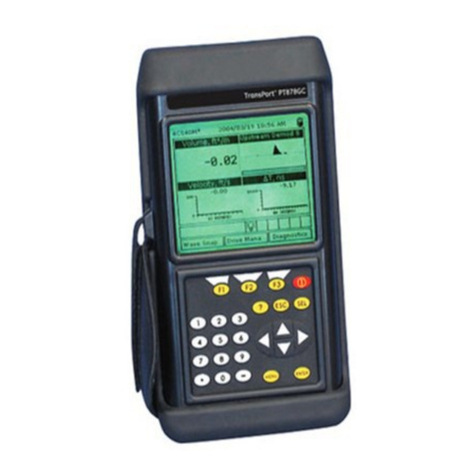
Panametrics PT878GC User manual

Useful Tips and Hints
Cable ends are protected by a metal sheath. To remove from the PT878 - pull the sheath back.•
The[ENTER]keyallowsyoutoenterandconrmaparameter,enteramenuandenteradropdownmenu.•
The red end of the cable needs to be placed on the upstream transducer and the blue end on the downstream transducer.•
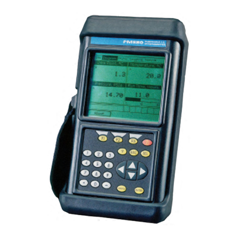
Keypad Description
The PT878 keypad has 25 function keys. The functions for each of the keys are as follows:•
3functionkeys([F1],[F2],[F3])-Enableyoutoselectthespecialfunctionswhichappearatthebottomofthescreen.•
12numerickeys(including[-]and[.])-Enableyoutoenternumericdata.•
4 arrow keys - Enable you to move through the menu options.•
[?] Help key - Enables you to acces online help•
[MENU] Menu key - Enables you to access the Main Menu•
[ENTER]-Enablesyoutoenteraparticularmenu,andentersselectedvaluesintothePT878memory.•
[SEL] - Enables you to move between data measurementson the screen.•
[ESC] - Enables you to exit menus or menu options at any time; cancels a numeric entry.•
RedKey-TurnsthepowerOnorOFF,andtogglesthebacklightOnorOff.•
Programming Transducer, Pipe and Fluid Parameters
Entering the Standard Volume / Mass Flow Parameters
The Standard Volume/Mass Flow option enables the user to correct standard volumetric
unitsfortemperatureandpressure.Italsoallowsyoutoenableordisablemassow.
3.TherstparameterallowsyoutoenableordisabletheStandardVolumeoption.
4. Use the arrow keys to scroll to correct radio button.
5.Press[ENTER]toconrmyourselection.
Note: If you select “Disabled” you cannot select any other prompts in this window.
1. Scroll to the Program Menu and press [ENTER].
6. The next option asks you to enter the base pressure. Press [ENTER] to open the text box
andusethenumerickeystotypethis.Press[ENTER]toconrmtheentry.
7. The next option asks for the atmospheric pressure. Press [ENTER] to open the text box
andusethenumerickeystotypethis.Press[ENTER]toconrmtheselection.
8.Thenalpromptinthiswindowasksforthebasetemperature.Press[ENTER]toopen
thetextboxandusethenumerickeystotypethis.Press[ENTER]toconrmtheselection.
PresstheuparrowkeytoreturntotheStandardVolumeprompt,andthenbacktotheSettingstab.
Toconrmtheentriesandreturntooperatemode,press[F3](OK).
Entering Inputs in the Standard Volume Option
2. Scroll across to the Inputs tab and press [ENTER] to open the Inputs window.
3.Scrolldowntotherstpromptwhichasksifthepressureisxedoractive.Scrolltothe
appropriateoptionandpress[ENTER]toconrmtheselection.
Note: Only select Active if you have live pressure and temperature readings being fed into
the meter.
4.Ifyouhaveselectedaxedpressure,youwillbeaskedtoenterthebasepressure.Press[ENTER]toopenthetext
boxandthenumerickeystoenterthepressurevalue.Press[ENTER]toconrmtheentry.
5.Thenextpromptwillappearwhetheryouhaveselectedanactiveorxedpressurevalue.
The desired input needs to be entered. Scroll from the Pressure text box to the Input menu
and press [ENTER] to open the drop down menu. Scroll to input A or B and press [ENTER]
toconrmtheselection.
6.Thenextpromptasksifthetemperatureisxedoractive.Scrolltothecorrectoptionand
press[ENTER]toconrmtheselection.
7.Ifyouhaveselected axedtemperature,youwill beaskedtoenter thetemperature
value. Press [ENTER] to open the text box and use the numeric keys to enter the temperature
value.Press[ENTER]toconrmtheentry.
8.The nextpromt willappear whetheryou have selectedan activeor xedtemperature
value. The desired input needs to be entered. Scroll from the Temperature text box to the
Input menu and press [ENTER] to open the drop down menu. Scroll to input A or B and press
[ENTER]toconrmtheselection.
Note: Ifyouhaveswitchedbothactiveinputsto#A(orto#B),thePT878GCautomaticallyswitchesoneinputtothe
other letter. This change ensures that only one analog input is assigned to one measurement type.
Entering Mass Flow Parameters
1.ToentermassowparametersintheStandardVolume/MassFlowoption,scrollacross
to the Mass Flow tab and press [ENTER] to open the window.
2.TherstpromptasksifyouwanttoenableordisabletheMassFlowoption.Scrolltothe
appropriateoptionandpress[ENTER]toconrmtheselection.
3. If you have selected “Enable” Mass Flow the following prompt will appear asking for the
calculatedmethod.Threeoptionsareavailable:staticdensity,saturatedsteamandsteam.
Press [ENTER] to open the drop-down menu. Scroll to the appropriate method for your
applicationandpress[ENTER]toconrmtheentry.
- If you select Saturated Steam: The prompt asks for the Saturated Steam input. Press
[ENTER]toopenthetextbox,entertheappropriatevalue,andpress[ENTER]toconrm
the entry.
- If you select Static Density: The prompt asks for the Static Density value. Press [ENTER] to
openthetextbox,entertheappropriatevalue,andpress[ENTER]toconrmtheentry.
1.Toenterstandardvolumeinputs,returntothesettingstabatthetopoftheStandard
Volume window.
Note: Ifyouselect“Disabled”,youcannotselectanyotherpromptinthiswindow.
2. Scroll down to the Std Vol / Mass Flow button and press [ENTER].
BeforethePT878canbegintakingmeasurementstheuserneedstoenterthetransducer,
pipeanduidparametersbyfollowingthesesteps:
1. Press the [MENU] key and scroll across to the Program Menu tab using the arrow keys.
Press[ENTER]to enterthemenu,and then[ENTER]again toenterthe TransducerMenu
(seepiconright).
2. Work through the transducer options selecting the appropriate options from the drop
downmenus,ormanuallytypein the correctselection(ifaboxis greyed outyoudonot
need to enter a selection for this parameter). Wedge temperature is typically half way
between the pipe and air temperatures.
3.Once you havecompleted the transducertab, scroll to the topof the page andpress
the right arrow to highlight the Pipe Menu tab. Press [ENTER] to open the Pipe Menu. Work
through the options as in step 2.
6. The meter should display the following warning message: “WARNING: TRANSDUCER
SPACINGHASCHANGED”.Thisisthespacebywhichyouwillneedtosetthetransducers
apart by.
4.Repeatstep3onthethreeremainingtabs,Fluid,LiningandPath.
5.Oncecompletepress[F3]toconrmyourchoicesandreturntothemainscreen.
Error Messages and Testing the Cables and Transducers
AwayoftestingthatthecablesandtransducersareworkingistoconnectthemalluptothePT878GCandputthetransducertoyourear.Listen
out for a frequent buzzing sound. If you do not hear this there is a problem with either the cables or transducers.
Make sure the transducers are spaced properly.
Error messages - error code messages are displayed when the PT878 is displaying measurements. For meanings of error messages and a full list
ofsolutions,pleaserefertotheDiagnosisandTroubleshootingsectionoftheGEPanametricsOperationandInstallationGuide.
E0-Errormessageisdisplayedbrieyafteranothererrormessage.Noactionisneededinthiscase.
E1-Themeterhasapoorultrasonicsignalstrength.Thiscouldbedowntobrokencables,brokentransducers,owcell  
problems or electronic failure.
E2 - Soundspeed error. This could be caused by incorrect programming and spacing of the transducers.
E3-Velocityrangeerror.Causedbyincorrectprogramming,incorrectspacingoftransducersorpoorowconditions.
E4-Signalqualityproblem.Iftoolowitisaowcellorelectricalproblem.Iftoohighitiselectronicfailure.Possiblychangetocorrelatemode
under signal setup
E5-Amplitudeerror.Thereareexcessivebubblesorparticlesintheuid.
PressingtheupkeyreturnsthemetertotheMassFlowprompt,andthentotheMassFlow
tab.
ToconrmtheentriesandreturntoOperatemode,press[F3](OK).
Panametrics PT878GC Ultrasonic Flowmeter
Quick Start Guide

www.rshydro.co.uk [email protected]
Setting Up A New Log Transferring Log Files to PC
Saving Site Data
Installing the Clamping Fixtures and Transducers
1.OncealloftheparametershavebeenenteredandconrmedthePT878GCwillgiveyoutheopportunitytosavethe
settingtoasitele.
2. To save the data to the site open the Site Menu by pressing [MENU] and [ENTER].
3. Use the arrow keys to scroll down to the save now option and press [ENTER].
4.Awindowwillappear.Press[F2]tocancelsavingthesiteor[F3]toconrmsavingthesite.
Note: To save the parameters under another site name, refer to chapter 4 in the user manual.
1.Tocreateanewlogyourstneedtoentertheloggingmenu.Todothispressthe[MENU]buttonandscrollacross
toLoggingMenu.Press[ENTER],scrolldowntonewlogandpress[ENTER]again.
3.ThePT878GCwillaskforlogformattingandmeasurements.
2. The create new log screen appears. Use the arrow keys and enter to create the log name.
[F1]todeleteacharacterand[F3]toconrmtheentry.
5.NextyouneedtochoosebetweenastandardorerrorlogandconrmwithEnter.
4. You will be asked to choose between a linear or circular format for the log. Select using
the arrow keys then press enter.
6. The next prompt asks for the starting time and date. You can use the numeric keys or the
arrowkeystochangea highlighted numbertothedesired one.Press[ENTER]toconrm
theentry.(Theowmeterwillautomaticallydefaulttoa1hourlogat60secondintervals)
7. Follow the same procedure to enter the end date and time.
8.Thenalpromptasksyoutoenterthelogginginterval.Usethenumerickeystoenterthe
desiredintervalinsecondsandthenpress[ENTER]toconrmtheentry.
11. Scroll to the desired output category and press [SELECT] to move to the list of units.
Choosetheappropriateunitandpress[F3]toconrmyourselection.
9.Younowneedtosetthemeasurementstoberecorded.ScrolluptotheGeneraltaband
across to the ‘Measurements’ tab. Press [ENTER] to go to this tab.
10.Press[ENTER]ontherstmeasurementtoopentheMeasurementstab.
12. Repeat this with up to 12 parameters.
13.Whenyouhavenished,press[F3](Activate)toconrmtheentriesandstartthelog.
Note: Select a linear log if you would like the meter to stop logging once the memory is full
or select a circular log if you wish to overwrite old data readings once the memory is full.
1. Check that the communications option has been set to the IrDA protocol.
2. Check that there is a clear path between the IR port on the PT878 and the IR sensor
connected to the PC. If clear the PT878 and PC will automatically connect.
3. Press the [MENU] button and scroll across to the Logging tab and press [ENTER].
4. Press [ENTER] again to enter the Log Manager.
5. Use the arrow keys to highlight the log you wish to
transfer in the left hand panel.
6. Press [MENU] to jump to the File tab and press [ENTER].
7. Scroll to Transfer and press [ENTER]. The PT878 will search for IR devices.
8.WhenthePT878GCndsanIRdevice,amessagewillappeartoindicatethattheleis
being uploaded. The computer will ask if you want to accept the data.
9.ThelecanthenbeopenedonthePCusingthePanaLogViewerandcanthenbeexported
to Microsoft Export format.
Pleasenotethatacompleteinstallationinvolvestheclampingxtures,transducersanddampeningmaterial.Ifyouare
using dampening material please refer to the installing dampening material section.
1.Theclampingxtureisinstalledintwohalves.Thersthalfofthextureisinstalledwiththefourrods,needstobe
positioned on the horizontal plane on the pipe at the 3 o’clock position.
Installing the Clamping Fixture
3.Thefournutsshouldnowbeinstalledontotherodswiththeconvexsideofthenutfacingthexture.Hand
tighten the nuts.
2.Thesecondhalfofthextureshouldbepositionedoverthethreadedrodsinthe9o’clockposition.
2.Therstmountingblockshouldbesetataconvenientnumber
onthescalesuchas1inor1cm.Installthersttransducerinthe
mounting block with the BNC connector pointing away from the
center of the V block xure. Tighten the thumbscrew onto the
slider until the transducer is tight against the pipe surface.
1. Apply a thin line of couplant along the entire length of each
transducer face.
3. Set the second mounting block to the calculated spacing plus
theinitialscalenumberselectedfortherstmountingblock.
4. Install the second transducer in the same way.
Note: Eachhalfofthexturehasameasuringscale.Ensurethatthescalesareonthesamesideofthexture
with zero at the same origin.
Installing the Transducers
Installing the Dampening Material
1.Oncetheclampshavebeeninstalled,useamarkerpentomarktheinsideedgesofthebracketsonthepipe.
2.Removetheclampingxturesandtransducersfromthepipe.
3. Thoroughly dry the pipe using a towel or rag.
4.Cutanequallengthtothecircumference,ofdampeningmaterialandpeeloffthepaperbacker.
5. Wrap around the pipe following the lines already marked on the pipe which represent the inside edge of the clamping
xture.
6.Theclampingxturenowneedstobereinstalledandthetransducers
mounted ensuring the spacing is set correctly.
7.Usingamarkerpen,drawaroundthetransduceroutline.
8.Onceagainremovethetransducersandclampingxture.Useaknife
to cut out the transducer shape and peel the dampening material from
the pipe.
9. Clean the cut out area of the pipe to remove any excess residue.
10.Reinstalltheclampingxtureandtransducers.
11.Cutanotherlengthofdampeningmaterial,equaltothecircumference.
Cutthisintotwopieces,each4.5inwide.
12.Wraponestriponeachsideoftheclampingxture.
Changing the Displayed Parameters
To change the amount of measured parameters / views on the main screen. First press
[MENU] and scroll down the Site menu to the required view. Once it is highlighted press
[ENTER].Themainscreenwillnowchangetothechosenamountofviews.Fornextstage,
hide menu by pressing [MENU].
1. Use the arrow keys to scroll to the parameter view you wish to change. Press [ENTER]
when you have this highlighted.
Changing the Measured Parameters
3. Scroll to the measurement you want to be displayed and press [SELECT]. The cursor will
jump across to the unit list.
2. Scroll across to the Measurement tab and press [ENTER].
5.Conrmyourchosenselectionbypressing[F3](OK).
4. Scroll to the required unit and press [SELECT].
6. The PT878 will now return to the main screen and will display the new chosen
parameter.
This guide has been created as a result of customer feedback. Another example of RS Hydro’s customer support.
Other manuals for PT878GC

1

Other Panametrics Measuring Instrument manuals

Panametrics PanaFlow XMT1000 User manual

Panametrics

Panametrics PanaFlow XMT1000 User manual

Panametrics MG2 User manual

Panametrics

Panametrics MG2 User manual

Panametrics HydroProII User manual

Panametrics

Panametrics HydroProII User manual

Panametrics DigitalFlow XMT868i User manual

Panametrics

Panametrics DigitalFlow XMT868i User manual

Panametrics CTF878 User manual

Panametrics

Panametrics CTF878 User manual

Panametrics DewPro MMY30 User manual

Panametrics

Panametrics DewPro MMY30 User manual

Panametrics PanaFlow MV80 User manual

Panametrics

Panametrics PanaFlow MV80 User manual

Panametrics Sentinel User manual

Panametrics

Panametrics Sentinel User manual

Panametrics XDP-H2 User manual

Panametrics

Panametrics XDP-H2 User manual

Panametrics PT878GC User manual

Panametrics

Panametrics PT878GC User manual

Panametrics DigitalFlow GC868 User guide

Panametrics

Panametrics DigitalFlow GC868 User guide

Panametrics CGA 351 User manual

Panametrics

Panametrics CGA 351 User manual

Panametrics flare.IQ Generation 2 User manual

Panametrics

Panametrics flare.IQ Generation 2 User manual

Panametrics DigitalFlow DF868 Owner's manual

Panametrics

Panametrics DigitalFlow DF868 Owner's manual

Panametrics DigitalFlow GS868 Owner's manual

Panametrics

Panametrics DigitalFlow GS868 Owner's manual

Panametrics GF868 Owner's manual

Panametrics

Panametrics GF868 Owner's manual

Panametrics GF868 Owner's manual

Panametrics

Panametrics GF868 Owner's manual

Panametrics Aurora H2O User manual

Panametrics

Panametrics Aurora H2O User manual

Panametrics DigitalFlow GC868 User manual

Panametrics

Panametrics DigitalFlow GC868 User manual

Panametrics DigitalFlow GC868 Owner's manual

Panametrics

Panametrics DigitalFlow GC868 Owner's manual

Panametrics PanaFlow LZ User manual

Panametrics

Panametrics PanaFlow LZ User manual

Panametrics GF868 User manual

Panametrics

Panametrics GF868 User manual

Panametrics CTF878 User guide

Panametrics

Panametrics CTF878 User guide

Panametrics DewPro MMR31 User manual

Panametrics

Panametrics DewPro MMR31 User manual

Popular Measuring Instrument manuals by other brands

Endress+Hauser Teqwave F operating instructions

Endress+Hauser

Endress+Hauser Teqwave F operating instructions

Tuthill FILL-RITE TT10A Operation and safety manual

Tuthill

Tuthill FILL-RITE TT10A Operation and safety manual

BASI BFM921 user manual

BASI

BASI BFM921 user manual

Sea-Bird Scientific SBE 39plus-IM user manual

Sea-Bird Scientific

Sea-Bird Scientific SBE 39plus-IM user manual

Apogee MO-200 Series quick guide

Apogee

Apogee MO-200 Series quick guide

3M ESD Pro user guide

3M

3M ESD Pro user guide

Electronic Educational Devices Watts up Operator's manual

Electronic Educational Devices

Electronic Educational Devices Watts up Operator's manual

RC Electronics Eagle manual

RC Electronics

RC Electronics Eagle manual

Keysight M9703A Series Startup guide

Keysight

Keysight M9703A Series Startup guide

Temperature Guard M309 instructions

Temperature Guard

Temperature Guard M309 instructions

multicomp pro MP780647 instruction manual

multicomp pro

multicomp pro MP780647 instruction manual

Solinst 101 Replacement manual

Solinst

Solinst 101 Replacement manual

Vetus AMPMETER manual

Vetus

Vetus AMPMETER manual

Endress+Hauser Ceraphant PTP31B operating instructions

Endress+Hauser

Endress+Hauser Ceraphant PTP31B operating instructions

Curtis 906 instructions

Curtis

Curtis 906 instructions

Siemens SICAM P27 manual

Siemens

Siemens SICAM P27 manual

Full Gauge Controls EnergyLOG plus manual

Full Gauge Controls

Full Gauge Controls EnergyLOG plus manual

Secabo Modular Crosslaser System instruction manual

Secabo

Secabo Modular Crosslaser System instruction manual

manuals.online logo
manuals.online logoBrands
  • About & Mission
  • Contact us
  • Privacy Policy
  • Terms and Conditions

Copyright 2025 Manuals.Online. All Rights Reserved.