5COAXIAL RETROREFLECTIVE TYPE LS-H901□
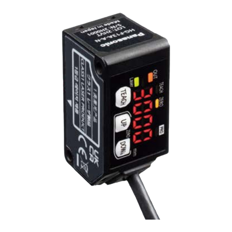
● In principle, the coaxial retroreective type (LS-H901□) may be unable to detect a
mirror object or an object which easily diffuses the receiving light at a short sens-
ing distance since the polarized light becomes unstable.
In this case, take the following measures.
<Measures>
• Lower the receiving light sensitivity with the light-receiving sensitivity function of
the amplier.
• Change the response time.
• Make the distance between the sensor head and the sensing object farther.
●The receiving light sensitivity may change depending on the surface condition of
the reector. When a threshold value is set with the applicable amplier LS-500
series, sufcient margin should be taken into account.
6WIRE CONNECTION
●The cable of sensor head can be shortened to your desired length. However, it
cannot be extended.
<Connector for amplier connection>
Wire inlet
Wire inlet
Operating lever (white)
Strip gauge Release lever
Operating lever
(white)
Releasing slot
Wire connecting procedure
1. Process the core length to 7 to 8mm in ac-
cordance with “STRIP GAUGE” indicated on
the side of this unit, and twist the core sev-
eral times.
When using shielded wires, twist the wire un-
til obtaining the diameter of ø1.2mm or less.
Wire
Core length
7 to 8mm
2. Use a flathead screwdriver (Blade width:
2 mm or less) to push the operating lever
(white) located at the operating area until it is
locked.
Blade width
2mm or less
Flathead
screwdriver Operating lever
(white)
2. Push
3. Insert the wire to the innermost of the wire
inlet. Check that the shielded wire is properly
inserted into the wire inlet as well as that the
core end has passed through the wire con-
nection area as shown in the right gure.
Wire connection area
Core end
Shielded wire
Wire
inlet
3. Insert
1
3
5
2
4
6
Terminal No. Connecting cable
1 Purple
Thru-beam type · Emitter: Gray
Coaxial retroreective type, Diffuse reective type: Black (with gray stripe)
2 White
3 Shield
4 Shield
Thru-beam type · Receiver: Black
Coaxial retroreective type, Diffuse reective type: Black
5 Black
6 Pink
4. Place the head of a athead screw-driver un-
derneath the operating lever (white) through
the releasing slot, and lift the screwdriver
head. If you hear a snap, the operating lever
(white) is returned and the wire is xed.
Operating lever
(white)
Releasing slot
4. Lift
5. Lightly pull the wire to ensure that wire is not
loose.
Releasing procedure
1. Use a flat-head screwdriver (Blade width:
2mm or less) to push the operating lever
(white) located at the wire inlet and remove
the wire.
Flathead
screwdriver
Operating lever
(white)
1. Remove
7SPECIFICATIONS
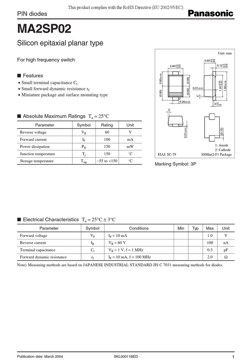
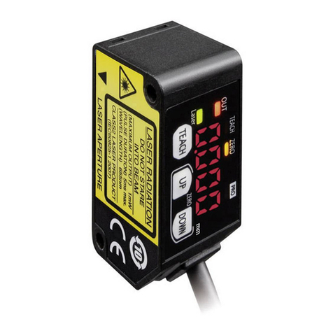
Type Thru-beam type Coaxial retroreec-
tive type (Note 1)
Diffuse reective
type
Cylindrical Small
Model No. (Note 2) LS-H101 LS-H102 LS-H901 LS-H201
Applicable amplier LS-500 series
Sensing
range
(Note 3)
STD mode
0 to 1m 0 to 1m
0.01 to 1m 0 to 300mm
LONG mode 0.01 to 1.5m 0 to 450mm
U-LG mode 0.01 to 2m 0 to 600mm
HYPR mode 0.01 to 2.5m 0 to 750mm
H-SP mode 0.01 to 1m 0 to 150mm
FAST mode 0.01 to 1m 0 to 200mm
Ambient temperature -10 to +55°C (No dew condensation or icing allowed), Storage: -20 to +70°C
Ambient humidity 35 to 85% RH, Storage: 35 to 85% RH
Emitting element Red semiconductor laser Class 1 (IEC / JIS / GB standard)
(Max. output: 2mW or less, Peak emission wavelength: 660nm)
Material
Enclosure: Stainless steel
Front cover:
Polycarbonate
Enclosure:
Polybutylene terephthalate
Front cover: Acylic
Enclosure: Polybutylene terephthalate
Front cover: Glass
Cable 0.11mm2(shielded wire: 0.16mm2) shielded cable, 2m long
Weight Each emitter and receiver: Approx. 50g Approx. 50g
Accessories
M6 nut: 4 pcs.
Toothed lock washer
: 2 pcs.
MS-EXL2-2
(Metal plate): 2 pcs.
RF-330 (Reector):
1 pc.
MS-LS-1
(Metal plate): 1 pc.
MS-LS-1
(Metal plate): 1 pc.
Notes: 1) The model No. of retroreective type sensor with the sufx “-Y” is the sensor without the RF-330 reector.
Arrange the reector separately.
(e.g.)
LS-H901-Y
2) The model No. with sufx “-C5” stands for the 5m cable length type.
(e.g.)
LS-H101-C5
3) Congure the mode settings in the applicable amplier LS-500 series.
8CAUTIONS
This product has been designed to meet the specications when it is used along
with the optional exclusive amplier. If an amplier other than the exclusive ampli-
er is used, not only the specications may not be met, but it may also be a cause
for malfunction or break down. Hence, please ensure to use this product along with
the optional exclusive amplier.
●This product has been developed / produced for industrial use only.
● Always use the sensor with the connector to be joined to the amplier.
● Make sure that the power is off while wiring to the amplier.
●In case noise generating equipment (switching regulator, inverter motor etc.) is
used in the vicinity of this product, connect the frame ground (F.G.) terminal of the
equipment to an actual ground.
●If power is supplied from a commercial switching regulator, ensure that the frame
ground (F.G.) terminal of the power supply is connected to an actual ground.
●Do not use the sensor during the initial transient time (0.5 sec.) just after the
power supply is switched on.
●Do not use the sensor during the initial transient time (0.5 sec.) just after the
power supply is switched on.
●Do not run the wires together with high-voltage lines or power lines or put them in
the same raceway. This can cause malfunction due to induction.
●When using the thru-beam type LS-H101 or LS-H102, do not set the receiving
light sensitivity (gctL) of the applicable LS-500 series amplier to level 2 or less.
This is because there is a possibility of sensing becoming unstable.
● Take care that the sensor head is not directly exposed to uorescent lamp from a
rapid-starter lamp or a high frequency lighting device, as it may affect the sensing
performance.
● The sensor head cable cannot be extended.
●Make sure that stress is not applied to the sensor head cable joint.
●This sensor is suitable for indoor use only.
● Do not allow any water, oil ngerprints, etc., which may refract light, or dust, dirt,
etc., which may block light, to stick to the emitting/receiving surfaces of the sensor
head. In case they are present, wipe them with a clean, soft cloth or lens paper.
●Do not use the sensor in vaporous, dusty or corrosive gas atmospheres.
●Take care that the sensor does not come in contact with water, oil, grease or or-
ganic solvents, such as, thinner, etc.
●Make sure that the power is off while cleaning the emitting / receiving windows of
the sensor head.
●When carrying out teaching using the applicable LS-500 series amplifier, set
a threshold which provides a reasonable margin. If there is insufcient margin,
sensing will become unstable.
●This device is using a laser which has high directional quality. Therefore the beam
possibly be out of alignment by the mounting condition of this device or distortion
of housing etc. Make sure to adjust the beam axe alignment before use.
●Since vibration, impact and ambient temperature affect the sensitivity, the installa-
tion and the sensitivity adjustment must have some margins.
http://panasonic.net/id/pidsx/global
Overseas Sales Division (Head Ofce)
2431-1 Ushiyama-cho, Kasugai-shi, Aichi, 486-0901, Japan
Phone: +81-568-33-7861 FAX: +81-568-33-8591
For sales network, please visit our website.
PRINTED IN JAPAN © Panasonic Industrial Devices SUNX Co., Ltd. 2017
